ANLEITUNG ZUM GEBRAUCH - INSTRUCTION BOOKLET GASHERDE GAS COOKERS JGS 1000 JGS 1010 JGS 3010 JGS 5010 JGS 5110 2 DE
ENGLISH DISPOSAL OF PACKING HINTS ON THE DISPOSAL OF PACKING In case of not making use thereof we recommend to put: Except for wooden material, packing and auxiliary material of Juno Major Appliances are recyclable and on principle should be handed over to recycling stations. - paper, cardboard and corrugated board as well as - plastic packing material and - metal packing material - After delivery to your premises packing of major appliances may be returned to our contract forwarders.
TABLE OF CONTENTS Description of the appliance Page 36 Hints on the use Page 42 Control panel Page 37 Chart with cooking times Page 45 Technical data Page 38 Cleaning and care Page 46 Instructions for use Page 39 Installation instructions Page 48 Open burners Page 39 Connection to the mains Page 50 Oven Page 40 Conversion to other type of gas Page 51 Use of the electric grill Page 42 What to do, if ...
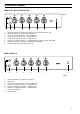
CONTROL PANEL MOD. JGS 1000-1010-3010-5010 Fig. 3 2 10 1 6 7 8 4 5 9 1. 2. 3. 4. 5. 6. 7. 8.
TECHNICAL DATA MODELL JGS 1000 Sizes: H = mm W = mm D = mm with top lid closed H = mm with top lid opened H = mm height adjustable by mm JGS 1010 JGS 3010 850 500 600 870 1430 15 Output of gas burners Heavy-duty burner Standard burner Cooking burner Oven burner 850 500 600 870 1430 15 850 600 600 870 1430 15 3000 2000 1000 3000 1.
INSTRUCTIONS FOR USE OPEN BURNERS ● The open burners are thermoelectrically secured in a way that the feed of gas will automatically be shut off when the flame goes out. ● Lay the burner caps always exactly on the burner chalice. ● The slots of the burner chalice must not be obstructed. ● The burner caps are enamelled ● Operate the open burners with items to be cooked put on, only! Fig.
COOKING ON THE OPEN BURNERS PRESERVATION When switching on the open burners for first-boiling/ frying, start at first with a big flame, and afterwards set back to a small flame for cooking on. The pot size must be chosen in a way that the flames will not exceed the pot rim. You may use pots of at least 240 to 260 mm diameter with the heavy-duty burner, pots of at least 200 to 220 mm diameter with a standard burner, and pots of about 160 mm diameter and smaller with the auxiliary burner.
PUTTING INTO OPERATION OF THE OVEN BURNER ● Attention! When operating the oven burner the ceiling slide must be pushed in against stop. ● The oven burner is ignited with the door opened. 2 10 1 ● Turn the oven control knob to the left in porition 10, push in against stop, and ignite the gas flowing out. After ignition keep the control knob pushed in for about 5 more seconds until the temperature sensor is sufficiently heated and the flame remains stable.
USE OF THE ELECTRIC GRILL Attention: ● When using the electric grill the accessible parts can be hot. Keep children off the appliance. ● The electric grill is used with half opened door. The protective screen must also be installed. To switch on the electric grill push in the oven control knob and turn clockwise to marking . When grilling direct on the wire shelf (grilling food), push the fat collector into the rails under the grill. Fig.
PREHEATING If need be, preheat the oven acc. to the instructions in the baking/roasting chart. BAKING IN THE OVEN Cakes on the baking sheet or in the drip pan are baked on the middle shelf level, only. With that always insert only one baking sheet. Put cakes in a baking tin always on the wire shelf. With that the baking tin should not protrude over the rear rim of the wire shelf. Several baking tins can also be put on the wire shelf.
POULTRY Poultry is of high value for nutrition and taste. Preparation is possible in a fresh or defrosted state. Carefully clean the poultry, have it drip off and swob dry. Then salt inside and season. Poultry can also be stuffed just as you like. Poultry can be prepared in a big roasting vessel, on the wire shelf, or direct in the drip pan. Have fat roasts cook on the wire shelf in order to enable the fat to drip off. At first pour about ˚ l of hot water into the drip pan.
CHART ON BAKING / ROASTING / GRILLING Dishes Weight (g) BAKING Pastries in moulds High ring cake Marble cake Cake in oblong tin Cheese cake Sponge cake Tart base, stirred dough Pastries on baking sheets Rye bread Yeast plaited loaf ´Strudel´ Yeast cake with dry topping Yeast cake with wet topping Swiss roll Small pastries (stirred dough) Small pastries (puff paste) Rolls Cream buns / éclairs ROASTING Meat Roast pork Roastbeef Roast veal, abt.
CLEANING AND CARE - For cleaning do not make use of scouring agents, caustic cleaners and hard objects. - Do not scratch off burnt-in residues, instead soak them with a wet cloth or with hot water resp. and remove with a little cleanser additives. OPEN BURNERS For the cleaning of pot rests, hob unit and open burner sections use hot water with a little cleanser additive; also clean the temperature sensor with a small soft brush. The slots of the burner chalice must be kept clean, too.
TOP LID REMOVAL AND REINSERTION For better cleaning the top lid can be removed. - For removal fold up the lid and remove upward. For reinsertion of the lid introduce the pivot pins vertically into the pin guide. OVEN LAMP Fig. 13 FO 0418 Prior to replacement the cooker must be separated from the mains by unscrewing the fuses or switching off the circuit-breaker! Unscrew the glass cover in anticlockwise direction and replace the bulb (socket E 14, 230V, 25 W, 300°C).
MONTAGEANWEISUNG IMPORTANT HINTS ● The connection of the gas cooker must exclusively be carried out by an approved gas fitter.
GAS COOKER INSTALLATION When installing the gas cooker a safety distance of 15 mm must be kept towards the adjacent furniture. If this safety distance cannot be kept, a thermal insulation will have to be located between the side panels and the furniture. Align the gas cooker horizontally. For that do horizontally align the open burners by means of the set screws mounted in the base and adapt the upper edge of cooker to the adjacent furniture.
CONNECTION TO THE MAINS The appliance is designed for the operation with a onephase supply voltage of 230 V. The electrical connection must be carried out acc. to the valid standards and the relevant legal prescriptions. Before the execution of the electrical connection make sure that - fuselage and house installation are designed for the max.
CONVERSION TO OTHER TYPE OF GAS When converting to a different type of gas there is need for an additional setting of the amount of gas or for a replacement of jets resp. (see charts I to VII). CONNECTION TO LPG A metallically sealed connection piece 8 x 1 mm must be fitted to the R 1/2“ gas supply socket. When doing so please focus on leakage testing . REPLACEMENT OF OPEN BURNER HIGH-BURNER JETS - Remove pot rest, burner cap and burner chalice. - By means of a wrench replace the high-burner jets acc.
REPLACEMENT OF OVEN JET - - Pull out the oven bottom sheet. Unscrew the fastening screw and remove the oven burner Turn out the burner jet and insert the jet suitable for the new type of gas acc. to charts I to VII. Re-install in reverse sequence. OVEN TEMPERATURE CONTROL oven burner Fig. 23 FO 1132 Instructions for the adjustment of the by-pass needle of the oven burner thermostat.
THERMAL LOAD, THROUGHPUT OF GAS, MARKING OF JETS Chart I Cooker setting Natural gas "E" 20 mbar H5 = 37,78 MJ/m3 W5 = 50,72 MJ/m3 Natural gas "LL" 20 mbar H5 = 32,49 MJ/m3 W5 = 41,52 MJ/m3 LPG 50 mbar H5 = 125,81 MJ/m3 W5 = 87,33 MJ/m3 Burner spot Auxiliary burner Standard burner Heavy-duty burner high low high low high low Thermal load kW 1 0,33 2 0,45 3 Throughput of gas l/h 95 31 190 43 Marking of jets 70 E 96 Thermal load kW 1 0,33 Throughput of gas l/h 111 Marking of jet
Chart III Conversion from natural gas E to ... Oven burners NATURAL GAS LL LPG High-burner Unscrew high-burner jet (fig. 23, 24, 25) and screw down the jet for gas LL acc. to chart I. Low-burner No conversion Primary air Unscrew high-burner jet (fig. 23, 24, 25) and screw down the jet for LPG acc. to chart I. Unscrew low-burner jet (fig. 26) and acc. to chart I screw down the setting jet for LPG until stop. No conversion Conversion from LPG to ...
Chart VI Conversion from natural gas LL to ... Open burners NATURAL GAS E LPG High-burner Low-burner Unscrew high-burner jet (fig. 20) and screw down the jet for natural gas E acc. to chart I. No conversion Unscrew high-burner jet (fig. 20) and screw down the jet for LPG acc. to chart I. Unscrew low-burner jet (fig. 22) and acc. to chart I screw down the setting jet for LPG until stop.
WHAT TO DO, IF ... To file an after-sales-service call is not always necessary. In some cases you may cure the problem by yourself. For this purpose please find some hints below. Important! Repair work must exclusively be carried out by experts. Inappropriate repairs may result in considerable danger for the user. What is, ... Possible cause Remedy ... if a liquid or a highly liquid dough is distribuited rather unilaterally? Appliance not horizontally installed.
SERVICE AND SPAREPARTS The gas cocks must be periodically lubricated to ensure good working and safety. Maintenance should be performed as follows: ● Remove the knob and panel after having taken out fastening screws. ● Loosen the two screws located at the sides of the cock bar. ● Remove the cone and clean it carefully. ● Then, apply a thin layer of grease non soluble in water, suitable for gas cocks. Take care not to obstruct the gas flow holes by an excess of grease.