
Installation Guide

1. Read all instructions.
2. Do not install this trac in damp or wet locations.
3. Do not install any part of Trac System less than 5’ above floor.
4. Do not install any fixture assembly closer than 6 inches from any curtain or similar combustible material.
5. Disconnect electrical power before adding to or changing the configuration of the trac.
6. Do not attempt to energize anything other than lighting fixtures on the trac. To reduce the risk of fire or electrical shock
do not attempt to connect power tools, extension cords, convenience receptacle adapters, appliances or the like to the trac.
7. Trac is not intended to be connected with power cord or to more than one branch circuit. If improperly wired, the trac system
may appear to operate acceptably, but an electric shock hazard may result. Check with a qualified electrician before wiring trac.
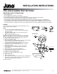
R21 End Feed
Polarity
All trac components are mechanically and visually polarized to assure
proper connections and grounding.
NOTE:
1. Trac face has polarity line indicating positive side.
2. Trac connectors have arrow which must point towards polarity
line on trac section.
3. Trac fixture adapter has arrows which must point toward the
polarity line on trac system.
4. Make sure power is OFF before wiring.
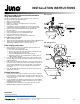
INSTALLATION for Electrical feed at outlet box.
Use No. 12 AWG solid copper wire only. Rated 120V, 60Hz, 20A.
For standard ceiling using R21 End Feed:
1. Make sure that power is OFF.
2. Pull junction box wires through mounting strap hole. Attach mounting
strap to existing junction box with enclosed screws.
3. Insert feed connector fully into Trac with arrow pointing toward
Trac polarity line and secure with set screw.
4. Attach Trac to ceiling (or wall) following instructions supplied
with the Trac section.
5. Pull junction box wires through feed connector and nipple.
6. Secure feed connector to mounting strap with lock nut and
nipple provided.
7. Fasten positive wire to screw terminal marked “P”.
8. Fasten white wire (neutral) to screw terminal marked “N”.
9. Connect ground wire to ground screw.
10. Replace cover and secure with screw.
11. Attach trac to ceiling with toggle bolts or screws.
For T-Bar or Drop Tile
1. Make sure power is OFF.
2. Follow electrical feed installation instructions for R36 T-Bar End Feed.
3. Attach trac to ceiling with R37F T-Bar Clips or R37D Drop Ceiling
Clips. Maximum distance between clips is 4’.
(Continued on back)
FOR JUNO R SERIES TRAC SECTIONS
IMPORTANT SAFETY INSTRUCTIONS
1 of 2
1300 S. Wolf Road • Des Plaines, IL 60018 • Phone 800-323-5068 • Visit us at www.acuitybrands.com/juno-trac
©2017 Acuity Brands Lighting, Inc. Rev 3/17 P3071
INSTALLATION INSTRUCTIONS