
Installation Guide


R23 Mini-Connector
Joins two Trac sections end-to-end. Use to continue a straight run.
1. Make sure main power is OFF.
2. Insert Mini-Connector fully into Juno Trac with polarity arrow pointing
towards Trac polarity line. Secure with set screws.
3. Attach Trac to ceiling (or wall) following instructions supplied with the
Juno Trac Section.
R20 Flexible Connector
Joins two Trac sections at any angle between 0 and 90 degrees.
Use for inside or outside corners and for changing run direction less than 90°.
1. Make sure main power is OFF.
2. Insert Flexible Connector fully into Juno Trac with polarity arrow pointing
toward Trac polarity line. Secure with set screws.
3. Bend Flexible Connector to desired angle.
4. Attach Trac to ceiling (or wall) following instructions supplied with the
Juno Trac section.
R24 Adjustable Connector
(Can also use as electrical feed from Junction Box)
Joins two Trac sections at 90° or as a straight run. Factory assembled to make
a 90° turn. If opposite angle is required, cover must be removed and connector
ends rotated to new position, then replace cover. For straight run use, remove
L cover, straighten connector and attach straight cover.
1. Make sure main power is OFF.
2. Insert Adjustable Connector fully into Juno Trac with polarity arrow
pointing toward Trac polarity line. Secure with set screws.
3. Attach Trac to ceiling (or wall) following instructions supplied with the
Juno Trac section.
For using Adjustable Connector to power track from a Junction Box:
1. Attach Juno Junction Box Cover T27 (not supplied) to Adjustable
Connector.
a. Punch out screw holes from Junction Box Cover T27.
b. Remove Adjustable Connector cover.
c. Secure Adjustable Connector flush to Junction Box Cover T27
using nipple and locknuts supplied with Junction Box Cover.
2. Insert feed connector fully into Trac with polarity arrow pointing toward
Trac polarity line. Secure with set screw.
3. Attach Trac to ceiling (or wall) following instructions supplied with the
Trac section.
4. Pull junction box wires through Junction Box Cover nipple.
5. Secure Junction Box Cover/Adjustable Connector assembly to existing
junction box using screws supplied with Junction Box Cover.
6. Fasten positive wire to screw terminal marked “P”.
7. Fasten white wire (neutral) to screw terminal marked “N”.
8. Replace Adjustable Connector cover and secure with screw.
Juno R series connectors, electrical feeds and accessories are to be used only with Juno R Series Trac. Some Juno R Series Connectors
can also be used as Electrical Feeds as noted. All Juno Trac Components are both mechanically and visually polarized to assure proper
connections and to simplify installation.
• Trac face has polarity line indicating positive side
• Trac connectors have embossed arrow which must point towards the Trac polarity line when installed.
Important: Completely read instructions before attempting installation. Electrical Rating: 120V, 60Hz and 20 amp max
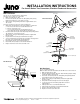
Polarity Line
Polarity Arrows
Polarity
Arrow
R24 Adjustable Connector
R24
Polarity Arrow
Set Screws
Polarity LIne
Cover
Polarity
R20 Flexible Connector
V2020WH
Polarity Line
Set Screws
Polarity Arrow
Polarity
R23 Mini-Connector
Polarity Arrow
Polarity LIne
Set Screws
Exisiting
Junction Box
(not Included)
Junction Box
Cover T27
Adjustable
Connector
Locknut
(supplied with T27)
Nipple
(supplied with T27)
Locknut
Screws
(supplied with T27)
For Juno R Series Trac Connectors, Electrical Feeds and Accessories
INSTALLATION INSTRUCTIONS
1 of 4
1300 S. Wolf Road • Des Plaines, IL 60018 • Phone 800-323-5068 • Visit us at www.acuitybrands.com/juno-trac
©2017 Acuity Brands Lighting, Inc. Rev 3/17 P3069