
Installation Guide
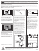

Juno Type TC & PL fixtures are designed for
installations where housing and J-Box will
not come into contact with insulation.
Insulation must be spaced 3" away from the
housing and J-Box (Fig. 1)*. Blinking light
after installation indicates that improper bulb
or trim is being used or that fixture has been
improperly covered with insulation.
3"
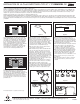
Step 1. Locate center of proposed open-
ing on ceiling and use template to mark
and accurately cut a 4-3/8" (for 4" hous-
ings), 5-1/2" (for 5" housings) or a 6-5/8"
(for 6" housings) opening. For sloped
ceiling housings, an oval hole template is
provided. (Fig. 3).
Step 2. Follow steps 1-4 under electrical
connection.
Step 3. Press housing through ceiling
opening so it is flush to ceiling (Fig. 4).
Push retention clips outwards until each
clip tab clicks into position. On some
housings, a single “T” slot clip is provid-
ed for additional support. Insert clip
through “T” slot from inside housing,
force clip down with screwdriver until clip
is seated. Secure clip by tightening
screw. (Fig. 5).
(Note: To remove housing from ceiling, push
tab on clip upward to disengage)
.
Step 4. Install trim using coil, leaf,
torsion, or push-in springs as provided
(Fig. 6). Remove socket paint protector
cover and install proper lamp (light bulb)
as listed on housing label.
TYPE IC & TC REMODEL RECESSED HOUSING INSTALLATION INSTRUCTIONS
WARNING: For your safety, read and understand instructions completely before starting installation. Before wiring to power supply, turn off
electricity at the fuse or circuit breaker box.
NOTE: Juno recessed fixtures are designed to meet the latest NEC requirements and are listed in full compliance with UL1571, 1570 or 1598.
Before attempting installation of any recessed lighting fixture, check your local electrical building code. This code sets the wiring and installation
requirements for your locality and should be understood before starting your work.
NOTE: Use of Non-Juno trims voids Juno warranty.
TYPE TC & PL for Non-Insulated Ceilings
Installation Steps Electrical Connection Instructions
Step 1. Provide electrical service accord-
ing to your local electrical code to the
wiring box located on the remodel hous-
ing. Supply wire insulation must be rated
for at least 90°C.
Step 2. Remove wiring box cover. Remove
the appropriate knock-out to connect flexi-
ble metal conduit or non-metallic cable to
wiring box with proper connectors (by oth-
ers) (Fig. 7).
Step 3. Connect supply wires to fixture
wires with proper size wire nuts (not sup-
plied), so as to cover all bare current-carry-
ing conductors. Connect black fixture wire
to hot, white fixture wire to neutral and
green fixture wire to ground (Fig. 8).
Step 4. Place all wiring and connections
back in wiring box and replace cover.
TYPE IC for Insulated Ceilings
Figure 1
Figure 2
Figure 3
Black
Lamp Socket
Thermal Protector
White
120V
Figure 8
Figure 5
Figure 4
Figure 6
Figure 7
1300 South Wolf Road • Des Plaines, IL 60017 • (847) 827-9880 • www.junolightinggroup.com
© Juno 2005 Printed in USA Rev. 3/05
#P3060
*In Canada, when insulation is present, Type IC fixtures
must be used.
Juno Type IC fixtures are designed for direct
contact with insulating materials which are
approved for this application (Fig. 2). Blinking
light after installation indicates that improper
bulb or trim is being used.
Use Juno Air-Loc Gaskets or Air-Loc Rated
Trims with Juno IC housings for additional
energy savings and to comply with
Washington State and other energy codes.