
Installation Guide

© 2011 Juno Lighting LLC Rev 3/12 P3217 pg 2 of 2
INSTALLATION INSTRUCTIONS
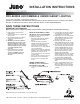
MOUNTING FIXTURE
1. Place fixture in desired position.
2. Drive fixture MOUNTING SCREWS
securely. Mounting screws are suitable for
cabinet bottoms 3/8" or thicker. Use shorter
screws for cabinet bottoms thinner than 3/8".
3. In some installations it may be desired to
drill a pilot hole for the screws. Place the
fixture in the desired position and drive
MOUNTING SCREWS a small amount to
impart a small reference point for drilling.
4. Make sure that all unused electrical ports
on the ends of the fixture are safely
protected with ELECTRICAL PORT
COVERS (two provided with each fixture).
5. Re-energize electrical circuit at service
panel.
6. Fixture has a two-position switch:
ON/OFF.
JOINING MULTIPLE FIXTURES
1. WARNING: In multiple fixture
installations do not electrify fixture group
until all electrical connections have been
securely mounted. Electrical port covers
must be installed in all open ports at the
completion of installation.
2. Fixtures can be joined together using
FIXTURE JOINER (one provided with each
fixture) or with JUMPER CORD accessory
(Cat. No. JC3, sold separately).
3. WARNING: The total number of fixtures
that can be joined together and powered
from one electrical feed port is governed
by the total current per electrical feed
point (5A MAXIMUM).
WARRANTY
Juno Lighting Group provides five year limited warranty on LED components from date of purchase. Juno Lighting Group’s obligation
is expressly limited to repair or replacement, without charge, at Juno Lighting Group’s factory after prior written return authorization has been
granted. This warranty shall not apply to products which have been altered or repaired outside of Juno Lighting Group’s factory. This warranty
is in lieu of all other warranties, expressed or implied, and without limiting the generality of the foregoing phrase, excludes any implied warranty
of merchantability. Also, there are no warranties which extend beyond the description of the product on the company’s literature setting forth
terms of sale.
Product Services Phone (888) 387-2212
1300 South Wolf Road • Des Plaines, IL 60018 • Phone 800-323-5068 • www.junolightinggroup.com
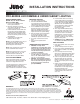
PRO-SERIES LED DIMMABLE UNDERCABINET LIGHTING
4. First mount fixture that receives incoming
electrical supply. With a small screwdriver
remove ELECTRICAL PORT COVERS as
needed. When using FIXTURE JOINER to
add fixtures make sure JOINER is fully
seated in both fixtures. Fixtures should fit
fully and squarely end-to-end when
mounting is complete.
5. When using JUMPER CORD accessory,
make sure plugs on both ends are fully
inserted into ports on both fixtures. There
should be some slack in the JUMPER
CORD so that the electrical connectors are
not stressed in any way. Use cord clips
(provided), as desired, to keep cord safely
snug to mounting surface.
6. WARNING: Do not use JUMPER CORD
as a means to turn fixtures on and off.
LENS CLEANING
1. Before opening fixture make sure it has fully
cooled down.
2. Turn off electrical power at service panel.
3. Lower lens by pushing LENS RETENTION
BAR towards rear of fixture. Lens will swing
downward.
4. Lens can be fully removed for cleaning.
While lens is in straight down position, grasp
right side lens end cap and push rearward
about 1/4". Pull down and remove lens.
5. Clean lens only with warm water and a mild
detergent solution. Do not use abrasive
powders or petroleum solvents to clean
lens. Dry lens completely before re-inserting
into fixture.
6. Replace lens by first inserting pin into hole
in left side of fixture. Push right pin up into
slot on right side of fixture and pull lens
forward about 1/4" until it stops. Swing lens
back and up into fixture while
simultaneously pushing lens retention bar
rearward. Release lens retention bar to
secure lens.
WIRING CONNECTIONS –
UPLED 14", 20" & 30" Fixtures
Armored Cable (BX)
1. Loosen screw on ROMEX PLATE.
Remove plate and discard.
2. Mount die-cast aluminum electrical
connector to the flat side of the CONDUIT
PLATE. Securely tighten nut.
3. Push BX cable into connector. Make sure
BX cable has a properly installed plastic
insulating bushing (not provided). Tighten
clamp screws securely making sure that
BX cable remains fully seated in connector
during tightening.
4. Perform steps 3-7 from NM cable
instructions listed on page 1.
NOTE: In some BX installations there may not
be a separate grounding wire provided.
Grounding is achieved through the spiral
wound metal jacket of the BX cable.
NOTE: The die-cast aluminum connector can
also be used with NM cable if desired.
NOTE: Two die-cast connectors can be used
for loop feed supply wiring (14", 22" & 30"
units) if desired. (For second die-cast
connector, order accessory ULH-CONN.)
120V FIXTURE DIMMING*
Fixtures are dimmable with the use of most
120V incandescent, magnetic low voltage and
electronic low voltage wall box dimmers.
* Consult Technical Services at (888) 387-2212
or www.junolightinggroup.com for dimmer
compatibility. Electronic low voltage dimmers
require a neutral wire connection in the wall box.