
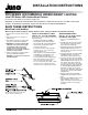
Installation Guide

1300 S. Wolf Road • Des Plaines, IL 60018 • Phone 800-323-5068 • Visit us at www.acuitybrands.com/juno-undercabinet
©2017 Acuity Brands Lighting, Inc. Rev 5/17 P3977
1 of 2
INSTALLATION INSTRUCTIONS
IMPORTANT SAFEGUARDS:
When using electrical equipment, always adhere to basic safety precautions including the following:
SAVE THESE INSTRUCTIONS
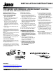
PRO-SERIES LED DIMMABLE UNDERCABINET LIGHTING
Juno UPS Series LED Undercabinet Fixtures
For use with 120V, 60Hz electrical power supply only.
WARNING: TO PREVENT OVERHEATING AND ELECTRICAL SHOCK DO NOT INSTALL IN SMALL ENCLOSED
SPACES. TO PREVENT ELECTRICAL SHOCK DO NOT INSTALL IN WET ENVIRONMENTS.
1. Read all of these instructions before installing
fixture.
2. Keep these instructions in a safe place for
future reference.
3. Only qualified electricians in accordance with
local codes should perform all installations.
4. WARNING: For hard wire installation (NM
& BX) make sure electrical power supply
for installation circuit is shut down at
electrical service panel before starting
installation. Do not re-energize circuit until
installation is fully completed.
5. Fixture is designed to be electrically grounded
for hard wire (NM & BX) installations.
WARNING: To prevent shock closely follow
grounding directions.
WIRING CONNECTIONS –
UPS 14", 22", 30" & 40" Fixtures
Non-Metallic Cable (NM)
1. Loosen screw on ROMEX PLATE and
remove.
2. Push NM supply cable through rectangular
wire grip in plate so outer jacket of cable
projects about 3/4" through plate.
3. Inside fixture are three wires with PUSH-IN
WIRE CONNECTORS fitted to each end.
Carefully pull these out of fixture. Do not pull
with excessive force.
4. Using strip length guide on PUSH-IN WIRE
CONNECTORS make sure lengths of
exposed wire on supply cable are correct.
5. Insert each of the three wires from the NM
supply cable into each of the three PUSH-IN
WIRE CONNECTORS with respective color
wires. Black to black, white to white, and
green (or bare copper wire) to green. Make
sure that feed wires are securely gripped by
the PUSH-IN WIRE CONNECTORS and
that with the exception of a bare ground
wire, none of the supply wires show exposed
wire where they enter the PUSH-IN WIRE
CONNECTORS.
6. Neatly push wires and PUSH-IN WIRE
CONNECTORS into opening in back of the
fixture.
7. Properly engage ROMEX PLATE in back of
fixture and tighten screw. Do not over
tighten screw. Make sure that lock washer is
installed under head of screw for proper
grounding.
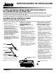
WAYS TO ELECTRICALLY FEED
UPS 14", 22", 30" & 40" FIXTURES
Electrical power can be brought to the fixture using
different techniques:
• Non-Metallic Cable (NM) using ROMEX
PLATE (provided) and mounted on fixtures.
• Armored Cable (BX) using optional CONDUIT
PLATE and die-cast aluminum electrical
connector (provided loose).
• Connections can also be made using fixture
knockouts (14", 22", 30" & 40" units) and
connector supplied loose.
• Wiring module accessory UDWM, UDWMOC
or UDWMOC RS (sold separately) can be
used for forward mount applications if
necessary to allow for remote supply wiring or
when remote occupancy sensor is desired.
Can be used with all (5) fixture lengths.
• Since 9" unit cannot be direct wired, a wiring
module accessory or another UPS fixture
should be used in conjunction with a 9" unit.
Wiring methods shown for use with UPS
14", 22", 30" and 40" fixtures only.