
User's Manual

Rev0.0
Page3of
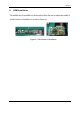
4. Description of operations
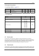
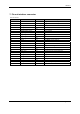
4.1 Operating Conditions ( 5 V 450 mA)
Symbol Parameter Min. Typ Max Unit
VCC Supply Voltage 4.7 5.0 5.25 V
Temp Operating Temperature 0 25 60 °C
4.2 RF Information
Parameter Value Unit
Modulation QPSK
RF Frequency range (band)
2400 – 2483.5
5150 – 5250
5725 – 5875
MHz
Ch1 – 2412
Ch2 – 2436
Ch3 – 2464
Ch4 – 5180
Ch5 – 5210
Ch6 – 5240
Ch7 – 5736
Ch8 – 5726
Ch9 – 5814
MHz
Audio Latency
20ms
Audio Bit Resolution
16bit
Audio Sampling Rate
48ksps
Note: Country/ Region dependent.
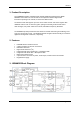
4.3 Receive mode
In receive mode, antenna diversity is supported. The single ended output of the TR switch is
connected to the RF LNA input through Diplexer and matching networks. Filtering and amplification is
all performed by the radio transceiver. The gain setting is controlled by the BB. The analog IQ outputs
are sampled by the BB by its integrated 22Msps dual channel 8bit ADC. This received data is
demodulated and fed to the audio processing engine controlling the audio function.
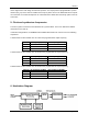
4.4 Transmit mode
In transmit mode, the audio engine transforms the audio data into packetized digital IQ signals. These
are in turn pulse-shaped before conversion by a 10bits 44Msps DAC to match to the analog IQ inputs
of the radio IC. The radio IC has programmable baseband filters to lower the RF spectrum side lobes
9
Using RF Frequency