
User's Manual

Rev0.0
Page4of
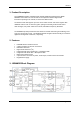
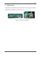
and to suppress the DAC image and the DAC spurious. The output power is programmable. A power
detector (PD_out) on the radio IC enables close-loop TX power control. The differential RF PA outputs
are connected via a baluns and Diplexer to a transmit/receive switch with TX diversity option to the RF
connectors.
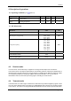
5. Clock and synthesizer frequencies
The main crystal is connected to the Baseband IC crystal oscillator. This in turn buffers this 44MHz
and feeds it to the radio IC.
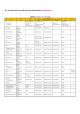
In standard configurations, the DARR83 based DWPCIe83 module’s RF section runs at the following
frequencies:
2.4GHz Band: The RF oscillator runs at 2 times the programmed RF output frequency.
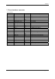
Channel RF frequency (in MHz) VCO frequency (in MHz)
1 2412 4824
2 2438 4876
3 2464 4928
5.2GHz Band: The RF oscillator runs at 2/3 times the programmed RF output frequency.
Channel RF frequency (in MHz) VCO frequency (in MHz)
1 5180 3453.33
2 5210 3473.33
3 5240 3493.33
5.8GHz Band: The RF oscillator runs at 2/3 times the programmed RF output frequency.
Channel RF frequency (in MHz) VCO frequency (in MHz)
1 5736 3824
2 5762 3841.33
3 5814 3876
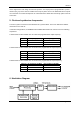
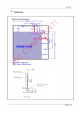
6. Modulation Diagram
9