QUARTZ GLASS TUBE PATIO HEATER INSTRUCTION MANUAL Keep the instructions for future reference 14 0063
WARNlNG SAFETY RULES PLEASE READ THE FOLLOWING SAFETY RULES PRlOR TO OPERATION OF THE HEATER FOR YOUR SAFETY If you smell gas: 1ˊShut off gas to the appliance. 2ˊExtinguish any open flame. 3ˊIf odor continues, immediately call your gas supplier or your fire Department. FOR YOUR SAFETY 1.Do not store or use gasoline or other flammable vapors and liquids in the vicinity of this or any other applianceˊ 2.
warning Read the instructions before installation and use.
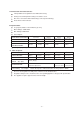
TABLE OF CONTENTS Caution ………………………………………………………. 1 Heater Stand and Location ………………………………… 2 Gas Requirements ………………………………………….. 2 Leakage Test ………………………………………………… 2 Operation and Storage ……………………………………... 3 Cleaning and Care ………………………………………….. 4 Parts and Specifications ..………………………………….. 4 Assembly Parts and Procedures ………………………….. 6 Problems Check List ………………………………………...
CAUTION PLEASE READ CAREFULLY THE FOLLOWING SAFETY GUIDELINES BEFORE OPERATION. Do not use the patio heater for indoors, as it may cause personal injury or property damage. This outdoor heater is not intended to be installed on recreational vehicles and/or boats. Installation and repair should be done by a qualified service person. Improper installation, adjustment, alteration can cause personal injury or property damage. Do not attempt to alter the unit in any manner.
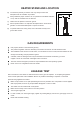
HEATER STAND AND LOCATION adequate fresh air ventilation is provided. 100 cm Always maintain proper clearance to non protected combustible materials 100 cm CEILING The heater is primarily for outdoor use only. Always ensure that Heater must be placed on level firm ground. Never operate heater in an explosive atmosphere like in areas where gasoline or other flammable liquids or vapors are stored. WALL i.e. top 100 cm and sides 100 cm minimum.
maximum Warning˖check that no broken on the glass is found before operation.
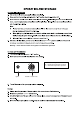
CLEANING AND CARE • Wipe off powder coated surfaces with soft, moist rag. Do not clean heater with cleaners that are combustible or corrosive. • Remove debris from the burner to keep it clean and safe for use. • Cover the burner unit with the optional protective cover when the heater is not in use.
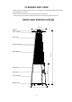
A. Construction and characteristics Transportable terrace/garden heater with tank housing. Casing in steel with powder-coating or in stainless steel. Gas hose connections with metal clamp (screw caps for Germany). Heat emission from reflector. B. Specifications Use propane,butane or their mixtures gas only. Max. wattage: 13000 watts Min.
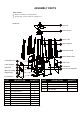
ASSEMBLY PARTS Tools needed: Philips screwdriver w/ medium blade Spray bottle of soap solution for leakage test Parts List: Control Box Assy J Lower Support K Block Belt L Wheel Assembly M Bottom Plate N Led controller O PART A B C D E F G H I J K A Reflector B Flame Screen C Glass Tube D Upper Support E Protective Guard F Black Silicone Ring G Side Panel H Front Panel I DESCRIPTION Reflector Flame Screen Glass Tube Upper Support Protective Guard Black Silicone Ring Side Panel
ASSEMBLY PARTS HARDWARE CONTENTS (shown actual size) AA BB Wing nut Qty. 3 GG CC Stud Qty. 3 Small flat ZDVKHU ĭ Qty. HH 6FUHZ 0 ; Qty. NN DD JJ )L[LQJ %UDFNHW Qty. 4 ´ 6FUHZ Qty. 42 :UHQFK Qty. 1 LL Philips VFUHZGULYHU Qty. 1 PP Long Stem Lighter Qty.1 -7- 0 Flange nut Qty. 4 %ROW 0 ; Qty. 4 KK OO Chain Qty.1 FF EE Wafer Qty.1 MM Knob Qty. 1 6FUHZ 0 ; Qty.
ASSEMBLY PROCEDURES 1. Assemble the wheel assembly to the bottom plate. Fix the wheel assembly to the bottom plate using 4pcs bolt M6X12 and 4pcs flange nut M6. 1 Hardware Used EE Bolt M6 X 12 x4 FF M6 Flange nut x4 JJ Wrench x1 EE M FF 2 2. Insert the pins of the base to the holes of lower support, press to secure the pins. Using 4pcs screw M5x12 to secure the lower support and base. Insert the pins of the control box assy to the holes of upper support, press to secure the pins.
3.Assemble block belt. Fix the block belt to the 2pcs of lower support behind the front door,using 2pcs screw M5X12. 3 Hardware Used GG Screw M5 X 12 KK Philips screwdriver x2 x1 L GG 4. Assemble the middle support. Insert the 4pcs upper support to the lower support. Secure them with 8pcs screw 3/16”.
5. Assebmle the flame screen to the upper support. Secure the flame screen to the upper support using 8pcs screw 3/16”. 5 B Hardware Used DD 3/16” Screw x8 KK Philips screwdriver x1 6. Assemble the reflector onto the flame screen. Screw the 3pcs stud on the flame screen, put 3pcs washer Φ6 onto the top of stud, then put the reflector onto the stud, secure them with 3pcs washer Φ6 and 3pcs wing nut.
7. Carefully install the glass tube by lifting up and inserting through the center hole in the upper plate. Ensure the black silicone ring is attached to the lower edge of the glass tube as illustrated. Slide the glass tube through the hole of the lower plate cover and onto the middle plate. Check and ensure that the glass tube is positioned properly and is completely covering the center hole of the middle plate.
9. Attach the three side panels to the heater using 18pcs screw 3/16”. Note : Do not cover the front side where the control knob is. 9 Hardware Used DD 3/16” Screw x 18 KK Philips screwdriver x1 10. Assemble the chain and wafer to the inside of front panel with M4x10 screw, then install the knob to M4x10 screw. Hang the chain to the hole on the control box assy and put the pothook of front panel to the holes of bottom plate.
11. Propane Only-Proper Hose Connection. WARNING! Ensure the hose does not contact any high temperature surfaces, or it may melt and leak causing a fire. After the cylinder is placed inside the heater, secure the cylinder with block belt tightly. 11 12. Leak Check. WARNING! of the gas system is replaced. EĞǀĞƌ ƵƐĞ ĂŶ ŽƉĞŶ ŇĂŵĞ ƚŽ ĐhĞĐŬ ĨŽƌ ŐĂƐ ůĞĂŬƐ͘ Ğ ĐĞƌƚĂŝŶ ŶŽ ƐƉĂƌŬƐ Žƌ ŽƉĞŶ ŇĂŵĞƐ ĂƌĞ WARNING! in the area while you check for leaks.
ASSEMBLY INSTRUCTIONS 12. LED belt box and battery box installation. 12-1. The normal position of block chip like 12 figure a. 12-2. Adjust the position of block chip like figure b. Pull out the LED belt box. 12-3. When chang the batteries, first take out the LED belt box and then battery box, after that open the battery box and Figure a change the batteries like figure c.
ASSEMBLY INSTRUCTIONS Operation Instructions of Controller 1.Specifications: Working temperature:-20-60ć Supply voltage:DC12V Product size:L62×W35×H23mm Package size:L105×W65×H55mm Net weight:50g Gross weight:70g Output:Three CMOS drain-open output Connecting Mode:Common anode Max Ioad current:2 A each color 2.
PROBLEMS CHECK LIST PROBLEM PROBABLE CAUSE SOLUTION Pilot will not light Gas valve may be OFF Turn the gas valve ON Tank fuel empty Refill LPG tank Opening blocked Clean or replace opening Air in supply system Purge air from lines Loose connections Check all fittings Debris around pilot Clean dirty area Loose connections Tighten connections Thermocouple bad Replace thermocouple Gas leak in line Check connections Lack of fuel pressure Tank near empty. Refill LPG tank.