INSTRUCTION MANUAL ALL MODE MULTI-BAND TRANSCEIVER TS-2000 TS-2000X TS-B2000 KENWOOD CORPORATION © B62-1221-00 (K) 09 08 07 06 05 04 03 02 01 00
THANK YOU THANK YOU SUPPLIED ACCESSORIES Thank you for choosing this KENWOOD TS-2000(X)/ TS-B2000 transceiver. It has been developed by a team of engineers determined to continue the tradition of excellence and innovation in KENWOOD transceivers. After carefully unpacking the transceiver, identify the items listed in the table. We recommend you keep the box and packing material below in case you need to repack the transceiver in the future.
MODELS COVERED BY THIS MANUAL NOTICE TO THE USER The models listed below are covered by this manual. One or more of the following statements may be applicable for this equipment. TS-2000 : HF/ VHF/ UHF All-mode Multi-band Transceiver TS-2000X : HF/ VHF/ UHF/ 1.2 GHz All-mode Multi-band Transceiver TS-B2000 : HF/ VHF/ UHF All-mode Multi-band Transceiver As for TS-B2000, refer to the on-line help how to operate and control the transceiver.
PRECAUTIONS Please observe the following precautions to prevent fire, personal injury, and transceiver damage: • Connect the transceiver only to a power source described in this manual or as marked on the transceiver itself. • Route all power cables safely. Ensure the power cables can neither be stepped upon nor pinched by items placed near or against the cables. Pay particular attention to locations near AC receptacles, AC outlet strips, and points of entry to the transceiver.
CONTENTS PRECAUTIONS I CHAPTER 1 INSTALLATION ANTENNA CONNECTION ....................................... 1 GROUND CONNECTION ........................................ 2 LIGHTNING PROTECTION ..................................... 2 DC POWER SUPPLY CONNECTION ...................... 2 UTILIZING THE BAIL ............................................... 2 REPLACING FUSES ............................................... 2 ACCESSORY CONNECTIONS ............................... 3 FRONT PANEL ..........................
CHANGING KEYING SPEED ............................ 42 AUTO WEIGHTING ........................................... 42 Reverse Keying Weight ................................ 42 BUG KEY FUNCTION ....................................... 43 CW MESSAGE MEMORY ................................. 43 Storing CW Messages .................................. 43 Checking CW Messages without Transmitting .................................................. 43 Transmitting CW Messages ..........................
PARTIAL RESET ................................................... FULL RESET ......................................................... SWITCHING ANT 1/ ANT 2 ........................................ FREQUENCY LOCK FUNCTION .............................. BEEP FUNCTION...................................................... DISPLAY DIMMER .................................................... PROGRAM FUNCTION BUTTON ............................. QUICK DATA TRANSFER .........................................
INSTALLATION |nstall and connect an antenna system {page 1}. Install and connect a DC power supply {page 2}. Install a ground system that satisfies DC and RF grounding requirements {page 2}. Connect all accessories to the transceiver {pages 3, 60}. Accessories include the following: Install lightning protection to protect the antenna system, your personal safety, and your property {page 2}.
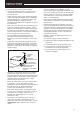
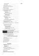
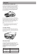
1 INSTALLATION DC POWER SUPPLY CONNECTION In order to use this transceiver, you need a separate 13.8 V DC power supply that must be purchased separately. Do not directly connect the transceiver to an AC outlet. Use the supplied DC power cable to connect the transceiver to a regulated power supply. Do not substitute a cable with smaller gauge wires. The current capacity of the power supply must be 20.5 A peak or more. Fuse holders Black Red TS-2000/ TS-2000X TS-B2000 DC 13.
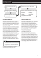
1 INSTALLATION ACCESSORY CONNECTIONS FRONT PANEL ■ Headphones (PHONES) Connect monaural or stereo headphones having a 4 to 32 Ω impedance. This jack accepts a 6.3 mm (1/4") diameter, 2-conductor (mono) or 3-conductor (stereo) plug. After connecting the headphones, you will hear no sound from the internal (or optional external) speaker. Headphone ■ Microphone (MIC) Connect a microphone having an impedance between 250 and 600 Ω.
YOUR FIRST QSO (HF/ 50 MHz band) Are you ready to give your TS-2000(X) a quick try? Reading these two pages should get your voice on the air in your first QSO on the HF/ 50 MHz band shortly. The instructions below are intended only for a quick guide. If you encounter problems or there is something you don’t understand, read the detailed explanations given later in this manual.
2 YOUR FIRST QSO (HF/ 50 MHz band) TRANSMITTING 4 9 CW TUNE RIT ALT XIT HF/VHF/UHF ALL MODE MULTI BANDER TS-2000 PF F LOCK A ATT PRE LEVEL LEVEL VOX PROC ANT1/2 SEND AT 2 3 PHONES CLEAR MAIN LEVEL SUB CH1/REC CH2/ REC CH3/REC N. A.N . MANUAL B.C . LO/ WIDTH 1 2 3 TONE/SEL METE R CTCSS/SEL 4 5 6 NB/LEVEL AGC /OFF FINE/STE P 7 8 . 0 DCS/SEL SHIFT/OFFS ET 9 ENT HI/ SHIFT CAR MIC TX MONI PWR DELAY KEY MENU REV CW FSK NAR FM AM CLR TFSET MAIN REV M/S A/B SUB SEL SG.
YOUR FIRST QSO (VHF/ UHF band) If your primary operating band is VHF (144 MHz) or UHF (430/ 440 MHz), the TS-2000(X) can also serve you as a powerful All-mode VHF/ UHF transceiver. The instructions below are intended only for a quick guide to get you up on the air on the VHF/ UHF band. If you encounter problems or there is something you don’t understand, read the detailed explanations given later in this manual.
3 YOUR FIRST QSO (VHF/ UHF band) TRANSMITTING CW TUNE RIT ALT XIT HF/VHF/UHF ALL MODE MULTI BANDER TS-2000 PF F LOCK A ATT PRE LEVEL LEVEL VOX PROC ANT1/2 SEND AT MAIN LEVEL SUB CH1/REC CH2/ REC CH3/REC N. A.N . MANUAL B.C . LO/ WIDTH 1 2 _ 3 TONE/SEL METE R CTCSS/SEL 4 5 6 NB/LEVEL AGC /OFF FINE/STE P 7 . 8 DCS/SEL SHIFT/OFFS ET 0 9 ENT HI/ SHIFT MIC TX MONI PWR DELAY KEY MENU REV CW FSK NAR FM AM CLR MAIN MANUAL BC RF GAIN QUICK MEMO AUTO LSB USB CAR TFSET C.IN CALL R.
GETTING ACQUAINTED FRONT PANEL 2 1 CW TUNE RIT ALT XIT HF/VHF/UHF ALL MODE MULTI BANDER TS-2000 PF 6 7 8 PHONES CLEAR MAIN LEVEL N. A.N . B.C . 10 LO/ WIDTH 1 2 3 TONE/SEL METE R CTCSS/SEL 4 5 6 NB/LEVEL AGC /OFF FINE/STE P 7 . 8 DCS/SEL SHIFT/OFFS ET 0 HI/ SHIFT 9 ENT AUTO LSB USB RIT/SUB _ CAR MIC TX MONI PWR DELAY KEY MENU REV CW FSK NAR FM AM CLR MAIN MANUAL BC RF GAIN QUICK MEMO TFSET C.IN CALL R. MANUAL MIC SUB CH1/REC CH2/ REC CH3/REC LEVEL 9 9.
4 GETTING ACQUAINTED 16 CW TUNE RIT ALT XIT HF/VHF/UHF ALL MODE MULTI BANDER TS-2000 PF F LOCK A ATT PRE LEVEL LEVEL VOX PROC ANT1/2 SEND AT MAIN LEVEL SUB CH1/REC CH2/ REC CH3/REC N. A.N . MANUAL B.C . LO/ WIDTH 1 2 _ 3 TONE/SEL METE R CTCSS/SEL 4 5 6 NB/LEVEL AGC /OFF FINE/STE P 7 8 . 0 DCS/SEL SHIFT/OFFS ET 9 ENT MIC TX MONI PWR DELAY KEY HI/ SHIFT DISP 14 MENU REV CW FSK NAR FM AM CLR MAIN MANUAL BC RF GAIN QUICK MEMO AUTO LSB USB CAR TFSET C.IN CALL R.
4 GETTING ACQUAINTED 20 19 29 25 27 28 33 CW TUNE RIT ALT XIT HF/VHF/UHF ALL MODE MULTI BANDER TS-2000 PF F LOCK A ATT PRE LEVEL LEVEL VOX PROC ANT1/2 SEND AT MAIN LEVEL SUB CH1/REC CH2/ REC CH3/REC N. A.N . MANUAL B.C . LO/ WIDTH 1 2 3 TONE/SEL METE R CTCSS/SEL 4 5 6 NB/LEVEL AGC /OFF FINE/STE P 7 8 . 0 DCS/SEL SHIFT/OFFS ET HI/ SHIFT 9 ENT AUTO LSB USB CAR _ MIC TX MONI PWR DELAY KEY REV CW FSK NAR FM AM CLR MAIN MANUAL BC RF GAIN QUICK MEMO MENU TFSET C.IN CALL R.
4 GETTING ACQUAINTED 41 36 35 34 39 HF/VHE/UHF ALL MODE MULTI BANDER TS-2000 CLEAR SUB MAIN LEVEL CH1/REC CH2/ REC CH3/REC N. . A.N MANUAL B.C . LO/ WIDTH 1 RIT/SUB _ 2 3 TONE/SEL METE R CTCSS/SEL 4 5 6 NB/LEVEL AGC /OFF FINE/STE P 7 . 8 DCS/SEL SHIFT/OFFS ET 0 HI/ SHIFT 9 ENT CAR MIC TX MONI PWR DELAY KEY MENU REV CW FSK NAR FM AM CLR DISP MAIN MANUAL BC RF GAIN QUICK MEMO AUTO LSB USB TFSET C.IN CALL R. LEVEL MIC 9.6k STA CON + P.C.
4 GETTING ACQUAINTED 54 55 45 CW TUNE RIT ALT XIT HF/VHF/UHF ALL MODE MULTI BANDER TS-2000 PF F LOCK A ATT PRE LEVEL LEVEL VOX PROC ANT1/2 SEND AT CLEAR MAIN LEVEL SUB CH1/REC CH2/ REC CH3/REC N. A.N . MANUAL B.C . LO/ WIDTH 1 2 3 TONE/SEL METE R CTCSS/SEL 4 5 6 NB/LEVEL AGC /OFF FINE/STE P 7 8 . 0 DCS/SEL SHIFT/OFFS ET 9 ENT HI/ SHIFT AUTO LSB USB CAR 47 9.
4 GETTING ACQUAINTED REAR PANEL 1 2 ANT 2 2 3 9 6 5 8 AT ANT 144 1 ANT 1.2G ANT 1 KEY PADDLE GND COM 4 PANEL EXT. SP2 EXT. SP1 8Ω 8Ω 10 ANT 430 EXT. CONT ACC2 12 13 11 DC 13.8V REMOTE 14 HF RX ANT 15 7 q ANT 1 and ANT 2 connectors o COM connector Connect your primary HF/ 50 MHz antenna to ANT1. If you are using 2 antennas for the HF/ 50 MHz band, connect the secondary antenna to the ANT2 connector.
4 GETTING ACQUAINTED DISPLAY 1 S 6 1 5 3 10 PWR ALC 7 9 20 50 25 40 8 12 14 16 7 11 13 15 60dB 100W% FILTER 2 3 4 5 10 9 q METER o While receiving, serves as an S-meter to measure and display the received signal strength. While transmitting, serves as a power meter plus an ALC meter, an SWR meter, or a Speech Processor compression meter. The Peak Hold function holds each reading for approximately 2.5 seconds. Shows the memory channel number for the main transceiver.
4 GETTING ACQUAINTED 18 20 22 24 17 19 21 23 26 S 1 PWR ALC 3 10 5 7 25 9 20 50 40 30 25 27 28 29 60dB 100W% FILTER 31 33 34 32 !7 DCS @6 Appears when the DCS (Digital Code Squelch) of the main transceiver is ON {page 36}. appears when the TX Equalizer function is ON. appears when the RX Equalizer function of the main transceiver is ON {pages 41, 77}. !8 [R] “R” appears when the Reverse function of the main transceiver is ON.
4 GETTING ACQUAINTED 37 36 35 S PWR ALC 1 3 10 5 7 25 9 20 50 40 39 38 41 44 47 50 52 46 51 40 43 42 45 49 48 54 53 60dB 100W% FILTER 57 55 58 56 #5 $5 RIT Appears while in Satelite mode {page 53}. Appears when Receive Incremental Tuning of the main transceiver is ON {page 38}. #6 Appears while Memory Recall or Memory Scroll is being used {page 40}. #7 Shows the memory channel number for the subreceiver.
4 GETTING ACQUAINTED %5 MICROPHONE The main transceiver operating frequency display. q %6 When the sub-receiver is switched ON, it shows the receive frequency for the sub-receiver. However, if you are controlling the main transceiver functions, such as RIT, XIT, or SPLIT, it is used to display the frequency information for these functions {page 45}. DWN UP w PTT %7 MAIN dot-matrix display In the normal operating mode, it displays the operating mode for the main transceiver.
OPERATING BASICS SWITCHING POWER ON/OFF RADIO FREQUENCY (RF) GAIN 1 Switch the DC power supply ON. Set the MAIN RF control fully clockwise. You may turn it counterclockwise slightly when you have trouble hearing the desired signal because of excessive atmospheric noise or interference from other stations. First take note of the peak S-meter reading of the desired signal. Then turn the MAIN RF control counterclockwise until the S-meter reads the peak value that you noted.
4 OPERATING BASICS SELECTING A MODE SELECTING A FREQUENCY Press [LSB/ USB/ AUTO], [CW/ FSK/ REV], or [FM/ AM/ NAR]. To select the second mode on each key, press the same key again. For example, each press of [LSB/ USB/ AUTO] toggles between LSB and USB mode. Turn the Tuning control clockwise or press Mic [UP] to increase the frequency. Turn the Tuning control counterclockwise or press Mic [DWN] to decrease the frequency.
4 OPERATING BASICS TRANSMITTING 3 Press [PWR/ TX MONI] to complete the setting. For voice communications, press [SEND] or press and hold Mic [PTT], then speak into the microphone in your normal tone of voice. When you finish speaking, press [SEND] again or release Mic [PTT]. Note: You may access Menu No. 23, “FINE TRANSMIT POWER CHANGE STEP”, and select “ON” (press “+”) to change the step size from 5 W to 1 W.
MENU SETUP WHAT IS A MENU? QUICK MENU Many functions on this transceiver are selected or configured via a software-controlled Menu, rather than through the physical controls of the transceiver. Once familiar with the Menu system, you will appreciate the versatility it offers. You can customize the various timings, settings, and programming functions on this transceiver to meet your needs without using many controls and switches.
5 MENU SETUP MENU CONFIGURATION Group Operator Interface Tuning Control Memory Channel Scan Operation Menu No. Function Selections Default Ref.
5 MENU SETUP Group Menu No. RX Antenna 18 Enable an input from HF RX ANT connector 19 S-meter squelch for FM mode S-meter Squelch Function 19A Enable S-meter squelch for FM mode 19B Hang time for S-meter squelch Selections Default Ref. Page ON/ OFF OFF 73 Press SUB to access the sub-menu – ON/ OFF OFF 78 OFF/ 125/ 250/ 500 ms OFF 78 OFF/ H BOOST/ F PASS/ B BOOST/ CONVEN/ USER OFF 77 OFF/ H BOOST/ F PASS/ B BOOST/ CONVEN/ USER OFF 41 2.0/ 2.2/ 2.4/ 2.6/ 2.8/ 3.0 kHz 2.
5 MENU SETUP Group CW FSK Menu No. Function Selections Default 30 Keying priority over playback OFF/ ON OFF 31 CW RX pitch/ TX sidetone frequency 32 CW rise time 33 CW keying dot, dash weight ratio 34 400 to 1000 Hz (in steps of 50 Hz) 800 Hz 30 6 ms 77 AUTO/ 2.5 to 4.0 (in steps of 0.
5 MENU SETUP Group Menu No. Function 51A Front panel PF key OFF/ A.N./ B.C./ N.R./ NB/ ANT 1/2/ 1MHz/ CTRL/ CALL/ CLR/ FINE/ CH3/ CH2/ CH1/ CW TUNE/ M.IN/ M>VFO/ SCAN/ Voice 1 A=B/ VFO/M/ A/B/ TF-SET/ SPLIT/ Q M.
5 MENU SETUP Group Menu No. Selections Default Ref. Page Sky Command II+ configuration Press SUB to access the sub-menu 62A Commander callsign for Sky Command II+ Input a callsign for the Commander NO CALL 83 62B Transporter callsign for Sky Command II+ Input a callsign for the Transporter NO CALL 83 62C Sky Command II+ tone frequency 38 CTCSS tones 88.
5 MENU SETUP Function Menu No.
BASIC COMMUNICATIONS SSB TRANSMISSION FM TRANSMISSION SSB is the most commonly-used mode on the HF Amateur bands. Compared with other voice modes, SSB requires only a narrow bandwidth for communications. SSB also allows long distance communications with minimum transmit power. FM is a common mode for communicating on VHF or UHF frequencies. Many amateur radio operators use their portable radios and mobile transceivers in FM mode.
6 BASIC COMMUNICATIONS AM TRANSMISSION NARROW BANDWIDTH FOR FM Each mode used on the HF Amateur bands has its own advantages. Although long distance DX contacts may be less common while using AM, the superior audio quality characteristic of AM operation is one reason why some hams prefer this mode. When operating in FM mode, you can select wide or narrow bandwidth operation. The table below shows the RX IF filter bandwidth and TX deviation combination for each operating mode.
6 BASIC COMMUNICATIONS CW TRANSMISSION AUTO ZERO-BEAT CW operators know that this mode is very reliable when communicating under worst conditions. It may be true that newer digital modes rival CW as being equally as useful in poor conditions. These modes, however, do not have the long history of service nor the simplicity that CW provides. Use Auto Zero-beat before transmitting to tune in a CW station.
ENHANCED COMMUNICATIONS SPLIT-FREQUENCY OPERATION TF-SET (TRANSMIT FREQUENCY SET) Usually you can communicate with other stations using a single frequency for receiving and transmitting. In this case, you select only one frequency on either VFO A or VFO B. However, there are cases where you must select one frequency for receiving and a different frequency for transmitting. This requires the use of two VFOs. This is referred to as “split-frequency operation”.
7 ENHANCED COMMUNICATIONS ■ Selecting an Offset Direction FM REPEATER OPERATION When using FM mode, you may access a repeater to enjoy long distance communications. Repeaters, which are often installed and maintained by radio clubs, are usually located on mountain tops or other elevated locations. Generally they operate at higher ERP (Effective Radiated Power) than a typical station.
7 ENHANCED COMMUNICATIONS TRANSMITTING A TONE Some FM repeaters require the transceiver to transmit a subaudible tone to prevent other repeaters on the same frequency from locking each other up. The required tone frequency differs among repeaters. Repeaters also differ in their requirements for either continuous or burst tones. For the appropriate selections for your accessible repeaters, consult your local repeater reference.
7 ENHANCED COMMUNICATIONS AUTOMATIC REPEATER OFFSET AUTOMATIC SIMPLEX CHECK (ASC) This function automatically selects an offset direction, according to the frequency that you select on the 144 MHz band. The transceiver is programmed for offset directions as shown below. To obtain an up-todate band plan for repeater offset direction, contact your national Amateur Radio association. ASC functions only when you have programmed an offset on the 29, 50, 144, 430 (440) MHz or 1.2 GHz (Optional) band.
7 ENHANCED COMMUNICATONS FM CTCSS OPERATION No. Freq. (Hz) No. Freq. (Hz) No. Freq. (Hz) No. Freq. (Hz) 01 67.0 11 97.4 21 136.5 31 192.8 02 71.9 12 100.0 22 141.3 32 203.5 03 74.4 13 103.5 23 146.2 33 210.7 04 77.0 14 107.2 24 151.4 34 218.1 05 79.7 15 110.9 25 156.7 35 225.7 06 82.5 16 114.8 26 162.2 36 233.6 07 85.4 17 118.8 27 167.9 37 241.8 08 88.5 18 123.0 28 173.8 38 250.3 09 91.5 19 127.3 29 179.9 10 94.8 20 131.
7 ENHANCED COMMUNICATIONS FM DCS OPERATION Digital Code Squelch (DCS) is another FM application which allows you to ignore (not hear) unwanted calls. It functions the same way as CTCSS. The only differences are the encode/ decode method and the number of selectable codes. For DCS, you can select from 104 different codes listed in the table below. 1 Press [A/B] to select VFO A or VFO B. • “tA” or “tB” appears to show which VFO is selected. 2 Select a band.
COMMUNICATING AIDS RECEIVING SELECTING YOUR FREQUENCY In addition to turning the Tuning control or pressing Mic [UP]/[DWN], there are several other ways to select your frequency. This section describes additional methods of frequency selection that may save your time and effort. ■ Using 1 MHz Steps Pressing [+]/ [–] on the front panel changes Amateur bands. You can also use the MULTI/ CH control to change the operating frequency in steps of 1 MHz. 1 Press [1MHz/ SEL]. • “MHz” appears.
8 COMMUNICATING AIDS ■ Fine Tuning The default step value when turning the Tuning control to change the frequency is 10 Hz for SSB, CW, and FSK modes, and 100 Hz for FM and AM modes. However, you can change the step size to 1 Hz for SSB, CW, and FSK modes, and 10 Hz for FM and AM modes. 1 Press [FINE]. • “FINE” appears. 3 Turn the RIT/ SUB control to change your receive frequency. 4 To turn off RIT, press [RIT/ CW TUNE].
8 COMMUNICATING AIDS TRANSMITTING VOX (VOICE-OPERATED TRANSMIT) VOX eliminates the necessity of manually switching to the transmit mode each time you want to transmit. The transceiver automatically switches to transmit mode when the VOX circuitry senses that you have begun speaking into the microphone. When using VOX, develop the habit of pausing between thoughts to allow the transceiver to drop back to receive mode briefly.
8 COMMUNICATING AIDS SPEECH PROCESSOR XIT (TRANSMIT INCREMENTAL TUNING) The Speech Processor levels out large fluctuations in your voice while you speak. When using SSB, FM, or AM mode, this leveling action effectively raises the average transmit output power, resulting in a more understandable signal. The amount of voice compression is fully adjustable. You will notice that using the Speech Processor makes it easier to be heard by distant stations.
8 COMMUNICATING AIDS CUSTOMIZING TRANSMIT SIGNAL CHARACTERISTICS Amplitude The quality of your transmitted signal is important, regardless of which on-air activity you pursue. However, it is easy to be casual and overlook this fact since you don’t listen to your own signal. The following sub-sections provide information that will help you tailor your transmitted signal. Conventional Formant pass High boost Off Bass boost ■ Changing Transmit Bandwidth (SSB/AM) Use Menu No.
8 COMMUNICATING AIDS CW BREAK-IN CHANGING KEYING SPEED Break-in allows you to transmit CW without manually switching between transmit and receive modes. Two types of Break-ins are available: Semi Break-in and Full Break-in. The keying speed of the electronic keyer is fully adjustable. Selecting the appropriate speed is important in order to send error-free CW that other operators can copy solidly. Selecting a speed that is beyond your keying ability will only result in mistakes.
8 COMMUNICATING AIDS BUG KEY FUNCTION The built-in electronic keyer also can be used as a semi-automatic key. Semi-automatic keys are also known as “Bugs”. When this function is ON, dots are generated in the normal manner by the electronic keyer. Dashes, however, are manually generated by the operator by holding the keyer paddle closed for the appropriate length of time. To switch this function ON, access Menu No. 35, and select ON. The default is OFF.
8 COMMUNICATING AIDS • • 3 Press [MENU] to store the settings and exit the Menu mode. To interrupt transmission, press [CLR]. AUTO CW TX IN SSB MODE 4 If you pressed [SEND] in step 2, press [SEND] again to return to receive mode. ■ Changing the Inter-message Interval Time For the message playback repeat, select Menu No. 29A and set it ON. You can also change the interval playback time of the message. Use Menu No. 29B, and select the time in the range of 0 to 60 seconds, in steps of 1 second.
SUB-RECEIVER SUB-RECEIVER The TS-2000 transceiver is equipped with 2 independent receivers. The main transceiver can receive from 30 kHz to the UHF band (or 1.2 GHz band if the optional UT-XX is installed) while the subreceiver can receive signals in FM or AM mode on the VHF (144 MHz) or UHF (430/ 440MHz) band. You can assign the sub receiver to monitor the local repeater activities or your club channel while you are operating on the HF/ 50MHz or VHF/ UHF/ (Optional 1.2 GHz) bands with the main tranceiver.
4 SUB-RECEIVER • • Holding down the button changes the bands continuously. If “MHz” is visible on the display, first press [1MHz] to exit from the 1MHz Step Up/ Down mode. The “PTT” and “CTRL” icons are both on the subreceiver display: • You can do all the above, plus transmit on the SUB band frequency. This transceiver provides many other methods for selecting a frequency quickly. For further details, refer to “SELECTING YOUR FREQUENCY” {page 37}.
4 SUB-RECEIVER 144 MHz and 430 (440) MHz bands, activating the attenuator function for the sub-receiver also causes the function to switch ON for the same band of the main transceiver. PRE-AMPLIFIER The pre-amplifier amplifies the level of received signals. It is useful when the receiving signal is weak. If there is no strong interference from adjacent frequencies, switch the pre-amplifier ON to raise the receiving signal level.
AUTOMATIC SIMPLEX CHECK (ASC) You can also use ASC functions on the 144 MHz and 430 (440) MHz bands of the sub-receiver. While using a repeater, ASC periodically monitors the strength of the uplink frequency to check the signals. Press and hold [TF-SET] until “[R]” appears on the SUB band display. Refer to “AUTOMATIC SIMPLEX CHECK” {page 34} for function and control details. TRANSMITTING A TONE You can assign another Tone to the sub-receiver.
SPECIALIZED COMMUNICATIONS PACKET RADIO Packet is a unit of data transmitted as a whole from one computer to another, on a network. Packets can be transmitted on radio waves as well as on communications lines. Besides a transceiver and a computer, all you need is a terminal node controller (TNC) or Multimode Communications Processor (MCP). One of the tasks of TNCs and MCPs is to convert data packets to audio tones, and vice versa.
7 SPECIALIZED COMMUNICATIONS PREPARATION If you are using an external TNC or MCP, proceed with the subsequent steps. 1 Connect the transceiver to your personal computer (via an external TNC or MCP if desired). • See “COMPUTER” {page XX} and “MCP AND TNC” {page XX}. 11 Following the instructions provided with your TNC or MCP, enter the calibration mode so that you can generate a mark condition. 2 Install an appropriate terminal program onto the personal computer.
7 SPECIALIZED COMMUNICATIONS RADIO TELETYPEWRITING (RTTY) RTTY is the data communications mode with the longest history. It was originally designed for use with mechanical teletypewriters which were often used before personal computers become common. Now you can easily start operating RTTY with a personal computer and MCP. Unlike Packet, each time you type a letter, it is transmitted over the air. What you typed is transmitted and displayed on the computer screen of the recipient.
7 SPECIALIZED COMMUNICATIONS AMTOR/ PacTOR/ CLOVER/ G-TOR/ PSK31 SLOW SCAN TV/ FACSIMILE Besides Packet and RTTY, digital modes which have been used among hams include AMTOR, PacTOR, CLOVER, G-TOR, and PSK31. This manual does not describe much about these modes. For details, consult reference books about Amateur Radio. Slow-scan Television (SSTV) is a popular application for transmitting still images over the air, from one station to another.
7 SPECIALIZED COMMUNICATIONS DX PACKETCLUSTER TUNE SATELLITE OPERATION DX PacketCluster is a packet network which consist of nodes and stations who are interested in DXing and contesting. If one station finds a DX station on the air, he or she sends a notice to his or her node. This node then passes the information to all its local stations as well as another node. This transceiver can display received DX information and hold the latest information on up to 10 DX stations.
7 SPECIALIZED COMMUNICATIONS 1 Press [SATL] to select Satellite mode. • The default downlink (435.9 MHz) and uplink (145.9 MHz) frequencies appear. • “TRACE”, “R”, and “SATL” appear to indicate the current selections. 2 On VFO A, tune to the downlink frequency of the satellite. 3 Press [LSB/ USB/ AUTO] or [CW/ FSK/ REV] to select LSB, USB, or CW mode. 4 Press [A/B] to select VFO B. 5 Tune to the uplink frequency of the satellite.
REJECTING INTERFERENCE DSP FILTERS KENWOOD digital signal processing (DSP) technology is used for the functions described in this section. Using DSP filtering, the TS-2000 frees you from installing many analog filters for each operating mode. Additionally, you can control the bandwidth, cancel the multiple jamming beat, and reduce the noise level using DSP filtering technology.
9 REJECTING INTERFERENCE Press [FUNC], [B.C./ MANUAL], then turn the MANUAL BC control to select the single Beat Cancel frequency manually. You can select the beat cancel frequency from approx. 230 Hz to 3300 Hz by turning the control. Turn the control clockwise to select a higher frequency and counterclockwise to select a lower frequency. NOTCH FILTER (SSB) Auto Notch filter automatically locates and attenuates any single interfering tone within the receive pass band.
9 REJECTING INTERFERENCE NOISE BLANKER ATTENUATOR Noise Blanker was designed to reduce pulse noise such as that generated by automobile ignitions. Noise Blanker does not function in FM mode. The Attenuator reduces the level of received signals. This function is useful when there is strong interference from adjacent frequencies. Press [NB/ LEVEL] to toggle the Noise Blanker ON and OFF. Press [ATT/ F LOCK] to toggle the Attenuator ON and OFF. • • “NB” appears when the function is ON.
MEMORY FEATURES MEMORY CHANNELS STORING DATA IN MEMORY The TS-2000 provides you with 300 memory channels, numbered 00 to 299, for storing operating frequency data, modes and other information. Memory channels 00 to 289 are called Conventional Memory Channels. Memory channels 290 to 299 are designed for programming VFO tuning ranges and scan ranges. The data you can store is listed below: There are 2 methods used for storing transmit/receive frequencies and associated data in memory channels 00 to 289.
10 MEMORY FEATURES ■ Split-Frequency Channels 1 Press [A/B] to select VFO A or VFO B. • “tA” or “tB” appears to show which VFO is selected. 2 Select the frequency, mode, etc. to be stored. • This frequency and mode will be used for transmitting. 3 Press [A/B] to select the other VFO. 4 Select the receive frequency and mode. 5 Press [SPLIT]. • “SPLIT” appears.
10 MEMORY FEATURES ■ Memory Scroll 1 Press [M.IN] to enter Memory Scroll mode. • The memory channel that was last selected appears. MEMORY-VFO SPLIT OPERATION Under “SPECIALIZED COMMUNICATING” {page XX}, you learned about split-frequency operation using two VFOs. Recalling a splitfrequency channel is another way to perform splitfrequency operation. If you access Menu No.
10 MEMORY FEATURES MEMORY TRANSFER ■ Memory ➡ VFO Transfer After retrieving frequencies and associated data from Memory Recall mode, you can copy the data to the VFO. This function is useful, for example, when the frequency you want to monitor is near the frequency stored in a memory channel. 1 Recall the desired memory channel. sVFO/ MG.SEL]. 2 Press [Ms • • When a simplex channel is recalled, the data is copied to VFO A or VFO B, depending on which VFO was used to recall the channel.
10 MEMORY FEATURES STORING FREQUENCY RANGES Memory channels 290 to 299 allow you to store frequency ranges for VFO tuning and Program Scan. Program Scan is described in the next chapter. To tune or scan frequencies within a specified range, store the start and end frequencies for that range in advance. MEMORY CHANNEL LOCKOUT You can lock out memory channels that you prefer not to monitor during Memory Scan. Memory Scan is described in the next chapter {page 68}. 1 Press [VFO/M] to enter Memory Recall mode.
10 MEMORY FEATURES MEMORY CHANNEL NAME Available characters using a DTMF Mic You can assign a name to each memory channel. A maximum of 7 alpha-numeric characters can be stored. 1 Press [M.IN] to enter Memory Scroll mode. 2 Turn the MULTI/ CH control, or press Mic [UP] or [DWN] to select a memory channel. 3 Press [DISP]. 4 Press [+] or [–] to select a desired alpha-numeric character. You can move the cursor to the left by pressing [MAIN], or to the right by pressing [SUB].
10 MEMORY FEATURES MEMORY GROUP QUICK MEMORY To manage 300 memory channels, you can divide them up into a maximum of 10 groups (Groups 0 to 9). After you configure a Memory Group, you can select only one or more of the Memory Groups you want to recall, in Memory Recall mode. As a default, all memory channels are stored in Group 0. Quick memory is designed to quickly and temporarily save data without specifying a particular memory channel.
10 MEMORY FEATURES You can store data in the Quick Memory only when using VFO frequencies for both transmitting and receiving. 1 Select the frequency, mode, etc. on the main transceiver or sub-receiver VFO. 2 Press QUICK MEMO [M.IN]. • Each time QUICK MEMO [M.IN] is pressed, the current VFO data is written to Quick memory. QUICK MEMORY ➡ VFO TRANSFER This function copies the contents of the recalled memory channel to the VFO. 1 Recall a Quick memory channel. sVFO/ MG.SEL].
SCAN Scan is a useful function for hands-off monitoring of your favorite frequencies. By becoming comfortable with all types of Scan, you will increase your operating efficiency. This transceiver provides the following types of scans.
11 SCAN PROGRAM SCAN 5 Press [SCAN/ SG.SEL] to start the Program Scan. Program Scan monitors the range between the start and end frequencies that you have stored in Conventional memory channels 290 to 299. Refer to “STORING FREQUENCY RANGES” {page 62} for details on how to store the start and end frequencies. You can select a maximum of 10 memory channels (Memory channels 290 to 299) and sequentially scan the ranges that you stored in these channels.
11 SCAN 3 Press [VFO/ M] to recall the memory channel (290 - 299) for which you want to specify the scan slow down frequencies. [CLR]. Note: ◆ You cannot change the MHz Scan speed in FM mode. 4 Press [+] or [–] to confirm the start or end frequency. ◆ 5 Turn the Tuning control to the center frequency point that you want the Program Scan to slow down. Press QUICK MEMO [M.IN] to mark the Slow down frequency point. The icon appears.
11 SCAN ALL-CHANNEL SCAN Use the following procedure to scan all the memory channels that contain frequency data in sequence, ignoring the Memory Group number. 4 Press the desired Group number ([0] to [9]) using the numeric keypad. The selected Group number appears in a larger font. Note: You can select only one of 10 groups (0 to 9) for each memory channel. 1 Select Time-operated or Carrier-operated mode via Menu No. 10. 5 Press [M.IN] to store and overwrite the new channel data to the memory channel.
11 SCAN ◆ When the current channel is outside all the groups that you selected, Scan starts with the group number that is larger than and closest to the group number of the current channel. ◆ Starting Memory Scan switches OFF the RIT and XIT functions. mode and the number of channels to be scanned are displayed on the main dotmatrix display. The sub dot-matrix display shows the relative S-meter level of each frequency point, vertically.
11 SCAN < This page is intesionally left blank at this moment.
OPERATOR CONVENIENCES ALT (Auto Lock Tuning) APO (Auto Power OFF) The ALT (Auto Lock Tuning) allows the transceiver to adjust the center receiving frequency automatically when you operate on the 1.2 GHz band in FM mode. When the receiving audio signal is distorted or breaking up, turn this function on to adjust the center receiving frequency. Some old 1.2 GHz transceivers do not have stable and precise oscilating circuits and tend to be slightly off (drifted from) the displayed frequency.
12 OPERATOR CONVENIENCES high (more than 10:1), an alarm (“SWR” in morse code) sounds and the internal tuner is bypassed. Before attempting to tune again, adjust the antenna system to lower the SWR. 5 See the display and check that tuning has successfully finished. • If the tuning was successful, “AT” stops blinking and the MAIN band LED turns off. • If tuning does not finish within approximately 20 seconds, an alarm (“5” in morse code) sounds. Press [AT/ ANT1/2] to stop the alarm and tuning.
12 OPERATOR CONVENIENCES 1 Press and hold [USB/ LSB/ AUTO] + POWER ON. 2 Press [+] or [–] to select the band to add the frequency points. 3 Select a memory channel number by turning the MULTI/ CH control. 4 Turn the MAIN control to select a desired frequency point to change the operating mode. Or, press [ENT] to enter the desired frequency point {page 37} using the numeric keys. 5 Press one of the mode keys to select the desired operating mode. • The selected mode appears on the main dotmatrix display.
12 OPERATOR CONVENIENCES The transceiver also generates the following warning, confirmation, and malfunction beeps. Beeps DISPLAY ■ What it means The brightness of the LCD display can be selected from OFF, and 1 to 4 by accessing Menu No. 00. A high pitched short beep A valid key is pressed. 1 Press [MENU], then turn the MULTI/ CH control to access Menu No. 00. A Key entry is accepted, A high pitched long beep Scan starts, or AT tune has completed. 2 Press [+]/ [–] to select OFF, 1, 2, 3, or 4.
12 OPERATOR CONVENIENCES 3 Press [SUB] again to enter DTMF Memory Channel mode. control to access Menu No. 45B. 2 Press [+] or [–] to select SLOW. 3 Press [MENU] to exit the Menu mode. The DTMF tones will now be sent using the 100 ms (tone)/ 100 ms (mute) format. 4 Select a DTMF Memory Channel (0 to 9) using the MULTI/ CH control. 5 Press [SUB] to enter the desired memory name. Use [+] or [–] to select the characters.
12 OPERATOR CONVENIENCES LOCK FUNCTIONS ■ FREQUENCY LOCK FUNCTION Frequency Lock disables some keys and controls to prevent you from accidentally activating a function or changing current settings. Press [FUNC], [ATT/ F LOCK] to toggle Frequency Lock ON or OFF. • “F LOCK” appears when this function is ON. The following keys and controls are disabled by Frequency Lock: •Tuning control •MULTI/ CH control • [A/B] • [A=B] • [CLR] • [CW/ FSK] • [ENT] • [FM/AM] • [LSB/ USB/ AUTO] • [M.
12 OPERATOR CONVENIENCES RX DSP EQUALIZER If you want to reverse the output: ■ EQUALIZING RECEIVING AUDIO (SSB/FM/AM) 1 Press [MENU], then turn the MULTI/ CH control to access Menu No. 17. Use Menu No. 20 to change the receiver frequency responses of the target signal. You can select one from six different receiver profiles including the default flat response. Selecting any of the following items from the Menu causes “EQ R” to appear on the display.
12 OPERATOR CONVENIENCES TIME-OUT TIMER The Time-out Timer limits the time of each transmission. It is also useful to prevent a long accidental transmission. 1 Press [MENU], then turn the MULTI/ CH control to access Menu No. 24. 2 Press [+] or [–] to select OFF, 3 minutes, 5 minutes, 10 minutes, 20 minutes, or 30 minutes. 3 Press [MENU] to store the settings and exit the Menu mode. Note: ◆ When using a transverter, not all the functions of this transceiver are available.
12 OPERATOR CONVENIENCES QUICK DATA TRANSFER This transceiver has the capability to quickly and conveniently transfer the receive frequency and mode to another compatible transceiver. Compatible transceivers include: • TS-2000(X) • TS-570S/570D • TS-850S • TS-870S • TS-690S • TS-950SDX • TS-450S Data Transfer could be useful while contesting. A spotting station that is searching for new contest multipliers can quickly transfer a frequency over to the running (main) station.
12 OPERATOR CONVENIENCES COMPUTER CONTROL By connecting this transceiver to a computer, you can change the computer into an electronic console from which you can remotely control functions of the transceiver. This capability makes remote operation of your transceiver possible from across the room, from another room, or when coupled with other commercially available products and where lawful, from another city, state, or country via a telephone connection.
12 OPERATOR CONVENIENCES WIRELESS REMOTE CONTROL (K-type ONLY) If you have a Kenwood TH-D7A handheld transceiver, you can use it to remotely control the 144 MHz and 430 (440) MHz bands of the TS-2000 transceiver, using FM mode. You will be controlling one band on the TS-2000 transceiver while sending DTMF tones to the other band from the remote control transceiver.
12 OPERATOR CONVENIENCES PREPARATION SKY COMMAND II + (K-type ONLY) The Sky Command II+ allows you to remotely control the TS-2000(X) transceiver from a seperate location. Since the TS-2000(X) transceiver has an independent VHF and UHF sub-receiver in addition to the main transceiver, the sub-receiver can work as a “Transporter” without requiring another VHF/UHF transceiver.
12 OPERATOR CONVENIENCES Starting Sky Command II+ operation: Mic Key After you have completed the following setups, you can start Sky Command II+ operation. Without programming these parameters, you cannot perform Sky Command II+ operation. Function 1 Power ON/ OFF 2 HF frequency receive ON/ OFF 3 Modulation mode switch On the TS-2000 (Transporter): 4 RIT ON/ OFF 1 Select the desired HF frequency that you want to be controlled on the main transceiver.
12 OPERATOR CONVENIENCES USING TH-D7A AS A COMMANDER 4 Set the same frequencies that you selected for the “Transporter” for the VHF and UHF bands. To use a TH-D7A transceiver as a “Commander” (an external remote control unit), follow the steps below. Basically, it is the same as using a TM-D700A as a “Commander” (described on the previous page). Note: Refer to Chapter 19, Sky Command II, of the TH-D7A instruction manual for details on how to enter the callsign and CTCSS tone frequency.
12 OPERATOR CONVENIENCES Key Function Tuning control UP/ DWN Frequency or memory channel number change RIT offset or XIT offset change In VFO mode: VFO A/ VFO B switch In Memory Recall mode: no change A/B POWER 1 Power ON/ OFF RX 1 HF frequency receive ON/ OFF MODE 1 Modulation mode switch RIT 1 RIT ON/ OFF 1 XIT ON/ OFF XIT CLR 1 RIT offset or XIT offset clear SPLIT 1 Split-frequency ON/ OFF M➧V Transfer from Memory to VFO 1 In LSB, USB, or CW mode: 10 Hz/ 1 kHz switch In FM or AM mode:
12 OPERATOR CONVENIENCES USING ANOTHER TS-2000 AS A COMMANDER To use another TS-2000(X) transceiver as a “Commander” (an external remote control unit), follow the steps below. Basically, it is the same as using a TM-D700A as a “Commander” (described on pages 83 and 84). “Transporter” for the main transceiver and subreceiver. Starting Sky Command ll+ operation: 1 On the Transporter, access Menu No. 62E. 2 Select T-PORTER (Transporter). TS-2000(X) (Transporter) Setup: 3 On the Commander, access Menu No.
12 OPERATOR CONVENIENCES These keys and controls are available on the Commander to control the Transporter. Note: ◆ You cannot recall memory channels 100 to 299 using [ENT] and the numeric keys. To recall memory channels 100 ~ 299, use [+] or [–]. ◆ You can recall only the memory channels that have HF/ 50 MHz frequencies. USING A SEPARATE TRANSPORTER If you have more than 2 TH-D7A and/or TM-D700A transceivers, you can use one of the transceivers as a “Transporter”.
12 OPERATOR CONVENIENCES DRU-3A DIGITAL RECORDING UNIT (OPTIONAL) The optional DRU-3A unit allows you to record a voice message on up to 3 channels. After recording a message via your transceiver microphone, you can then send that message. The maximum recording time for each channel is as follows: Channel 1: Approx. 30 seconds Channel 2: Approx. 15 seconds Channel 3: Approx.
12 OPERATOR CONVENIENCES ■ Sending Messages 1 Select SSB, FM, or AM. • Use the same mode for transmitting and receiving. 2 Press [VOX/ LEVEL] to switch VOX ON or OFF. • If you switched VOX ON, skip step 3. 3 Press [SEND], or press and hold Mic [PTT]. 4 Press [1/ CH1/REC], [2/ CH2/REC], or [3/ CH3/REC], depending on which channel you want to use. • For example, “s PLAY BACK” and “AP 1– –” appear while playing back the message in channel 1. • To interrupt playback, press [CLR].
12 OPERATOR CONVENIENCES VS-3 VOICE SYNTHESIZER (OPTIONAL) Install the optional VS-3 unit to use this function. Each time you change the transceiver mode such as VFO A/B or Memory Recall, the transceiver automatically announces the new mode. In addition, you can program the front panel [PF] key so that pressing it makes the transceiver announce the displayed information. If you have the optional MC-47 microphone, you can program one of the Mic [PF] keys for this function as well.
12 OPERATOR CONVENIENCES MICROPROCESSOR RESET If your transceiver seems to be malfunctioning, resetting the microprocessor default settings may resolve the problem. There are 2 levels of resetting the microprocessor of the TS-2000(X): partial reset and full reset. INITIAL SETTINGS For each VFO, the factory defaults for the operating frequency and mode are as follows: • MAIN VFO A: 14.000.000 MHz/ USB • MAIN VFO B: 14.000.000 MHz/ USB • SUB VFO: 144.000.
CONNECTING PERIPHERAL EQUIPMENT COMPUTER The COM connector allows you to directly connect a computer or dumb terminal by using an RS-232C cable terminated with a female 9-pin connector. No external hardware interface is required between your computer and the transceiver. See “APPENDIX” on page XX for information related to this connector.
15 CONNECTING PERIPHERAL EQUIPMENT RTTY EQUIPMENT Use the ACC 2 connector to connect to the RTTY equipment. Connect the RTTY key output line to pin 2 of the ACC 2 connector. Connect the demodulation input line of the RTTY equipment to pin 3 of the ACC 2 connector. Note: Do not share a single power supply between the transceiver and the RTTY equipment. Keep as wide a separation as possible between the transceiver and the RTTY equipment as practical to reduce noise-pickup by the transceiver.
15 CONNECTING PERIPHERAL EQUIPMENT MCP AND TNC Use the ACC 2 connector to connect the input/output lines from a Terminal Node Controller (TNC) for Packet operation, a Multimode Communications Processor (MCP) for operation on Packet, PacTOR, AMTOR, G-TORTM, PSK31, or FAX, or from a Clover interface. Also use the ACC 2 connector to connect SSTV and phone patch equipment. • Connect the TNC or MCP to the ACC 2 connector using a cable equipped with a 13-pin DIN plug.
INSTALLING OPTIONS You will require a philips screw driver when installing the optional units. REMOVING THE BOTTOM CASE When installing the optional DRU-3A or VS-3 unit, remove the bottom case first. 1 Remove the 10 screws. VS-3 VOICE SYNTHESIZER UNIT CAUTION: SWITCH OFF THE POWER AND UNPLUG THE DC POWER CABLE BEFORE BEGINNING INSTALLATION. 1 Remove the bottom case (10 screws). 2 Locate the VS-3 connector.
14 INSTALLING OPTIONS MB-430 MOBILE BRACKET RC-2000 REMOTE PANEL CAUTION: SWITCH OFF THE POWER AND UNPLUG THE DC POWER CABLE BEFORE BEGINNING INSTALLATION. 1 Remove the bottom case (10 screws). 2 Locate VS-3 connector. 3 Hold the VS-3 unit with the component side facing up, and insert the VS-3 connector into the VS-3 connector. 4 Replace the bottom case (10 screws). Note: After the installation, you can adjust the VS-3 playback volume, selecting Menu No. 14.
MAINTENANCE GENERAL INFORMATION Your transceiver has been factory aligned and tested to specification before shipment. Under normal circumstances, the transceiver will operate in accordance with these operating instructions. All adjustable trimmers, coils and resistors in the transceiver were preset at the factory. They should only be readjusted by a qualified technician who is familiar with this transceiver and has the necessary test equipment.
16 MAINTENANCE TROUBLESHOOTING The problems described in this table are commonly encountered operational malfunctions. These types of difficulties are usually caused by improper hook-up, accidental incorrect control settings, or operator error due to incomplete programming. These problems are usually not caused by circuit failure. Please review this table, and the appropriate section(s) of this instruction manual, before assuming your transceiver is defective.
16 MAINTENANCE No signals are received or receive sensitivity seems poor. 1 The SQL control is fully clockwise. 2 The Attenuator function is ON. 3 [SEND] was pressed, and the transceiver is now in transmit mode. 4 Mic [PTT] is pressed. 5 The receive bandwidth was incorrectly set. 6 The wrong antenna connector (ANT 1/ANT 2) was selected. 7 The receive preamplifier is OFF. No signals are received or receive sensitivity seems poor; S-meter is reading full scale. Received signals are totally unintelligible.
16 MAINTENANCE Attempting to transmit results in the “HELLO” message appearing and the receive mode being restored. The transceiver has low transmit power. VOX does not operate. Linear amplifier does not operate. You cannot access and use 10 meter band repeaters. 1 The antenna was not connected correctly. 2 The impedances of the antenna and transceiver are not properly matched. 3 The input voltage is outside 13.8 V DC ±15% (11.7 to 15.8 V DC). 4 An inappropriate DC power cable is being used.