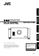
Getting Started DLA-SH7NL INSTRUCTIONS Connection and Installation PROJECTOR Network Settings Operation and Settings (Lens is optional) Thank you for purchasing this JVC product. For Customer use : Enter below the serial No. which is located on the bottom side of the cabinet. Retain this information for future reference. Model No. DLA-SH7NL Serial No. LCT2370-003A Others Please study this instruction manual carefully before starting to operate the unit, in order to use the unit correctly.
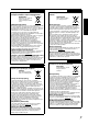
Getting Started Safety Precautions MACHINE NOISE INFORMATION (Germany only) Changes Machine Noise Information Ordinance 3. GSGV, January 18, 1991: The sound pressure level at the operator position is equal or less than 70 dB (A) according to ISO 7779. IMPORTANT INFORMATION This product has a High Intensity Discharge (HID) lamp that contains mercury. Disposal of these materials may be regulated in your community due to environmental considerations.
- Slots and openings in the cabinet are provided for ventilation. These ensure reliable operation of the product and protect it from overheating. These openings must not be blocked or covered. (The openings should never be blocked by placing the product on bed, sofa, rug, or similar surface. It should not be placed in a built-in installation such as a bookcase or rack unless proper ventilation is provided and the manufacturer’s instructions have been adhered to.
Getting Started Safety Precautions (Cont’d) POWER CONNECTION For USA and Canada only Use only the following power cord. Power cord The power supply voltage rating of this product is AC110V – AC240V. Use only the power cord designated by our dealer to ensure Safety and EMC. Ensure that the power cable used for the projector is the correct type for the AC outlet in your country. Consult your product dealer.
EMC Supplement - This equipment is in conformity with the provisions and protection requirements of the corresponding European Directives. This equipment is designed for professional projector appliances and can be used in the following environments. ● Controlled EMC environment (for example purpose built broadcasting or recording studio), and the rural outdoors environment (far away from railways, transmitters, overhead power lines, etc).
Getting Started ENGLISH Information for Users on Disposal of Old Equipment Attention: This symbol is only valid in the European Union. Informations relatives à l’élimination des appareils usagés, à l’intention des utilisateurs Attention: Ce symbole n’est reconnu que dans l’Union européenne. [Union européenne] [European Union] This symbol indicates that the electrical and electronic equipment should not be disposed as general household waste at its end-of-life.
ESPAÑOL / CASTELLANO Información para los usuarios sobre la eliminación de equipos usados PORTUGUÊS Informações para os Utilizadores sobre a Eliminação de Equipamento Antigo Atención: Atenção: Este símbolo sólo es válido en la Unión Europea. Este símbolo apenas é válido na União Europeia. [Unión Europea] [União Europeia] Este símbolo indica que los aparatos eléctricos y electrónicos no deben desecharse junto con la basura doméstica al final de su vida útil.
Getting Started DANSK Brugerinformation om bortskaffelse af gammelt udstyr SVENSKA Information till användare gällande kassering av gammal utrustning Bemærk: Tänk på: Dette symbol er kun gyldigt i EU. Att denna symbol endast gäller inom den Europeiska gemenskapen. [EU] [Europeiska gemenskapen] Elektriske produkter og elektroniske apparater med dette symbol må ikke afhændes på samme måde som almindeligt husholdningsaffald, når det skal smides ud.
РУССКИЙ Информация для пользователей, выбрасывающих старое оборудование Внимание: ČESKY Informace pro uživatele k likvidaci starého zařízení Upozornění: Действие этого символа распространяется только на Европейский Союз. Tento symbol je platný jen v Evropské unii. [Европейский Союз] Это символ указывает, что после окончания срока службы соответствующего электрического или электронного оборудования, нельзя выбрасывать его вместе с обычным бытовым мусором.
Getting Started Contents Getting Started Safety Precautions . . . . . . . . . . . . . . . . . . . . . . . . . . . 2 Contents . . . . . . . . . . . . . . . . . . . . . . . . . . . . . . . . . . 10 Accessories . . . . . . . . . . . . . . . . . . . . . . . . . . . . . . . . 10 Precautions During Use . . . . . . . . . . . . . . . . . . . . . . 11 Names and Functions of Parts . . . . . . . . . . . . . . . . . 12 Connection and Installation Installation . . . . . . . . . . . . . . . . . . . . . . . . . . . . .
Precautions During Use Maintenance Procedures oClean dirt on the cabinet Do this with a soft cloth. In case of heavy soiling, soak a cloth in neutral detergent diluted with water, wring dry and wipe, followed by wiping again using a dry cloth. Burning-in of D-ILA Device oDo not allow the same still picture to be projected for a long time or an abnormally bright video image to be projected Do not project still images with a high brightness or high contrast on the screen for a long time.
Getting Started Names and Functions of Parts Front/Right/Rear Side F G Intake air A CON TRO H Exhaust air Exhaust air L Intake air Intake air B C D E F F A Air Inlet/Filter D Lens Mounting Bracket The air inlets absorb air to cool the interior of the projector. A filter is mounted inside the projector to remove dirt in the air that enters through the inlets. Clean the filter regularly. (A Page 58) Mount the optional projection lens.
Right Side I DVI 1 DVI 2 CONTROL USB DVI 3 LAN OPERATE I/B STANDBY/ON LAMP DVI 4 WARNING RS-232C JKL MNO P Q R I [DVI 1 to 4] Terminal O [LAMP] Indicator This is an input terminal for video signals. Connect it to the video output terminal of the computer. (A Page 21, 23) This indicator lights up in yellow when the lamp time exceeds 1900 hours. J [USB] Terminal Enables control of this projector by connecting it to a computer.
Connection and Installation Installation Please read the following carefully when installing this unit. Optional Projection Lens Mount the optional projection lens (A Page 60). For details on mounting the lens, please consult your authorized dealer. Minimum Space Required Do not use a cover that may enclose this unit or block the air inlets/vent holes. Allow sufficient space around this unit.
Projector Installation Angle You can install this projector between 90 . Images will be properly displayed if the horizontal angle is between the range of 5 . However, you have to configure using [Installation Style](A Page 48) for certain installation orientations.
Connection and Installation Installing the Projector and Screen (Cont’d) Movable Range of Projected Image GL-MS4015SZG Zoom lens Projected Image 50 % When shift amount in the right direction is +25 % 25 % 25 % Install the projector such that the center of the lens is aligned with the 1/4 position from the left edge of the screen.
Overlaying projected images (when zoom lens is in use) Projecting images by stacking projectors When light passes through the glass of projection booth The lens shift feature enables you to use up to three stacked projectors at the same time. Stacking the projectors enhances the brightness level, and helps to project images that are sufficiently bright even when the venue is relatively big or bright.
Connection and Installation Installing the Projector and Screen (Cont’d) Screen Size and Projection Distance Adjust the distance from the lens to the screen to achieve your desired screen size. GL-MS4015SZG Zoom lens Projection distance Projection Screen Size (Diagonal Length) Image Width Tele End Wide End 80" (Approx. 2.03 m) 1.75 m 3.19 m 2.58 m 90" (Approx. 2.29 m) 1.97 m 3.60 m 2.91 m 100" (Approx. 2.54 m) 2.19 m 4.01 m 3.25 m 110" (Approx. 2.79 m) 2.41 m 4.42 m 3.
GL-MS4011SG Short focal length lens Projection Screen Size (Diagonal Length) Image Width Projection distance 50" (Approx. 1.27 m) 1.10 m 1.16 m 60" (Approx. 1.52 m) 1.31 m 1.41 m 70" (Approx. 1.78 m) 1.53 m 1.66 m 80" (Approx. 2.03 m) 1.75 m 1.91 m 90" (Approx. 2.29 m) 1.97 m 2.16 m 100" (Approx. 2.54 m) 2.19 m 2.41 m 110" (Approx. 2.79 m) 2.41 m 2.66 m 120" (Approx. 3.05 m) 2.63 m 2.91 m 130" (Approx. 3.30 m) 2.85 m 3.17 m 140" (Approx. 3.56 m) 3.07 m 3.42 m 150" (Approx.
Connection and Installation Connecting Video Signals of the Computer Connection During Single-Screen Mode Display The single-screen mode displays signals (up to four signals) from a computer as a single video image. To select to the single-screen mode, set ADisplay ModeB in the Setting menu to ASingleB.
Normal 2 Stripes DVI 1 DVI 1 DVI 3 4 Stripes DVI 1 DVI 2 Cross DVI 3 DVI 4 DVI 1 DVI 2 DVI 3 DVI 4 Connection During Single-Screen Mode Display Below is the connection example for four-channel signals from the computer. For two-channel signals from the computer, connect to the [DVI 1] and [DVI 3] terminals of this projector.
Connection and Installation Connecting Video Signals of the Computer (Cont’d) Connection During Two-Screen/ Four-Screen Mode Display The two-screen/four-screen mode enables simultaneous display of signals from two or four computers. To select the two-screen mode, set ADisplay ModeB in the Setting menu to ADoubleB. To select the four-screen mode, set ADisplay ModeB to ACrossB.
Connection Example During Two-Screen Mode Desktop Computer To DVI Terminal DVI 1 DVI-D Cable (Sold Separately) DVI 2 Laptop Computer CONTROL USB DVI 3 LAN OPERATE I/B STANDBY/ON LAMP DVI 4 WARNING RS-232C To DVI Terminal Connection Example During Four-Screen Mode Desktop Computer To DVI Terminal DVI-D Cable (Sold Separately) To DVI Terminal DVI 1 DVI 2 Laptop Computer CONTROL USB DVI 3 LAN OPERATE I/B STANDBY/ON LAMP DVI 4 WARNING RS-232C To DVI Terminal To DVI Terminal NOTE: ● Dependin
Network Settings Connection Using a LAN Cable Connect this projector, the computer for controlling this projector, and the switching hub using LAN cables, followed by configuring the network. When assigning a static IP address You can acquire the IP address from the controlling computer simply by configuring a network that consists of this projector, the controlling computer, and switching hub. Please refer to technical books on networks for details.
Turning On the Main Power 1 Check to ensure that this projector, computer, and switching hub are properly connected 2 Connect the power cord to the power input terminal of this projector 5 CAUTION: 2 Power Cord (Supplied) 3 ● Do not connect the power cord when a lens (optional) is not attached. You can secure the power cord to this projector. A Attach the plug holder to the power cord. B Insert the plug holder into the projector until the upper and lower securing levers are locked.
Network Settings IP Address Settings Set the IP address for this projector. There are 2 methods to set the IP address. Assigning a static IP address Assigning an IP address from the DHCP Server Assigning a static IP address The AIP Address SettingB of this projector is set to ASTATIC IPB (the DHCP client function is OFF) by default. Upon turning on the power, this projector starts running with the following IP address. IP Address Subnet Mask Default Gateway : 192.168.0.2 : 255.255.255.0 : 192.168.
Setting (Changing) the IP address of this projector 1 Launch the Internet Explorer on the computer 2 Check if the proxy has been set in the ALAN SettingB of the Internet Explorer A Click AToolsB and select AInternet OptionsB B Click AConnectionsB and click ALAN SettingB C Check if the check for AUse a proxy server for your LANB has been selected ● If the check mark has been selected, deselect it.
Network Settings 7 Click AAdmin.NetworkB in the main menu IP Address Settings (Cont’d) host PJ-1 user: advanced Logout Main Image Setting Assign Power Warning Status ON OFF PROJECTION None Lamp Mode Convergence Assigning a static IP address (Cont’d) Lens Option Admin.Network Admin.E-Mail 4 Enter Ahttp://192.168.0.2B in the address field of the Internet Explorer, and click AGoB Admin.Option Admin.Signal ● A login screen for this projector appears.
Assigning IP Address from the DHCP Server Using the Mail Delivery Feature The IP address is automatically assigned by the DHCP server. 1 After connecting, turn on the main power ● Refer to Page 24 on the details of connection. ● Refer to Page 25 on procedures to turn on the main power. 2 Set the ADHCP ClientB setting of this projector to ADHCPB ● The ADHCP ClientB of this projector is set to ASTATIC IPB (the DHCP client function is OFF) by default.
Operation and Settings 3 Adjust the zoom ratio (screen size) (when Projecting Image zoom lens is in use) You can adjust the focus using the AZoomB item of the Lens menu. host PJ-1 user: root If setting for this projector is not completed, refer to AUser Settings MenuB(A Page 33) upon turning on the power and configure the settings accordingly. Once the basic settings are configured, this projector can be used by simply performing the following operation procedures.
5 Adjust the focus 8 Turn the main power at the rear of the You can adjust the focus using the AFocusB item of the Lens menu. To move the focus point closer: Press the A+B (Near) end of AFocusB B (Far) end of AFocusB NOTE: ● The focus changes each time you click on the inner buttons ( / ). (Fine control) The outer buttons ( / ) change the focus when they are depressed. (Coarse control) 6 Select a screen mode for projection You can specify the screen mode using ADisplay ModeB of the Setting menu.
Operation and Settings 3 Click ALOGINB Displaying the Menu ● The main menu for this projector appears. NOTE: 1 Enter the IP address assigned in the address field of the Internet Explorer, and click AGoB (A Page 28) ● Example: When IP address assigned is A192.168.0.2B, enter Ahttp://192.168.0.2B. http://192.168.0.2 1 NOTE: ● When ALAN SettingB in Internet Explorer is set to AUse a proxy server for your LANB it may not be possible to designate addresses directly. Change the proxy settings.
User Settings Menu After installation and connection are complete, perform the necessary adjustment and setting. Operate the menus using the computer’s browser to make adjustments and configure settings.
Operation and Settings User Settings Menu (Cont’d) (1) Main Menu This menu displays the ON/OFF status of the power supply and information on signals input to the projector. host PJ-1 user: root Logout Main Image Setting Power ON Warning Status OFF PROJECTION None Lamp Mode Convergence Lens Option Both Lamp1 Lamp2 Auto Lamp Information Hide Lamp 1 Status ok Time 10h54m 2 ok 11h58m OFF Signal Status ON Temperature DVI Rate(Hz) Pixel H Pixel V Link 1 60.00 2048 2400 Dual 60.
indicates the factory default. Item Power Setting Value ON OFF Description For turning on/off the lamp selected in ALamp ModeB. ON : Turns on the lamp. OFF : Turns off the lamp. NOTE: ● The following operating modes of the projector are displayed to the right of the OFF button.
Operation and Settings User Settings Menu (Cont’d) (1) Main Menu (Cont’d) indicates the factory default. Item Signal Status DVI Rate(Hz) Pixel H Pixel V Link Setting Value ^ ^ ^ ^ ^ Description Displays information on the input signals. DVI : Displays the DVI input terminal number. Rate(Hz) : Displays the vertical frequency. Pixel H : Displays the horizontal resolution. Pixel V : Displays the vertical resolution. Link : Displays the link status of the DVI terminal.
(2) Image Menu This menu is used for adjusting the picture quality. host PJ-1 user: root Logout Main Brightness Image Setting Red -30 Green -30 Blue -30 Red -30 Green -30 Blue -30 0 0 Convergence Lens 0 +30 +30 +30 Option Contrast 0 0 0 Gamma A +30 +30 +30 Hide B C OFF ON indicates the factory default. Item Brightness Red Setting Value For adjusting the brightness of the red, green, and blue colors.
Operation and Settings User Settings Menu (Cont’d) (3) Setting Menu This menu is used for specifying the input level of the terminal and the display mode. host PJ-1 user: root Logout Main Input Level Image 0-255(PC) Setting Display Mode 16-235 Convergence 1 1 3 Lens 1 2 3 4 Option Single Double Cross indicates the factory default. Item Input Level Setting Value Q 0-255(PC) 16-235 Description For specifying the input level of the video signals.
(4) Convergence Menu This menu is used for correcting color shifts in the optical system. host PJ-1 user: root Logout Main Red Blue U Image U Setting Convergence Lens L R L R Option D D Test Pattern OFF OFF SET indicates the factory default. Item Setting Value Description Red ^ For adjusting the horizontal/vertical position of red and blue colors on the image. Blue ^ NOTE: ● The green color value is fixed.
Operation and Settings User Settings Menu (Cont’d) (5) Lens Menu This menu is used for adjusting the projection lens. host PJ-1 user: root Logout Zoom Main Image Focus w Shift U + Setting Convergence Lens L R _ Option T D Test Pattern OFF Item Zoom OFF Setting Value ^ SET Description For adjusting the zoom ratio (screen size). NOTE: ● The zoom position changes each time the inner button is clicked. The zoom position changes when the outer button is depressed.
(6) Option Menu This menu is used for specifying settings for the method of screen display, lamp brightness and others. host PJ-1 user: root Logout Main Flip Horz. Image ON OFF Vert. ON OFF Setting Convergence Lamp Power High Lens Option Back Color Low Blue Black Message Display ON OFF Test Pattern OFF OFF SET indicates the factory default. Item Flip Horz. Vert.
Memo : 42
Administrator Settings Menu After installation and connection are complete, perform the necessary adjustment and setting. Operate the menus using the computer’s browser to make adjustments and configure settings. Administrator Settings Menu Structure For details on page menu (1) to (6), refer to AUser Settings MenuB (A Page 33 to 41).
Operation and Settings Administrator Settings Menu (Cont’d) (7) Admin.Network Menu For configuring the network settings. host PJ-1 user: advanced Logout Host Name Setting Main Host Name Image PJ ZZZZZZ SET Setting Convergence IP Address Setting DHCP Client Lens Option Admin.Network Admin.Mail DHCP STATIC IP IP Address 192.168.1.100 Subnet Mask 255.255.255.0 Default Gateway 192.168.1.1 Admin.Option Admin.
Item User Login Name/ Password Change User Name New Password Confirm New Password Initialize Setting Value Description For changing the login name and password. User Name : For changing the login name. root ^ ^ New Password : For changing the login password. Confirm New Password : Re-enter the new password. (For confirmation) ^ Initialize : For resetting the username/password. NOTE: ● You can change it to a random name.
Operation and Settings Administrator Settings Menu (Cont’d) (8) Admin.E-mail Menu This menu is for configuring the mail settings, which sends out an error message to the computer of the preset address when an abnormality occurs within this projector. host PJ-1 user: advanced Logout Main Image Setting E-Mail Setting E-Mail ON OFF E-Mail Sender user@localhost E-Mail Address user@localhost Convergence Lens Option Admin.Network Admin.E-Mail SMTP Server Address 1.1.1.1 E-Mail Auth. ON Auth.
indicates the factory default. Item Setting Value E-Mail Setting E-Mail Description For configuring the e-mail feature. ON Q OFF ON : Use the mail feature. OFF : Do not use the mail feature. E-Mail Sender ^ (Default Value: lower 3 bytes of the MAC address) For specifying the destination e-mail address of this projector. E-Mail Address ^ (Default Value: user@localhost) For specifying the destination e-mail address. ^ (Default Value: 1.1.1.
Operation and Settings Administrator Settings Menu (Cont’d) (9) Admin.Option Menu This menu is used for specifying settings including image and option, and for resetting the lamp. host PJ-1 user: advanced Logout Main Color Depth Setting Frame Lock 8bit Image 12bit ON Mech. Shutter OFF High Altitude Convergence ON Lens Option OFF ON OFF Installation Style Admin.Network A B C Admin.E-Mail Admin.Option Admin.
(10) Admin.Signal Menu This menu is for configuring settings such as display format, and for rewriting EDID. host PJ-1 user: advanced Logout Force Signal Main OFF Image Setting SET OFF Convergence Signal Status Lens DVI Rate(Hz) Pixel H Pixel V Link Option 1 60.00 2048 2400 Dual Admin.Network 2 60.00 2048 2400 Dual Admin.E-Mail 3 Admin.Option 4 Admin.Signal Display Mode 1 1 3 1 2 3 4 EDID Browse Single Double SET Cross indicates the factory default.
Operation and Settings Administrator Settings Menu (Cont’d) (10) Admin.Signal Menu (Cont’d) indicates the factory default. Item Signal Status DVI Rate(Hz) Pixel H Pixel V Link Setting Value ^ ^ ^ ^ ^ Description Displays information on the input signals. Same as ASignal StatusB in the User Menu. DVI : Displays the DVI input terminal number. Rate(Hz) : Displays the vertical frequency. Pixel H : Displays the horizontal resolution. Pixel V : Displays the vertical resolution.
Others Troubleshooting Check the following points before sending this product for repair. The following phenomena are not malfunctions. If there is no abnormality on the screen when the phenomena below appear, they are not malfunctions.
Others Troubleshooting (Cont’d) Symptom Probable Cause Corrective Action Reference Page ● Is the projector out of focus? ● Adjust the focus using AFocusB of the Lens menu. A Page 31, 40 ● Is the projection distance too short or too long? ● Set it to a correct distance. A Page 18, 19 Image is unusually dark or bright ● Is the brightness level properly adjusted? ● Adjust accordingly using ABrightnessB of the Image menu. ● Adjust ALamp PowerB in the Option menu.
What to do when these messages are displayed Messages are displayed when the lamp life has expired and when there is input of signals that cannot be used. Message Lamp Time Over Message Lamp Time Over Out of Range No Input Cause (Details) ● Displayed when the lamp time has exceeded 2000 hours. The message is displayed for a period of 3 minutes during each projection. Replace with a new lamp unit. For details on replacement of the lamp unit, please consult your authorized dealer.
Others Warnings Using Indicators The lamp time and warning mode are indicated using the indicator. For indicator displays during normal operation, refer to the note below. Indicator No. STANDBY/ ON LAMP Description WARNING About time to replace lamp (Lamp time has exceeded 1900 hours.) 1 *1 Light On (Yellow) - *2 Blinking (Yellow) Light On (Red) 2 3 4 When the lamp life has expired (Lamp time has exceeded 2000 hours. Message displayed.
Warning Status The latest error code (Warning Status) appears in the Main Menu when an abnormality occurs in the projector. Error details are as follows: Error Code 1 2 6 8 9 A 15 30 31 32 33 40 41 42 43 44 45 46 47 48 49 4A 50 51 52 56 Meaning Lamp 1 does not turn on. Accumulated lamp time for Lamp 1 has exceeded 2000 hours. Lamp 1 goes off during projection. Abnormally high temperature in the projector. Abnormally high temperature around the intake vent.
Others RS-232C Interface You can control this projector via a computer by connecting the computer to this unit using a RS-232C cross cable (D-sub 9 pins). The commands to control this unit and the response data format against the received commands are explained here. For details, please consult your authorized dealer.
Parameters used for the data format The following 2 types of parameters are used for command and response data: (1) ON/OFF (2) Special Parameter Each parameter is as follows: (1) ON/OFF Shows the status (ON or OFF) of the unit, such as POWER and HIDE.
Others Maintenance Turn off the power of the projector unit, and unplug the power cord when cleaning or replacing the filter. Cleaning and Replacing the Filter Clean the filter regularly. If the filter is soiled, air intake efficiency may deteriorate, thus resulting in malfunction of the product. Replace with a new one if the filter fails to remove dust thoroughly or if it is damaged. Failure to do so may cause dust to enter the projector and shadows to appear on the projected image.
1 Remove the filter cover The filter is located at the front side of the projector unit. 2 Remove the sponge and filter Hold the center of the filter using your fingers, and pull the filter toward you to remove it. 3 Clean the sponge and filter Remove any dirt or dust using a vacuum cleaner. CAUTION: ● Do not clean using a flammable air duster. This may cause fire. 4 Mount the sponge and filter Mount the filter and sponge to the projector using the reverse removed procedure.
Others Specifications General Optional Items Power supply Projection lens AC 110 V to AC 240 V 50 Hz/60 Hz Power consumption 1100 W (Standby mode: 6 W) Current consumption Max 9.5 A Calorific power 3960 kJ/h (946 kcal/h) Air capacity Intake: Approx. 3 m3/min Exhaust: Approx.
Pin Arrangement RS-232C Terminal 5 9 6 1 Pin No. 2 3 5 1, 4, 6-9 Signal RxD TxD GND NC Action Incoming Data Outgoing Data Signal Ground ^ Signal Direction This Projector PC This Projector PC ^ ^ DVI-D Terminal 8 7 6 5 4 3 2 1 16 15 14 13 12 11 10 9 24 23 22 21 20 19 18 17 Pin No.
Others Specifications (Cont’d) Dimensional Outline Drawing (Unit: mm) 35 59.5 Side 30 Top 677 DVI 1 199 DVI 2 CONTROL USB DVI 3 LAN OPERATE I/B STANDBY/ON LAMP DVI 4 WARNING M10 hole (x 12) Tightening depth: 10 to 20 59.5 783 688 RS-232C (Projection lens 127 is optional) 660 30 Front Rear 494 660 26 to 46 330 342 to 362 Center of lens 181 133 156 43.
Memo : 63
DLA-SH7NL PROJECTOR © 2010 Victor Company of Japan, Limited Printed in Japan 0210TTH-SW-VP