
Digital Video Printer Instructions Manual

8 EN
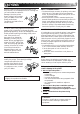
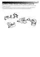
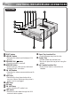
CONTROLS, INDICATORS AND CONNECTORS
Front View
1
PRINT button
2
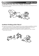
IrDA/DV button
•Switches the video input between IrDA
and DV.
3
STANDBY/ON button
•Turns the printer on and off.
4
MEMORY button
•Used to store a video picture delivered
through the DV connector.
5
ON LINE button
•Press this for video communications with
your PC.
6
Vent holes
•Periodically clean these holes with a
vacuum cleaner. Make sure the printer’s
power cord is unplugged.
7
IrDA lamp
8
DV lamp
9
ON LINE lamp
•Lights when the PC mode is on.
0
IrDA sensor
•Receives a video data through the IrDA
communication system.
!
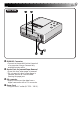
Paper Tray Insertion Slot
•Insert the paper tray into this slot.
@
Output Tray
•Printed sheets are stacked here.
* Be sure to open the tray when using the
printer.
#
Ink Cassette Insertion Slot
•Open this to load or unload the ink
cassette.
1 2345 6
7
8
9
0
!@#