GV-DS1 JLIP VIDEO CAPTURE DOCKING STATION ENGLISH BASE DE MONTAGE A CAPTURE VIDEO JLIP FRANÇAIS GV-DS1 JVC COMPANY OF AMERICA DIVISION OF US JVC CORP. 41 Slater Drive, Elmwood Park, N.J. 07407 JVC CANADA INC. 21 Finchdene Square, Scarborough Ontario M1X 1A7 INSTRUCTIONS MODE D'EMPLOI For Customer Use: Enter below the Serial No. of the GV-DS1U JLIP VIDEO CAPTURE DOCKING STATION. The serial number is located on the bottom of the JLIP VIDEO CAPTURE DOCKING STATION. Model No. GV-DS1U Serial No.
Dear Customer, Thank you for purchasing this VIDEO CAPTURE DOCKING STATION. Before use, please read the safety information and precautions contained in the following pages to ensure safe use of this product. Using This Instruction Manual • All major sections and subsections are listed in the Table Of Contents (Z pg. 8, 9). • Notes appear after most subsections. Be sure to read these as well. • Basic and advanced features/operation are separated for easier reference. It is recommended that you . . . ....
IMPORTANT PRODUCT SAFETY INSTRUCTIONS Electrical energy can perform many useful functions. But improper use can result in potential electrical shock or fire hazards. This product has been engineered and manufactured to assure your personal safety. In order not to defeat the built-in safeguards, observe the following basic rules for its installation, use and servicing. ATTENTION: Follow and obey all warnings and instructions marked on your product and its operating instructions.
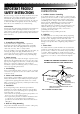
USE SERVICING 1. Accessories 1. Servicing To avoid personal injury: • Do not place this product on an unstable cart, stand, tripod, bracket or table. It may fall, causing serious injury to a child or adult, and serious damage to the product. • Use only with a cart, stand, tripod, bracket, or table recommended by the manufacturer or sold with the product. • Use a mounting accessory recommended by the manufacturer and follow the manufacturer’s instructions for any mounting of the product.
CAUTIONS If you notice smoke or a peculiar smell coming from the VIDEO CAPTURE DOCKING STATION unplug it IMMEDIATELY. Use of the VIDEO CAPTURE DOCKING STATION under these conditions could lead to fire or electric shock. Contact your JVC dealer. DO NOT attempt to repair the malfunction yourself. DO NOT attempt to insert foreign objects into the connectors, as this can lead to electric shock or fire. If an object is accidentally inserted, unplug it and contact your JVC dealer.
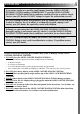
CAUTIONS (cont.) How to handle a CD-ROM ● Take care not to soil or scratch the mirror surface (opposite to the printed surface). Do not write anything or put a sticker on either the front or back surface. If the CD-ROM gets dirty, gently wipe it with a soft cloth outward from the center hole using a circular motion. ● Do not use conventional disc cleaners or cleaning spray. ● Do not bend the CD-ROM or touch its mirror surface. ● Do not store your CD-ROM in a dusty, hot or humid environment.
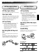
MAJOR FEATURES Two software programs are provided with the GV-DS1 JLIP package. JLIP Video Capture Software JLIP Player Software (Z pg. 12 – 39) (Z pg. 41 – 65) JLIP Video Capture Software JLIP Control Facility This is the software described in this manual.
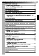
CONTENTS MAJOR FEATURES 7 ADVANCED APPLICATIONS 10 CONTROLS AND CONNECTORS 11 CONNECTIONS (When Using JLIP Video Capture Software) 12 INTRODUCTION 14 INSTALLATION (JLIP Video Capture Software) 15 HOW TO OPEN THE PROGRAM 16 Preparation ................................................................... 16 INITIALIZATION 17 Initializing JLIP .............................................................. 17 Select units ....................................................................
JLIP PLAYER SOFTWARE 34 Using JLIP player software data ........................................... 34 How to store JLIP player software data ................................. 35 TROUBLESHOOTING 36 LIST OF ERROR MESSAGES 38 JLIP PLAYER SOFTWARE SECTION 41 CONNECTIONS (When Using JLIP Player Software) 42 When connecting to a video source unit with JLIP connector or to a video printer ................................................................
Create title indexes for your video collection Title index images can be captured from your favorite recordings in intervals of 30 minutes, 1 hour, 1.5 hours, etc. using the Interval Capture mode. Print the captured index images on your PC printer using the computer's Print Screen facility, then attach them to your cassettes. Business presentations Images captured from video can be incorporated into business documents to spice up your presentations.
CONTROLS AND CONNECTORS The controls and connectors marked * can be used only when the GR-DVM1 Digital Camcorder is attached. For details of its operation, read the camcorder instruction manual. * Stop button * Play button * Rewind button * Fast forward button * Pause button * Edit start button * Lock lever * Unlock button * Digital jack Z p. 13 • Connect to the computer’s RS-232C terminal (COM port). * MULTI connector • The Docking Station can be connected with the GR-DVM1 through this connector.
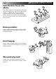
CONNECTIONS n To assure safety, make sure all units are turned off before making any connections. n The video images will be displayed on the LCD screen of the attached GR-DVM1. You cannot view the images on the computer screen. n When connecting the provided cables, be sure to connect the terminals equipped with Core filters to the Video Capture Docking Station. n When using the Video Capture Docking Station, use the AA-V80U AC Adapter/Charger (optional or provided with the camcorder).
Digital Camcorder AC Adapter/Charger Video Capture Docking Station To DC output jack JLIP DC cable (provided) Core filter To JLIP jack Core filter (red) (white) (yellow) 3.5 mm dia. 4-pole cables (provided) Core filter Other units with video output jack AUDIO/VIDEO cable (provided) To CAPTURE INPUT (EXT.
INTRODUCTION What is video capture software ? Video capture software is a type of application program that allows you to capture video images from camcorders and VCRs and store them in personal computers running under the WindowsT operating system. These images can be transferred from the video source to the computer via a standard RS-232C communication interface.
INSTALLATION (JLIP Video Capture Software) 15 WINDOWST 95 WINDOWST 3.1 Refer to the WindowsT 95 manual or your computer’s manual for details on basic WindowsT 95 operating procedures. Refer to the WindowsT 3.1 manual of or your computer manual for details on basic WindowsT 3.1 operating procedures. Installation Procedure Installation Procedure *To start the setup program... *To start the setup program... WindowsT 95 1 Launch •Close any other applications that are WindowsT 3.
HOW TO OPEN THE PROGRAM The Video Capture software can be started up in the same way as any other program running under Windows. The procedure differs slightly depending on whether you’re using WindowsT 3.1 or WindowsT 95. Preparation • • • • • Turn on your computer. Press the POWER button to turn on the power. Turn on the video source units (such as camcorders and VCRs). If you want to capture a still picture from a recorded tape, load the tape into the video unit.
INITIALIZATION INITIALIZING JLIP The first time you start the Video Capture software, JLIP initialization is required. This sets which of the computer’s COM ports (connector into which the RS-232C cable is plugged) is connected to the GV-CB1 JLIP Video Capture Docking Station. The initialization window automatically appears the first time you start the software after installation. Do not forget to carry out this JLIP initialization procedure.
INITIALIZATION SELECT UNITS 6. 7. The "Device Selection" window appears, listing the JLIP devices. Click the name of the desired unit. •The word "VCRCAMERA" appears in the VCR box to indicate the Video source unit is now in use. •The word "MODULE" appears in the Video Capture box to indicate the Video Capture Docking Station is now in use. •Only one VCR and one Video Capture device can be selected. 8. Click "OK". •The main desktop window returns (setting complete).
HOW TO CLOSE THE PROGRAM Double-click the control menu button in WindowsT 3.1 or click "Exit" in the "File" menu. In WindowsT 95, simply click the Close button. If you try to close the program with no image saved, the message "The album has not been saved. Save?" appears. Please note that if you close without saving, all unsaved captured data will be deleted. "Exit" from "File" in the menu bar. 1 Click •The program closes.
HOW THE DESKTOP WORKS MAIN DESKTOP WINDOW 1. Menu bar 2. Control 3. Image display area buttons Close button JLIP Video Capture [–Untitled Folder–] (Untitled) File Edit Set-up Window Help CAPTURE TRANSFER MEMORY INPUT JLIP 01 02 03 04 05 00:01:23:12 00:02:17:21 00:07:01:19 00:37:05:06 00:20:39:18 06 07 08 00:39:03:11 00:47:53:03 --:--:--:-- bar 1 Menu Displays function menus. See the next page for detailed information.
display area 3 Image Each time you press the Capture button an image is captured by this device. An index image is transferred to the computer and displayed in the image area. Up to 99 images can be captured, with up to five images per line. Index images are provided to allow you to confirm that you have captured the images you want.
HOW THE DESKTOP WORKS (cont.) Each pulldown menu is configured as follows File New Album Open Album Save Album Ctrl+S Open JLIP (jlp) File Save As JLIP (jlp) File Save Image As… Ctrl+A Edit Transfer the Index Image Transfer the Full Image Modify… Delete Del Capture Mode Image Format Device Change Initialize ID Change Counter Reset Saves the image file to another folder or drive (Z p. 33). Closes the program ( Z p. 19). Exit Set-up Erases the current album and creates a new album.
Window Arrange Index VCR Arrange the index image after an index image has been deleted (Z p. 31). The VCR operation window appears to allow the computer to control the VCR.
VIDEO CAPTURE CAPTURING VIDEO IMAGES There are three capture modes available: Step by Step, Program and Interval. The latter two modes are available only when connected to a JLIP compatible video source unit. Step by Step Capture mode must be used to capture images from a video source unit with no JLIP connector. Image data flow Video source unit Video signal GV-DS1 (Image stored in video memory) Full image (with a resolution of 640 x 480 pixels) 2 types of full size images • Bitmap format Approx.
STEP BY STEP CAPTURE Use the Step by Step Capture mode when you want to: •Capture images from a video source unit with no JLIP connector •Capture images from video units with video output connectors •Capture a small number of images •Confirm the images being captured. Preparation Set-up Capture Mode Image Format Device Change Initialize ID Change Counter Reset Step by Step Automatic •Make sure all units are properly connected (Z p. 12).
VIDEO CAPTURE (cont.) AUTOMATIC CAPTURE Automatic video capture is available only when a JLIP-compatible video source unit is connected. There are two types of automatic capture: Program mode and Interval mode. You can save time in either mode because, once the initial settings have been stored or you have decided what pictures to capture, the subsequent capture process is carried out automatically.
the menu bar, click "Window" — 4 On "VCR" to call up the VCR Operation window. VCR I 00:01:23:12F Capture the video source unit via the 5 Operate VCR Operation window and click the "Capture" button to capture the desired video image. Transfer Click the "Capture" button on the desired 6 video image, and index image (80 x 60 pixels) is transferred to the computer. •The message "No.1 index image being transferred" appears during data transmission. 7 Repeat steps 5 and 6 as necessary.
VIDEO CAPTURE (cont.) Preparation INTERVAL CAPTURE The Interval Capture mode is best suited for capturing images at set intervals from a video source unit with a JLIP connector. Set-up Capture Mode Image Format Device Change Initialize ID Change Counter Reset 1 At the menu bar, click "Set-up" — "Capture Mode" — "Automatic". •The "Automatic Transfer" window appears. 2 Select the data to be transferred.
PICTURE FORMAT SETTING SELECTING A PICTURE FORMAT Under "Image Format", you can specify the full image format and the capture mode. menu bar, 1 "Atclickthe"Set-up" — ". Image Format •The "Image Format" window appears. Set-up Capture Mode Image Format Device Change Initialize ID Change Counter Reset format. 2 Select •There are two different settings avail- able: "JPEG (9. jpg)" and "Bitmap (9. bmp)". Refer to "Picture Data Format" below for details. capture mode.
ADDITIONAL OPERATIONS COUNTER VALUE CHANGE If you want to replace a captured image with a different one, you can capture the new one by changing the counter value. 02 the image display box of the index 1 Click number you want to change. •The box is bordered in green. 00:02:17:21 the menu bar and click "Edit" — 2 Open "Modify…". •The "Modify Capture Point" window appears. Edit Transfer the Index Image Transfer the Full Image Modify… Delete Del a new counter value. 3 Enter "OK".
DELETE INDEX IMAGE AND FULL IMAGE You can delete any captured picture. Both index image (80 x 60 pixels) and full image (640 x 480 pixels) are deleted. 02 the image display box you want to 1 Click delete. •The box is bordered in green. 00:02:17:21 the menu bar and click "Edit" — 2 Open "Delete". •This deletes the selected image data. Edit Transfer the Index Image Transfer the Full Image Modify… Delete Del click "Window" — "Arrange 3 Then Index".
SAVE PICTURE CREATE NEW FOLDER Creating a new folder (directory) is a good idea when capturing an image from another video tape. File New Album Open Album Save Album Ctrl+S Open JLIP (jlp) File Save As JLIP (jlp) File Save Image As… the menu bar and click "File" — 1 Open "New Album". •The image display area is refreshed. •If the index image data on screen is not saved, you will be asked whether to save or not.
OPEN INDEX File New Album Open Album Save Album Ctrl+S Open JLIP (jlp) File Save As JLIP (jlp) File Save Image As… Ctrl+A Exit the menu bar and click "File" — 1 Open "Open Album". •The "Open Album" window appears. 2 Select the name of the folder (directory). 3 Click "OK". SAVE THE FULL IMAGE DATA You can save a file under another name or in another folder so that you can edit it without losing the original.
JLIP PLAYER SOFTWARE USING JLIP PLAYER SOFTWARE DATA The GV-DS1 Video Capture Docking Station can capture JLIP Player software data at an edit-in point corresponding to a preset counter number. Preparation •Make sure all units are properly connected (Z p. 12). •Insert the tape program edited with the Player Software into the video source unit. •If the data is stored on a floppy disk, load disk into the floppy disk drive.
HOW TO STORE JLIP PLAYER DATA Data from this unit can be converted to JLIP Player software files. If index image data is saved as a JLIP Player software file, the file can be printed with the optional GV-PT1/GV-PT2 Video Printer. Refer to the instruction manual for details. Preparation •Make sure all units are properly connected (Z p. 12). •Insert a video tape into the video source unit.
TROUBLESHOOTING NOTE : External noise or disturbance may interfere with the microprocessors built into the GV-DS1 JLIP Video Capture Docking Station. If this happens, turn the power off and then turn it on again. Problem Cause Page No effect when clicking the Input Select/Memory buttons. v The windows do not change during transfer or compression of index image/full image data. v The video is displayed on the LCD screen of the attached GR-DVM1.
TROUBLESHOOTING (cont.) 37 Problem Cause Page Cannot capture video data with the desired counter number. v There may be a slight difference between the counter of the video image that you want to capture and the Index image data/ Full image data captured in the computer. This is not a malfunction. 25 – 28 Counter cannot be reset. v Counter reset is not available with digital camcorders. 30 Program capture suddenly stops.
LIST OF ERROR MESSAGES Message v Appears when: m Action: COM port is not available. v Not connected to COM port set by JLIP Initialize. m Check the COM port number and connector and retry JLIP initialization. 18 Connected device not found. v Connected devices are not turned on. v Selected COM port is not connected properly. m Make sure connection is proper and carry out JLIP initialization. Then turn on this unit and the connected devices. 18,19 Battery depleted.
Message v Appears when: m Action: Execute after playing back the VCR. v Video unit is not in Play mode during Interval Capture. m Click "OK", set the video unit to Play and click "Transfer" again. 28 Not enough disk space is available. v Remaining disk space is under 1 MB. m Click "OK" , check disk space and select a drive with space available with Store As. — Communication error. v If operation stops after this message appears, turn the Capture Docking Station off and then on again.
MEMO
JLIP PLAYER SOFTWARE SECTION q The Readme.TXT file provides additional information for setup and information that is not included in the instruction manual. Please read the file before installing the provided software program. q You can find the latest information (in English) on the provided software program at our world wide web server at http://www.jvc-victor.co.
CONNECTIONS (When Using JLIP Player Software) WHEN CONNECTING TO A VIDEO SOURCE UNIT WITH JLIP CONNECTOR OR TO A VIDEO PRINTER n Be sure to turn off the power of all connected units before making any connections. n When connecting the provided cable, be sure to connect the plug with the Core Filter to the Video Capture Docking Station. To digital connector (8 pin) To COM port (RS-232C) Core Filter PC connection cable (provided) PC 3.
n When using the Video Capture Docking Station, use the AA-V80U AC Adapter/Charger (optional or provided with the camcorder). Digital camcorder JLIP JLIP Video Capture Docking station To edit jack To JLIP jack Core Filter AC Power Adapter/Charger Connect this if the video unit has a JLIP connector To DC output jack DC cord To S (yellow) (white) (red) output To video/ jack audio output jack Core Filter Core Filter Connect this if the video unit has an S input jack 3.
GETTING STARTED What is JLIP ? JLIP* stands for Joint Level Interface Protocol, a new communication protocol which allows AV units equipped with a JLIP terminal to be controlled by a personal computer. * is a registered trademark of JVC. Operating Environment ● Personal computer with MicrosoftT WindowsT 3.
INSTALLING (JLIP Player Software) 45 WINDOWST 95 WINDOWST 3.1 Refer to the WindowsT 95 manual or your computer’s manual for details on basic WindowsT 95 operating procedures. Refer to the WindowsT 3.1 manual of or your computer manual for details on basic WindowsT 3.1 operating procedures. Installation Procedure Installation Procedure *To start the setup program... *To start the setup program... WindowsT 95 1 Launch •Close any other applications that are WindowsT 3.
STARTING JLIP PLAYER SOFTWARE Starting JLIP Player Software DEVICE(S) 1 PREPARE Turn the device(s) on and set the camcorder's Power Dial to "PLAY". MOVIE PLAYER 2 ACCESS Double-click the MOVIE PLAYER icon MOVIE PLAYER and the Serial Port Selection dialog box appears. SERIAL PORT 3 SELECT Select the port number of the connector you are using to connect the computer to the Video Capture Docking Station. •If the connector number is A, B... A corresponds to 1.
•An error message "No devices detected to connect. Power ON all devices in system." appears . . . ... when a wrong port number is selected. ... when the connection is wrong. ... when the device's ID number is already in use. ... when the device's power is not turned on. Check the Serial Port selection, too. To return to step 1, check the connection and the device's power and try again. Device Selection Select device to control.
MOVIE PLAYER WINDOW BUTTONS AND DISPLAYS 5. POWER button Control-menu box Menu bar 1. COUNTER system 3. ID number 2. Tape counter display Title bar Minimize button MOVIE PLAYER File Edit Video Printer 4. FILE name Help COUNTER Non Drop 00:00:00:00F POWER ON OFF PROGRAM PLAYBACK SCENE ID 06 FILE 6. MEMO MEMO SCENE CUT IN START CUT OUT MODE STILL PLAY SEARCH SLOW FF ELAPSED TIME 00:00:00:00F 11. MODE display 8. START button 12. SCENE button REW IN/OUT 10.
1. COUNTER system • GR-DVM1 uses the Drop Frame System**. 10. Camcorder's operation buttons • Operate the camcorder. Stop button 2. Tape counter display REW/REW Search button • Displays actual tape position. ex. 00: 01: 45: 10F (Hours : Minutes : Seconds : Frames) Play button FF/FF Search button Pause button 3. ID number Reverse Slow button • Displays the selected device's ID number. 4. FILE name • Displays file name after saving the program under a new name. ex. travel 5.
BASIC OPERATIONS Operating camcorder Setting in/out points CAMCORDER 1 PREPARE Set the camcorder's Power Dial to ON TV MONITOR 1 PLAYBACK Click . Playback picture appears on the "PLAY" and insert a recorded tape into the camcorder. 2 Click PLAYBACK ON TV MONITOR ©. The PLAY lamp lights in the MODE display. •Playback picture appears on the TV monitor. •To confirm other operations, click other buttons. © TV monitor.
Playing back one programmed scene MOVIE PLAYER File Edit Video Printer SCENE 1 SELECT Click on the line where the CUT IN/OUT Help COUNTER Non Drop 00:01:25:17F POWER ON OFF ID 06 FILE MEMO ÀÀÀÀ @@@@ ÀÀÀ @@@ PROGRAM PLAYBACK SCENE 01 02 03 SCENE STOP MODE CUT IN CUT OUT STILL 00:01:30:12F 00:07:15:21F 00:15:50:11F 00:03:27:14F 00:10:40:18F 00:20:33:10F PLAY SEARCH SLOW FF ELAPSED TIME REW 00:10:04:28F IN/OUT Scene playback is executing.
BASIC OPERATIONS (cont.) Dubbing You can record all programmed scenes onto the tape in the recording deck. Dubbing is possible only when the GR-DVM1 is connected.
Saving the program list on hard disk It is possible to save all programmed scene information as a file in the computer. MOVIE PLAYER File Edit Video Printer New Open SAVING 1 START Select "Save As" from "File" on the Help Ctrl+N 00:01:33:04F Drop COUNTER ID 06 FILE Ctrl+O POWER Save MEMO ON Ctrl+S OFF Save As... Ctrl+A PROGRAM PLAYBACK ID Change SCENE CUT IN Device Change Name 01 Change 00:01:30:12F Pause 02 Time...
BASIC OPERATIONS (cont.) Opening a saved file Opening a file saved on floppy disk FOR FILE NAMES 1 LOOK Click "Open" from "File" on the MOVIE FLOPPY DISK INTO 1 INSERT DRIVE DRIVE NUMBER 2 SELECT Click in "DRIVE". FOR FILE NAMES 3 LOOK Open "tape" in the directry. FILE NAME 4 SELECT Follow steps 2 and 3 in "Opening a PLAYER window. •The "Open a program list" dialog box appears. FILE NAME 2 SELECT Saved file names appear in the "FILE NAME" field.
Copying a programmed scene and transferring it to an other position Transferring the programmed scene to an other position SCENE TO BE COPSCENE TO BE 1 DESIGNATE 1 DESIGNATE IED TRANSFERRED Click on the scene you want to copy. DESIGNATED SCENE IN 2 STORE MEMORY Choose "Copy" from "Edit". POSITION 3 DESIGNATE Click on the scene number which is above the position to which the copied scene is to be transferred. COPIED SCENE 4 TRANSFER Choose "Paste" from "Edit".
VIDEO PRINTER WINDOW BUTTONS AND DISPLAYS 2. POSITION button @À Title bar 1. POWER button Icon button Video Printer POWER ON ID OFF POSITION 16 STROBE 4 SELECTED OFF SAME HIGH LOW STROBE SPEED ON OFF PIX STABILIZER MULTI-PIX CONTENT Aperture Off ! ! 20 STORE 9. STORE button PRINT 10. PRINT/EQ (equalization) button SELECT MEMORY 11. SELECT (scene select) button CLOSE 12. CLOSE button SOURCE 8. PIX STABILIZER button 7. STROBE SPEED button 6. CONTENT button 5.
1. POWER button • Turns the device on and off. 2. POSITION button • Selects the position to store a scene in memory for Multi-Print. 3. ID number • Displays the selected device's ID number. 4. Message display • Displays the operating mode of the selected device. 5. MULTI-PIX button • Select by clicking (¶ / Ä) button. OFF : Single print 4 : 4 shots on one sheet 16 : 16 shots on one sheet 6. CONTENT button • Select by clicking (¶ / Ä) button.
VIDEO PRINTER OPERATION (GV-PT1) Printing Before printing, perform the procedure listed below. ● Connect to image and sound source (Z pg. 42, 43). ● Set VCR to external input. ● Set TV to VIDEO mode so that images from video printer appear. UP VIDEO PRINTER 1 BRING WINDOW Select "Set-up" from "Video Printer" on the MOVIE PLAYER window. •The "Video Printer" window appears.
ÀÀÀ @@@ 59 Adjusting picture equalization You can adjust picture equalization; a feature not available on the video printer itself. Picture Equalization BRIGHTNESS 0 CONTRAST ON OFF OK APERTURE ON OFF CANCEL PICTURE 1 ACCESS EQUALIZATION DIALOG BOX Click "EQ" on the "Video Printer" window. •The "Picture Equalization" dialog box appears. ADJUSTMENT 2 DETERMINE After adjusting the items below, click "OK". •The "Picture Equalization" dialog box closes.
VIDEO PRINTER OPERATION (GV-PT2) (cont.) Auto Capture Preparation • Load the tape into the video unit. • Convert the captured data to JLIP Player software data and store it (Z p. 35). • Select file name (Z p. 54). • Prepare for printing (refer to the GV-PT2 instruction manual). • Select desired layout using the remote control unit provided with the GV-PT2. To Print Captured Video Data with Video Printer Captured video data can be automatically scanned and printed.
Title in the MOVIE PLAYER 3 Click window and activate the window. "Edit" — "Set Function" — "Auto 4 Select Capture". "START" 5 Click •The captured video data set first is Auto-Capture Image has been captured by printer. PRINT NEXT SCENE… CANCEL searched and stored in the video printer. •When the data has been stored, the message "Image has been captured by printer." appears.
ADVANCED OPERATIONS Changing ID number The device's ID number is preset at factory as follows: ex. Camcorder: 06 or 07 Video printer: 20 When connecting more than two same type devices, the same ID numbers will exist and a malfunction can occur. To avoid a malfunction, change the ID numbers. It is recommended to change the ID number of an already connected device before connecting the same type device. "ID CHANGE" DIALOG ID NUMBER 1 ACCESS 4 SET BOX Click "OK".
Changing the name of the device "NAME CHANGE" 1 ACCESS DIALOG BOX Choose "Name Change" from "File" on the MOVIE PLAYER window. •The "Name Change" dialog box appears. DEVICE 2 SELECT Click on the name of the device and "CHANGE". •The dialog box to enter new name of the device appears. 3 ENTER NEW NAME NEW NAME 4 SET Click "OK". "DEVICE SELECTION" 1 ACCESS DIALOG BOX Choose "Device Change" from "File" on the MOVIE PLAYER window. •The "Device Selection" dialog box appears.
ADVANCED OPERATIONS (cont.) Adjusting the gap between the stored edit-start point in the computer and the dubbed one in the recording deck During dubbing, the beginning of the scene stored in the computer can be missed or the scene prior to the transition you chose for the edit-start point can be dubbed into the recording deck. When these cases occur, adjust the gap for more accurate editing. EDIT-START TIMING DETERMINE VALUE 1 CHECK 4 After dubbing (Z pg. 52), play back the Click "OK". dubbed scene.
TROUBLESHOOTING MESSAGE v POSSIBLE CAUSE m CORRECTIVE ACTION Error – – This application will close. Check devices – – Confirm that power is ON. v The COM port used for the JLIP connector is not selected, or the COM port is selected but the connection is wrong. m Check the connected COM port and select it on the "Serial Port Selection" screen (Z pg. 46). No devices detected to connect. Power ON all devices in system. v Power is not supplied or the connection is wrong.
MAJOR SPECIFICATIONS JLIP VIDEO CAPTURE DOCKING STATION Connectors S-Video (S2 output) Video Audio JLIP (x 2) Digital Multi-connector Editing connector DC output Captured image sizes Operating temperatures Dimensions Weight Power supply : Output Y : 1.0 Vp-p, 75 ohms C : 0.29 Vp-p, 75 ohms : Input 1.0 Vp-p, 75 ohms (pin jack) (CAPTURE INPUT (EXT.)/PRINTER connector) : Output 1.0 Vp-p, 75 ohms (pin jack) (VIDEO output connector) : Output –8 dB, 1 kiloohm (pin jack) : 3.5 mm dia.
INDEX A J Arrange Index ................................. Z pg. 31 Automatic Capture (AUTO) ....... Z pg. 26, 28 JPEG ................................................ Z pg. 29 B Main Window ................................. Z pg. 20 Memory button ............................... Z pg. 20 Menu bar .................................. Z pg. 20, 48 Bitmap ...................................... Z pg. 24, 29 C Capture Mode ................................. Z pg. 29 Change ID .............................
GV-DS1 JLIP VIDEO CAPTURE DOCKING STATION ENGLISH BASE DE MONTAGE A CAPTURE VIDEO JLIP FRANÇAIS GV-DS1 JVC COMPANY OF AMERICA DIVISION OF US JVC CORP. 41 Slater Drive, Elmwood Park, N.J. 07407 JVC CANADA INC. 21 Finchdene Square, Scarborough Ontario M1X 1A7 INSTRUCTIONS MODE D'EMPLOI For Customer Use: Enter below the Serial No. of the GV-DS1U JLIP VIDEO CAPTURE DOCKING STATION. The serial number is located on the bottom of the JLIP VIDEO CAPTURE DOCKING STATION. Model No. GV-DS1U Serial No.