SERVICE MANUAL FLAT COLOUR TELEVISION 9 2004 YA139 AV-29V514/B BASIC CHASSIS CW TABLE OF CONTENTS 1 2 3 4 5 PRECAUTION. . . . . . . . . . . . . . . . . . . . . . . . . . . . . . . . . . . . . . . . . . . . . . . . . . . . . . . . . . . . . . . . . . . . . . . . . 1-3 SPECIFIC SERVICE INSTRUCTIONS . . . . . . . . . . . . . . . . . . . . . . . . . . . . . . . . . . . . . . . . . . . . . . . . . . . . . . 1-4 DISASSEMBLY . . . . . . . . . . . . . . . . . . . . . . . . . . . . . . . . . . . . . . . . . . .
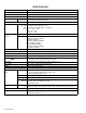
SPECIFICATION Items Contents Dimensions (W × H × D) 81.2cm × 58.4cm × 52.0cm Mass 41kg TV RF System Colour System B, G, I, D, K, M TV Mode PAL / SECAM / NTSC3.58 / NTSC4.43 Video Mode PAL / SECAM / NTSC3.58 / NTSC4.43 Stereo System Receiving Frequency A2 (B / G) / NICAM (B / G, I, D / K) VHF Low VHF High UHF CATV Intermediate Frequency 46.25MHz ~ 168.25MHz (AU0 ~ S10) 175.25MHz ~ 463.25MHz (E5 ~ S41) 471.25MHz ~ 863.
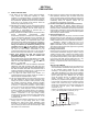
SECTION 1 PRECAUTION 1.1 SAFETY PRECAUTIONS (1) The design of this product contains special hardware, many circuits and components specially for safety purposes. For continued protection, no changes should be made to the original design unless authorized in writing by the manufacturer. Replacement parts must be identical to those used in the original circuits. Service should be performed by qualified personnel only. (2) Alterations of the design or circuitry of the products should not be made.
SECTION 2 SPECIFIC SERVICE INSTRUCTIONS 2.1 FEATURES • • • • • • New chassis design enables use of an interactive on-screen control. Pure flat CRT produces fine textured picture in every detail. Wide range voltage (110V ~ 240V) for AC power input. With AUDIO/VIDEO/S-VIDEO/COMPONENT input terminals. I2C bus control utilizes single chip ICs. By means of AUTO PROGRAM, the TV stations can be selected automatically and the TV channels can also be rearranged automatically.
FRONT PANEL CONTROLS V MENU OK 3 5 2 1 R L/MONO IN (VIDEO-3) 4 CHANNEL VOLUME 6 7 POWER TV/VIDEO EXIT 8 9 10 11 1 HEADPHONE jack 7 VOLUME (-/+) buttons 2 IN (VIDEO-3) : VIDEO 8 TV/VIDEO EXIT buttons 3 IN (VIDEO-3) : AUDIO L/MONO 9 Remote control sensor 4 IN (VIDEO-3) : AUDIO R 10 ECO sensor 5 MENU (OK) button 11 POWER lamp 6 CHANNEL (-/+) buttons 12 MAIN POWER button 12 REAR TERMINAL VIDEO-1 INPUT TERMINAL 1 5 VIDEO-1 INPUT 6 8 10 11 COMPONENT (VIDEO-2) INPUT V
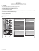
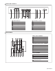
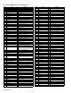
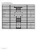
2.3 MAIN CPU [MAIN PWB : IC701] PIN FUNCTION Pin no. 1 2 3 4 5 6 7 8 9 10 11 12 13 14 15 16 17 18 19 20 21 22 23 24 25 26 27 28 29 30 31 32 33 Pin name VssP2 VssC4 V1.8C4 V3.
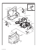
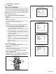
SECTION 3 DISASSEMBLY 3.1 DISASSEMBLY PROCEDURE 3.1.1 REMOVING THE REAR COVER • Unplug the power cord. (1) Remove the 16 screws [A] as shown in Fig.1. (2) Withdraw the REAR COVER toward you. CAUTION: When reinstalling the rear cover, carefully push it inward after inserting the MAIN PWB into the REAR COVER groove. 3.1.2 REMOVING THE CHASSIS (CHASSIS BASE AND CONTROL BASE) • Remove the REAR COVER.
[FRONT SIDE] CONTROL BASE E F FRONT CABINET (X2) G PICTURE TUBE CHASSIS BASE SPEAKER CRT SOCKET PWB Fig.2 FRONT CONTROL PWB (2/2) CLAW B (under side) FRONT CONTROL PWB (1/2) MAIN PWB FBT SPEAKER Fig.2 AV TERMINAL BOARD G (X2) CONTROL BASE CHASSIS BASE CLAW B (under side) D C (×4) REAR COVER A (×16) Fig.1 1-8 (No.
3.2 REPLACEMENT OF MEMORY IC 3.2.1 MEMORY IC This TV uses the following memory IC. Memory IC: IC702 on MAIN PWB The memory IC memorizes data for correctly operating the video and deflection circuits. When replacing the memory IC, be sure to use the same type IC written with the initial values of data. In other words, use the specific IC listed in "PRINTED WIRING BOARD PARTS LIST". For its mounting location, refer to "ADJUSTMENT LOCATIONS". 3.2.
3.2.
SETTING OF BASIC FUNCTIONS Setting item SERVICE MENU SETTING ITEMS Setting item Setting value POWER Off SUB POWER On VOLUME 15 COLOR SYSTEM PAL SOUND SYSTEM B/G PICTURE MODE (VSM) BRIGHT CINEMA SURROUND OFF OFF TIMER OFF STEREO MODE STEREO CHANNEL POSITION PR1 Table 2 1. VCO 2. DELAY POINT 2. V/C 1. SCREEN 2. CUTOFF(B/G) 3. WDR(R/G/B) 4. BRIGHT(TV/VDO 1/2/3) 5. CONT(TV/VDO 1/2/3/TV 16:9/VDO 16:9) 6. COLOUR(TV/VDO1/2/3/DVD) 7. TINT(TV/VDO 1/2/3) 8. SHARP [Do not adjust] 9.
3.3 REPLACEMENT OF CHIP COMPONENT 3.3.1 CAUTIONS (1) Avoid heating for more than 3 seconds. (2) Do not rub the electrodes and the resist parts of the pattern. (3) When removing a chip part, melt the solder adequately. (4) Do not reuse a chip part after removing it. 3.3.2 SOLDERING IRON (1) Use a high insulation soldering iron with a thin pointed end of it. (2) A 30w soldering iron is recommended for easily removing parts. 3.3.3 REPLACEMENT STEPS 1. How to remove Chip parts 2.
SECTION 4 ADJUSTMENT 4.1 ADJUSTMENT PREPARATION (1) You can make the necessary adjustments for this unit with either the remote control unit or with the adjustment equipment and parts as given below. (2) Adjustment with the remote control unit is made on the basis of the initial setting values, however, the new setting values used for setting the screen to its optimum condition may differ from the initial settings. (3) Make sure that AC power is turned on correctly.
4.5 ADJUSTMENT LOCATIONS FRONT CONTROL PWB ASS’Y (1/2) FRONT CONTROL PWB ASS’Y (2/2) SPEAKER (R) SPEAKER (L) FRONT S805 S801 S803 S804 S806 S802 S901 W J804 J803 J802 ROTATION COIL CNDEG J801 FRONT CN00S R CN002 CN001 PW POWER CORD DEG COIL MAIN PWB ASS’Y FRONT CN001 CN00W CN002 IC702 T 1 8 I2C CN00C 1. 5V 2. SCL0 3. SDA0 4. SCL1 5. SDA1 6. GND IC701 GND DEF YOKE HV 5V 6 6 1 6 1 1 HVT U GND B1 J805 J801 J802 J803 J804 5 TU001 1 CN00X UPPER : FOCUS 1. B1 2. NC 3.
4.6 BASIC OPERATION IN SERVICE MENU Operate the SERVICE MENU with the remote control unit. 4.6.1 SERVICE MENU ITEMS With the SERVICE MENU, various settings (adjustments) can be made, and they are broadly classified in the following items of settings: 1. IF 2. V/C 3. AUDIO 4. DEF 5. VSM W/B 6. STATUS 7. PLUG & PLAY (ON) For entering/adjusting the setting values (adjustment values) of the IF circuit. For entering/adjusting the setting values (adjustment values) of the VIDEO circuit.
4.6.3 SERVICE MENU FLOW CHART 1. IF SERVICE MENU SERVICE MENU IF SERVICE MENU 1. IF 2. V/C 3. AUDIO 4. DEF 5. VSM W/B 6. STATUS 7. PLUG & PLAY (ON) 1-7 : SELECT VCO (CW) TOO HIGH ABOVE REFERENCE JUST REFERENCE BELOW REFERENCE TOO LOW *****MHz 1. VCO 2. DELAY POINT DISPLAY : EXIT ******* **** ***** ***** **** **** *** *** DELAY POINT AGC TAKEOVER ** 2. V/C Setting item V/C PAL 1. SCREEN HBC WBC BRI 6. STATUS 1. SCREEN 2. CUTOFF (B/G) 3. WDR (R/G/B) 4. BRIGHT (TV/VDO1/2/3) 5.
4.7 ADJUSTMENT PROCEDURE 4.7.1 B1 VOLTAGE Measuring instrument Item Test point Adjustment part B1 (pin 1) GND (pin 5) [CN00X DC voltmeter connector in MAIN PWB] B1 VOLTAGE check Signal generator Description (1) Receive a black and white signal. (2) Connect a DC voltmeter between B1 and GND (between pins 1 and 5 of the connector CN00X). (3) Make sure that the voltage is DC134.5V ± 2V. 4.7.
4.7.4 VIDEO CIRCUIT ADJUSTMENTS • The setting (adjustment) using the remote control unit is made on the basis of the initial setting values. • The setting values which adjust the screen to the optimum condition can be different from the initial setting values. • Do not change the initial setting values of the setting (adjustment) items not listed in "ADJUSTMENT PROCEDURE". • The initial setting values in parenthesis ( ) are fixed offset values, needing no further adjustment.
Item WHITE BALANCE (High light) adjustment Measuring instrument Test point Adjustment part [2. V/C] 3. WDR (R) 3. WDR (G) 3. WDR (B) Signal generator Remote control unit V/C PAL (R) (G) (B) 3. WDR ** (**) ** (**) ** (**) Description Notes: • Proceed to the following adjustment after having completed the WHITE BALANCE (Low light) adjustment. • Set PICTURE MODE (VSM) to "BRIGHT". (1) Receive a PAL black and white signal (colour off). (2) Select 2. V/C from the SERVICE MENU. (3) Select 3.
Item Measuring instrument Test point Adjustment part SUB COLOUR 1 Remote adjustment control unit [2. V/C] 6. COLOUR SUB COLOUR 2 Signal adjustment generator TP-47G [2. V/C] TP-E 6. COLOUR [CRT SOCKET Oscilloscope PWB] Remote control unit B M R (A) C W 1-20 (No.YA139) Y G (–) 0V (+) Description [Method of adjustment without measuring instrument] Notes: • Proceed to the following adjustment after having completed the SUB CONTRAST adjustment. • Set PICTURE MODE (VSM) to "BRIGHT".
Item SUB TINT 1 adjustment Measuring instrument Test point Adjustment part Signal generator [2. V/C] 7. TINT Description [Method of adjustment without measuring instrument] Notes: • Proceed to the following adjustment after having completed the SUB CONTRAST adjustment. • Set PICTURE MODE (VSM) to "BRIGHT". Remote control unit - NTSC 3.58 TINT (1) Receive a NTSC 3.58 colour bar signal (full field colour bar 75% white). (2) Press the [COLOUR SYSTEM] key to select the NTSC 3.58 colour system.
4.7.6 DEFLECTION CIRCUIT ADJUSTMENTS • The setting (adjustment) using the remote control unit is made on the basis of the initial setting values. • The setting values which adjust the screen to the optimum condition can be different from the initial setting values. • When performing deflection circuit adjustment, adjusts PAL signal (fv: 50 Hz) in 4:3 mode and 16:9 mode respectively, and adjust the NTSC signal (fv: 60 Hz) similarly.
Measuring instrument Item V. HEIGHT adjustment Test point Adjustment part Signal generator [4. DEF] 3. V-SIZE 14. V-ZOOM Remote control unit Screen size 92% H. POSITION adjustment Picture size 100% Signal generator [4. DEF] 4. H-CENT Remote control unit C H. WIDTH adjustment [4.DEF] 5. H-SIZE Remote control unit Screen size 91% - PAL V. HEIGHT (1) Receive a PAL crosshatch signal. (2) Select 3. V-SIZE. (3) Set the initial setting value of 3. V-SIZE. (4) Select 14. V-ZOOM.
Item SIDE PIN adjustment Measuring instrument Test point Adjustment part [4. DEF] 7. EW-PIN Signal generator Remote control unit Straight TRAPEZIUM adjustment Signal generator [4.DEF] 6. TRAPEZ Parallel Signal generator - PAL TRAPEZIUM (1) Receive a PAL crosshatch signal. (2) Select 6. TRAPEZ. (3) Set the initial setting value of 6. TRAPEZ. (4) Adjust 6. TRAPEZ so that the vertical lines at the left and right edges on the screen are in parallel.
Item CORNER PIN adjustment Measuring instrument Test point Signal generator Adjustment part [4. DEF] 8. COR-UP 9. COR-LO Remote control unit Straigt Description - PAL CORNER PIN (1) Receive a PAL crosshatch signal. (2) Select 8. COR-UP. (3) Set the initial setting value of 8. COR-UP. (4) Select 9. COR-LO. (5) Set the initial setting value of 9. COR-LO. (6) Adjust 8. COR-UP and 9. COR-LO so that the vertical lines at the four corners on the screen are straight.
COMPRESS : ON (16:9) Measuring instrument Item V. HEIGHT adjustment Test point Signal generator Adjustment part [4.DEF] 14. V. ZOOM 3. V-SIZE Remote control unit Screen size Vertical amplitude Screen size Description - PAL V. HEIGHT (1) Receive a PAL crosshatch signal of vertical frequency 50Hz. (2) Press the [MENU] key and select PICTURE. (3) Select PICTURE FEATURES. (4) Select COMPRESS (16 : 9) and set COMPRESS to ON. (5) Select 4. DEF from the SERVICE MENU.
Item SIDE PIN adjustment Measuring instrument Test point Signal generator Adjustment part [4. DEF] 7. EW-PIN Remote control unit Straight TRAPEZIUM adjustment Signal generator [4. DEF] 6. TRAPEZ Parallel Signal generator Straigt - PAL TRAPEZIUM PIN (1) Receive a PAL crosshatch signal. (2) Select 6. TRAPEZ. (3) Set the initial setting value of 6. TRAPEZ. (4) Adjust 6. TRAPEZ so that the vertical lines at the left and right edges on the screen are in parallel.
VIDEO - 2 SET: COMPONENT Item H. POSITION adjustment Measuring instrument Test point Adjustment part Signal generator [4. DEF] 4. H-CENT Remote control unit C D Description (1) Receive a PAL circle pattern signal to VIDEO-2 component terminal. (2) Select VIDEO-2 SET from the MENU and set VIDEO-2 SET to COMPONENT. (3) Select 4. DEF from the SERVICE MENU. (4) Select 4. H-CENT. (5) Set the initial setting value of 4. H-CENT. (6) Adjust 4. H-CENT to make "C=D".
4.7.8 PURITY AND CONVERGENCE PURITY ADJUSTMENT Note: The final adjustment of CONVERGENCE must be done after the FOCUS adjustment. (CONVERGENCE is changed by FOCUS adjustment.) When makes difference by FOCUS adjustment, should be reconfirming PURITY adjustment. WEDGE DEFLECTION YOKE P CRT 46 (1) Demagnetize CRT with the demagnetizer. P/C MAGNETS (2) Loosen the retainer screw of the deflection yoke. (3) Remove the wedges.
STATIC CONVERGENCE ADJUSTMENT (1) Input a crosshatch signal. (2) Using 4-pole convergence magnets, overlap the red and blue lines in the centre of the screen (Fig.1) and turn them to magenta (red/blue). (FRONT VIEW) (3) Using 6-pole convergence magnets, overlap the magenta (red/blue) and green lines in the centre of the screen and turn them to white. Fig.1 (4) Repeat 2 and 3 above, and make best convergence.
SECTION 5 TROUBLESHOOTING 5.1 SELF CHECK FUNCTIONS 5.1.1 OUTLINE This model has self check functions given below. When an abnormality has been detected, the SUB POWER is turned off and POWER LED flashes to inform of the failure. An abnormality is detected by the signal input state of the control line connected to the microcomputer. 5.1.2 SELF CHECK ITEMS Check item Details of detection B1 over-current protection An over-current on the low B1 line is detected.
1-32 (No.
Victor Company of Japan, Limited AV & MULTIMEDIA COMPANY VIDEO DISPLAY CATEGORY 12, 3-chome, Moriya-cho, kanagawa-ku, Yokohama, kanagawa-prefecture, 221-8528, Japan (No.