AV-P960E INSTRUCTIONS (A) Français MANUEL D’INSTRUCTIONS: PRESENTOIR NUMERIQUE BEDIENUNGSANLEITUNG : DIGITALEN VORFÜHRERS MANUALE DI ISTRUZIONI : DIGITAL PRESENTER Italiano Deutsch AV-P960E DIGITAL PRESENTER English DIGITAL PRESENTER ® ® is a registered trademark owned by Victor Company of Japan, Ltd. is a registered trademark in Japan, the U.S.A., the U.K. and many other countries.
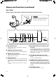
Safety Precautions For Europe 䡵 Dimensioni (LHP) (apparecchio: mm) IMPORTANT WARNING: The wires in this mains lead are coloured in accordance with the following code: GREEN - and - YELLOW: EARTH BLUE: NEUTRAL BROWN: LIVE As the colours of the wires in the mains lead of this apparatus may not correspond with the coloured markings identifying the terminals in your plug, proceed as follows.
Table of Content Safety Precautions .................................................................... 2 Features ..................................................................................... 2 Getting Started Precautions ................................................................................ 4 Names and Functions ............................................................... 5 Overall View .......................................................................................
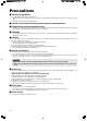
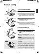
Precautions 䡵 Handling of Equipment ● Use the handle on the side to carry this unit. Carrying this unit by its camera head, camera arm or its side illumination lamps might cause them to be deformed or damaged. ● Pull out the handle slowly in a straight manner. 䡵 Conduct prior functional checks before important shooting events.
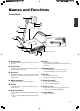
Names and Functions Overall View English 1 0 ! 2 Rear Panel ☞ Page 7 3 4 4 Right Side @ 5 6 7 Control Panel ☞ Page 6 8 1 Camera Head For capturing images of objects on the stage or surrounding areas. 2 Camera Arm Supporting arm for the camera head. Adjust its angle when shooting 3-dimensional objects. 3 Arm Lock For adjusting the length of camera. Release the lock when retracting or extending the camera arm and lock it at the adjusted position.
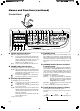
Names and Functions (continued) Control Panel # @ ! 0 9 8 7 6 5 4 3 2 1 USER SETUP DEFAULT USER SAVE DELETE WHITE BALANCE AUTO CAMERA RED PICTURE MEMORY 1 2 3 PAGE NEGA POSI BW COLOUR SAVE LIGHT TEXT IMAGE SELECT ENTER SD CARD % ^ & BRIGHT CAMERA AUTO FOCUS ZOOM EXT IN OUT IN SOURCE SELECT * 1 [ZOOM] Adjustment Buttons Adjust in accordance with the object. [IN] : To shoot objects (materials) in an enlarged form.
~ 0 are functional only if SD card is inserted into the SD Slot. 7 [IMAGE SELECT/ENTER] Button for Selecting Images Displays the miniature images of the SD card in a view of 16. ☞ Page 21 ‘Viewing Image Data Stored in SD Card’ 8 [SAVE] Button for Saving SD Card While selecting images from the camera, if this button is pressed for more than 2 seconds, the indicator lamp will blink and the image currently displayed will be stored in the SD card.
Names and Functions (continued) Rear Panel Refer to page 10 ‘Connection’ for details on connecting with other devices. Caution Do not open the cover at the bottom of the arm and put your finger or insert object into it. This may cause malfunction or injury. 1 AC IN 2 345 6 7 8 USB MONITOR OUTPUT RGB OUTPUT EXT INPUT REMOTE INPUT (RS-232C) NTSC 1 [AC IN] Power Inlet Connect using the power cord supplied to an AC 100 V ~ AC 240 V power source.
Before Using Install according to the following steps. Right Illumination Left Illumination 1. Lift up the right illumination 2. Lift up the left illumination 3. Lift up the camera head (camera arm) English 1. 2. Hold the camera arm and hold down the unit firmly while slowly lifting the camera head until it reaches its maximum position and stops. 4. Camera Head 4. Releasing the arm lock Pull the lever of the arm lock in the direction of the arrow as shown in the figure to release the lock.
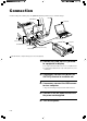
Connection Install according to the following steps. The [MONITOR OUTPUT] terminal is use to confirm the images. LCD Monitor Computer 2. [MONITOR OUT] [RGB OUT] 5. 3. [USB] Terminal Power Switch USB Terminal Projector Left Illumination [AC IN] 4. 1. (supplied power cord) AC Power The LCD monitor, computer and projector are sold separately. 1. Connect the [RGB OUTPUT] terminal to a projector or display. ● The output of this unit is XGA, connect it to a compatible device.
Presenting Printed Materials Camera Head 1. Arm 1. 1. Adjusting the arm and camera head Adjust the arm and camera head in accordance with the size of the object. 2. ● Ensure that the camera head is positioned at the centre of the object. 2. ● The arm is catered to capture an A3 landscape equivalent object when fully extended. [BRIGHT] button [ZOOM] button 2. Adjusting lighting Adjust such that the object is evenly lighted. [FOCUS] button 3.
Presenting 3-dimensional Objects 3-D object placed on the stage can be captured. In addition, by adjusting the angle of the arm, the 3-D object can be captured at various angles. 1. 1. Adjusting the arm and camera head Adjust the arm and camera head in accordance with the size of the object. ● Ensure that the camera head is positioned at the centre of the object. ● The arm is catered to capture an A3 landscape equivalent object when fully extended. 2. 2. 2.
Shooting Surrounding Objects Camera Head 1. Turn the camera head towards the object 2. Remove the close-up lens English The camera head can be turned to shoot the surrounding objects. 1. Press and hold the claws while pulling out the lens. 3. Adjusting the image Adjust the zoom, brightness and focus. 2. Close-up lens 3.
Presenting Slide Films Slide films with frame can be inserted directly into the camera head for presentation. 1. Place a piece of white paper on the stage As the slide film makes use of the reflecting light from the stage surface, place a highly reflective white paper (B4 size or A3 size) on the stage. 2. 2. 1. [BRIGHT] button 2. Adjusting side illuminations Adjust such that the stage surface is evenly lighted. te Whi er pap [ZOOM] button 3.
Presenting Films and Other Transparent Materials Films can be placed on the stage for presentation. Press the [LIGHT] button to turn on the back illumination English 1. The lighting source changes whenever the [LIGHT] button is pressed. Side illuminations Back illumination 2. Back illumination All illuminations off Place the films and other transparent materials on the stage Place the film at the centre of the stage and adjust the camera head directly on top of the film. 1. [LIGHT] button 3.
Capturing Images Through a Microscope Images from the microscope can be captured by aligning the view piece of the microscope with the camera head. The procedures described below are for using the adaptable microscope ECLIPSE E200 from Nikon. 4. 1. 3. Setting the microscope ● Prepare the microscope, such as focus adjustment, for viewing. ● For the usage of the microscope, refer to the instruction manual of the microscope. 2. Place the microscope on a platform of about 10 cm high 3.
Saving Images in the Picture Memory Frequently used images can be saved in the picture memory of this unit. Switching between camera images and images from the picture memory is possible while presentation is in progress. Up to 3 images can be saved. Press the [CAMERA] button English 1. The camera image is outputted. [BRIGHT] button Button Indicator Lamp [ZOOM] [FOCUS] button button 2. Adjusting zoom 3. Adjusting brightness 4. Adjusting focus 5.
Adjusting the White Balance 䡵 Adjusting the White Balance Automatically This unit is adjusted to display the natural colour. However, the white balance can be re-adjusted with the following steps. 1. Place a piece of white paper on the stage 2. Adjusting zoom Adjust till the full screen becomes white. White paper 3. Adjusting brightness 4. Press the [WHITE BALANCE AUTO] button The white balance will be re-adjusted in about 5 seconds.
Saving the Settings (User Setting Registration) 䡵 Registration 1. Adjusting the camera ● Adjust the camera to the settings to be registered. ● The following user settings are possible. ( ) are factory settings. • Zoom position (Approximately A4 portrait position) • Lighting status (Both side illuminations light up) • White Balance (Value corresponding to side illumination) • Nega/Posi (Posi) • Black & White/Colour (Colour) • Text (OFF) 2.
Storing Images in SD Card Images taken can be stored in the SD card (sold separately). 1. Press the [CAMERA] button 2. Insert the SD card ● To remove the SD card, push in the card before removing it from the card slot. 1. 3. ● The save indicator lamp lights up ➞ Blinks while saving is in progress. Blinks ➞ Lights up ➞ Light goes off once saving is completed. (about 2 seconds) ● Saving is not possible if the SD card switch has been turned on to write-protect.
Viewing Image Data Stored in SD Card 5. 1. 1. 2. 3. Insert the SD card Press the [SD CARD SYSTEM] buttons Viewing images DELETE SAVE PAGE IMAGE SELECT ENTER SD CARD Press the [PAGE] buttons FREEZE LIGHT EXT IN ● The image switches whenever the button is pressed. ● The image will switch continuously if the button is pressed and held. (at an interval of about 0.5 seconds) CAMERA Note SD CARD SYSTEM 3.
Connecting to Computer via the USB Connector By connecting to the computer, image data or image memory stored in the SD card as well as image data stored in this unit can be downloaded to the computer. 䡵 Compatible Computers OS: Windows姞 Me/2000/XP 䡵 When connecting for the first time With the Windows’ plug and play capability, the necessary driver will be installed automatically for this unit to be recognized by the computer. Install according to the instructions displayed on the screen.
Operating the Remote Control Unit The following functions are available with the use of the remote control unit. 1 2 3 English 1 [CAMERA] To output the camera images. (☞ Page 6 5 [SOURCE SELECT] Buttons) 2 [FREEZE] CAMERA FREEZE IMAGE SEL. SD CARD 8 AUTO BRIGHT AUTO FOCUS AUTO WHITE To make the camera image still. (☞ Page 6 4 [FREEZE] Button) EXT-IN OUT IN ZOOM 4 5 6 7 3 [EXT-IN] The images of the device connected to the [EXT INPUT] terminal will be outputted.
Installing LCD Monitor Connect commercially available LCD monitor to the [MONITOR OUTPUT] terminal. It is convenient for adjusting viewing angle. 1. Mount the LCD monitor mounting bracket (AV-ZK10, sold separately) to the LCD monitor using the screw supplied with the bracket. 2. Mount the LCD monitor mounting bracket (AV-ZK10, sold separately) to this unit using the screw supplied with the bracket. 3. Connect the LCD monitor to the [MONITOR OUTPUT] terminal of this unit with a video cable 4.
Troubleshooting When you encounter a problem, check the following points for a solution. If the problem persists, stop using this unit and consult your nearest JVC dealer. No image appears. Focusing is not possible.
Specifications 䡵 GENERAL Power requirements Current consumption Mass : AC 100 V to 240 V 50 Hz / 60 Hz : 0.5 A : 5.6 kg (12.3 lbs.) 䡵 OPTICAL Lens Shooting area Focal distance adjustable range Zoom Focus Brightness : F1.8 to F2.8, f = 5.4 mm to 64.8 mm (12 times) : Max.: 376 mm x 282 mm (14-4/5" x 11-1/10") (A3 landscape equivalent) : From the stage surface to a height of 50 mm (1-31/32") from the stage surface (the camera directed downward, with close-up lens) ∞ to 0.8 m (2.
378 English 䡵 Dimensions (WHD) (unit: mm) 190 (When folded) 653 (When extended to A3) 495 (When folded) 491 (When extended) Specifications and appearance of this unit are subject to change for improvements without prior notice.