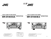
U R VIDEO CASSETTE RECORDER BR-DV600UA E R VIDEO CASSETTE RECORDER INSTRUCTIONS BR-DV600EA OPERATE CH-1/3 ON/OFF OPERATE CH-1/3 ON/OFF VIDEO CASSETTE RECORDER BR-DV600UA VIDEO CASSETTE RECORDER BR-DV600EA REC LEVEL REC LEVEL EJECT MENU ADVANCE PRESET REC CH-2/4 PHONES INSTRUCTIONS HOLD SHIFT– SHIFT SELECT SET V.IN/A.MONI A.OUT DV LINE Y/C L MIX R PLAY COUNTER CH-1/2 MIX CH-3/4 MENU PAUSE SHIFT+ A.
U E Supplement This equipment is in conformity with the provisions and protection requirements of the corresponding European Directives. This equipment is designed for professional video appliances and can be used in the following environments: 1. 2. 3. 4. 5. 6. 7. 8. 9. 10. 11. 12. 13. 14. 15. 16. 17. 18. 19. 2U 2 5 residential area (in houses) 5 commercial and light industry; e.g. office or theatres 5 urban outdoors Read all of these instructions. Save these instructions for later use.
U SAFETY PRECAUTIONS CAUTION ATTENTION RISK OF ELECTRIC SHOCK DO NOT OPEN RISQUE D’ELECTROCUTION NE PAS OUVRIR CAUTION: TO REDUCE THE RISK OF ELECTRIC SHOCK, DO NOT REMOVE COVER (OR BACK). NO USER-SERVICEABLE PARTS INSIDE.
1 INTRODUCTION CONTENTS 1 INTRODUCTION 1-1 1-2 1-3 1-4 7 PLAYBACK Major features .............................................. Maintenance ................................................ Precautions .................................................. Precautions for use of head cleaning tape .............................................................. 5 5 6 7 Front panel ................................................... 8 Rear panel ...................................................
1 INTRODUCTION 1 INTRODUCTION 1-3 Precautions 1-4 Precautions for use of head cleaning tape Installation and storage Cassette tape 5 To avoid malfunctions or damage to your recorder, do 5 Type not use or store it in places subject to the following conditions. – Extreme heat or cold — temperature outside the allowable range (5˚C to 40˚C) – Strong magnetic fields (generated by transformers, motors, etc.
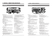
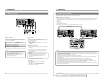
2 CONTROLS, CONNECTORS AND DISPLAYS 2 CONTROLS, CONNECTORS AND DISPLAYS 2-1 Front panel 2-2 Rear panel # $ % ^ 1 REC LEVEL DV IN/OUT $ Y/C COMPONENT VIDEO LINE EJECT MENU REC 0 HOLD SHIFT SHIFT SELECT SET V.IN/A.MONI A.OUT DV LINE Y/C L MIX R SHIFT A.
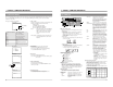
2 CONTROLS, CONNECTORS AND DISPLAYS 2 CONTROLS, CONNECTORS AND DISPLAYS 2-3 On-screen display 2-4 LCD display The on-screen display can be viewed on a monitor connected to the rear panel’s [VIDEO MONITOR OUT] connector when the No. 500 menu switch is set to “ON”. Pressing the [MENU] button will bring up the menu switch display regardless of this setting. 6 Five types of indication are available. 5 Tape counter Time display STOP TCR 1 2 : 0 0 : 0 0 : 0 0 1.
3 CONNECTIONS 3 CONNECTIONS 3-2 Audio system connections 3-1 Video system connections Sync signal generator, etc. Video output from a VCR, etc.
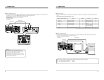
3 CONNECTIONS 3 CONNECTIONS 3-3 Other connections 3-4 Editing system examples The BR-DV600UA/EA can be used as a feeder for different video formats. 5 Simplified digital cut editing system DV IN/OUT COMPONENT VIDEO LINE Using an editing remote controller with JVC bus specifications such as the RM-G800/G805, digital cut editing is possible with another MiniDV VCR. When the BR-DV600UA is used as a recorder, the following editing operations cannot be performed.
3 CONNECTIONS 3 CONNECTIONS 5 Edit adjust setting 5 Mixed S-VHS/VHS system This is an editing system which uses the BR-DV600UA as a feeder/player with an RS-422A serial remote controller such as the RM-G820. In this case, the BR-DV600UA cannot be used as a recorder VCR. The S-VHS/VHS VCR can be replaced with a D-9/Betacam VCR. The following editing operations are not available.
3 CONNECTIONS 4 MENU SWITCHES You can set menu switches using either the on-screen display or the counter display. To set switches on the on-screen display, you will need to connect a monitor to the VCR’s [VIDEO MONITOR OUT] connector. This section explains how to set switches using the on-screen display. The same procedures apply to switch setting on the counter display, the only difference being that each menu switch item is indicated by numeric code rather than by name.
4 MENU SWITCHES 4 MENU SWITCHES 4-2 Menu switch details For switch setting procedures, refer to “Menu switch setting procedure”. q: Factory setting (00): The number in the bracket shows the set value on the counter display. 002 OPERATION LOCK Details: Switches the operation lock ON/OFF. Setting: qOFF (00): The operation lock is OFF: all operations are enabled. ON (01): The operation lock is ON: all controls are disabled except for the [MENU] button.
4 MENU SWITCHES 4 MENU SWITCHES q: Factory setting (00): The number in the bracket shows the set value on the counter display. q: Factory setting (00): The number in the bracket shows the set value on the counter display. 312 AUTO REW Details: Selects whether or not the tape is rewound automatically at tape end during recording or playback. Setting: qOFF (00): The tape is not rewound automatically. ON (01): The tape is rewound automatically. Repeat playback is available when No.
5 PREPARATION 5 PREPARATION Preparing this unit for recording or playback. Built-in clock setting Time data is recorded in the sub code area of the tape during recording. In the Play mode, this data is read out and can be shown on the on-screen display or the counter display. OPERATE CH-1/3 ON/OFF [OPERATE] button VIDEO CASSETTE RECORDER BR-DV600UA REC LEVEL EJECT MENU PHONES HOLD SHIFT SHIFT SET V.IN/A.MONI A.OUT DV LINE Y/C L MIX R SHIFT A.
6 RECORDING 6 RECORDING [REC LEVEL] control [REC LEVEL] control OPERATE CH-1/3 OPERATE CH-1/3 ON/OFF ON/OFF VIDEO CASSETTE RECORDER BR-DV600UA VIDEO CASSETTE RECORDER BR-DV600UA REC LEVEL MENU ADVANCE PRESET REC CH-2/4 PHONES REC LEVEL EJECT HOLD SHIFT SHIFT SELECT SET V.IN/A.MONI A.OUT DV LINE Y/C L MIX R SHIFT A.
7 PLAYBACK Playback 1 Press the [PLAY] button. OPERATE CH-1/3 ON/OFF [OPERATE] button VIDEO CASSETTE RECORDER BR-DV600UA REC LEVEL 3 To temporarily stop playback, press the [PAUSE] ADVANCE PRESET REC CH-2/4 PHONES 2 To stop playback, press the [STOP] button. EJECT MENU HOLD SHIFT SHIFT SELECT SET V.IN/A.MONI A.OUT DV LINE Y/C L MIX R SHIFT A.
8 EXTERNAL TIMER-START FUNCTION 9 TIME CODE (AUTOMATIC START-UP WITH POWER SUPPLY) The time code is recorded frame by frame together with the materials to be recorded on the tape. With this time code, the position of the materials can be precisely specified, improving the editing accuracy and working efficiency. (The editing accuracy of 0 frame may not be obtained even though the time code is used, depending on the performance of the VCR and editing controller and influence of editing system.
9 TIME CODE 9 TIME CODE 1 Set the menu switches. ( See pages 22 and 23.) 5 Set the No. 413 menu switch to H H H M M M S S S F F F OPERATE CH-1/3 “INTERNAL”. 5 Set the No. 414 menu switch to “PRESET”. 5 Set the No. 415 menu switch. Setting is not necessary for user bits. REC RUN: The time code is counted only during recording. FREE RUN: The time code is counted after the preset is complete. 5 Set the No. 416 menu switch.
10 SUPER SCENE FINDER FUNCTION 9 TIME CODE 5 Recording time code from an external time code generator ● Menu switch setting No. 413 ......... EXTERNAL Operation 1 Record. Press the [PLAY] button while pressing the [REC] button. [ The [SLAVE] indicator lights in the LCD display and the time code and user bits from the external time code generator are recorded on the tape. During recording, time code recording continues even after the end of the input regenerated time code.
11 BACKUP RECORDING FUNCTION Long-time series recording is possible by connecting other DV recorders in series. 5 Backup recording 12-1 Command tables 5 Operation 1. Start recording with the source VCR. * Be sure to start from the beginning of the tape. Source VCR DV camcorder GY-DV500/DV550 or JVC DV camcorder 12 RS-232C INTERFACE 2. Recording with this unit starts around the time when the tape in the source VCR ends. • Recording starts at the time set with the No.
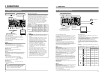
12 RS-232C INTERFACE 12 RS-232C INTERFACE 12-2 RS-232C specifications 12-3 RS-232C commands 9PIN D-Sub ASCII code table Use this table to express the values or alphabets on the RS-232C interface. 1 2 34 5 0 6 Pin NO. Signals 9 Operations Direction of signals 2 RXD Receive data VTR p PC 3 TXD Transmit data VTR [ PC VTR [ PC 4 DTR Data terminal ready 5 GND Signal ground 6 DSR Data set ready VTR p PC Note: PC means a controller such as a personal computer.
12 RS-232C INTERFACE 12 RS-232C INTERFACE Commands Description Setting (preset) commands B5 Shuttle play. The search speed is specified by sending the speed code data after this command (see the table below). These commands activate various settings on the VCR. When a command is sent, the corresponding setting is activated. F-SHUTTLE Speed code table (corresponding speed) Speed code 30h 31h 33h 34h 35h 36h 37h 38h Search speed Still 0.1 0.2 0.3 1 2 5 10 B6 R-SHUTTLE Shuttle reverse play.
12 RS-232C INTERFACE Contents of STATUS SENSE When the STATUS SENSE (D7H) command is sent, the following data (5 bytes) is returned. 12 RS-232C INTERFACE Fourth byte Bit No. Status 7 PLAY MODE 6 FF MODE First byte Bit No. Status 7 6 5 4 3 2 1 0 Always 1 Always 0 SHORT FF/REW REC INHIBIT CASSETTE OUT SERVO LOCK Undefined ERROR When the bit is 1 During short FF or short REW Recording is inhibited. There is no cassette loaded. Servo is locked. Always 0 An error has occurred. Second byte Bit No.
12 RS-232C INTERFACE Menu switch setting command ED MEMORY SW PRESET Use this command to change the VCR’s menu switches. Transmit the data (3 bytes) corresponding to the menu switch to be changed, following this command. (e.g.) Set No. 108
13 TROUBLESHOOTING 13 TROUBLESHOOTING 13-1 Warning indicators On-screen display Counter display If the unit malfunctions during operation, the built-in self-diagnostics system identifies the problem and displays a warning message on the monitor and/or the counter display. Also, the [AUTO OFF] indicator may be shown on the LCD. In this case, turn the power off and then on again to restore operation. If the [AUTO OFF] indicator appears again, the VCR may require repair or adjustment.
13 TROUBLESHOOTING 15 SPECIFICATIONS 13-2 Other problems General 5 Power • The [REMOTE] switch is set to “REMOTE”. • The No. 002 menu switch is set to “ON”. • Set the [REMOTE] switch to “LOCAL”. • The monitor is not connected to the [MONITOR OUT] connector. • The No. 500 menu switch is set to “OFF”. • Connect the monitor to the [MONITOR OUT] connector. • Set the No. 500 menu switch to “ON”. Noise appears on parts of the playback picture.