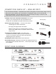
For models: C-13010 C-13011 C-20010 AV-20020 AV-20021 AV-27015 AV-27020 COLOR TELEVISION USER’S GUIDE (Illustration of AV-27020 and RM-C345) IMPORTANT NOTE TO THE CUSTOMER: In the spaces below, enter the model and serial number for your television (located on the rear of the television cabinet). Staple your sales receipt or invoice to the inside cover of this guide. Keep this user’s guide in a convenient place for future reference. Keep the carton and original packaging for future use.
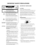
IMPORTANT SAFETY PRECAUTIONS CAUTION RISK OF ELECTRIC SHOCK DO NOT OPEN CAUTION:To reduce the risk of electric shock. Do not remove cover (or back). No user serviceable parts inside. Refer servicing to qualified service personnel. The lightning flash with arrowhead symbol, within an equilateral triangle is intended to alert the user to the presence of uninsulated “dangerous voltage” within the product’s enclosure that may be of sufficient magnitude to constitute a risk of electric shock to persons.
6 If an outside antenna is connected to the TV set, be sure the antenna system is grounded so as to provide some protection against voltage surges and built-up static charges. Section 810 of the National Electrical Code provides information with respect to proper grounding of the mast and supporting structure, grounding of the lead-in wire to an antenna discharge unit, size of grounding conductors, location of antenna discharge unit, connection requirements for the grounding electrode.
WELCOME! Congratulations on your new television purchase! We thank you for choosing JVC. We know you are anxious to start watching your new television, but before you operate it, please read this guide and then keep it handy for future reference. After all, you just bought a great TV with a lot of terrific features, you should know what each feature is and how to use it properly! Please note as you read through this guide, that there are illustrations of select models for your reference.
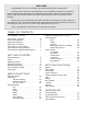
C O N N E C T I O N S 5 CONNECTIONS CHECKLIST — READ ME FIRST! The Connections Checklist — Read Me First! section of this guide is a list of ideas to keep in mind when you set out to perform your connections. It is designed to help us not-so-technicallyadvanced individuals. If you read this section, and can’t identify the plugs, connectors, and components you have, do not be afraid to seek help.
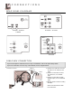
C O N N E C T I O N S REAR PANEL DIAGRAMS C-13010 • C-13011 C-20010 AV-20020 • AV-20021 AV-27015 AV-27020 CABLE BOX CONNECTION If you do not require a cable box to access any or all channels, refer to the Quick Setup Guide. If you use a cable box to access any or all channels, use the diagram below. Illustration of AV-27020 CABLE or ANTENNA OUT CABLE BOX VCR 1) Connect the cable wire out from the wall in to the cable box RF input.
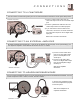
C O N N E C T I O N S 7 CONNECTING TO A CAMCORDER You can connect a camcorder right to your TV. For other video/VCR connections see the Quick Setup Guide. Illustration of AV-27020 1) Connect a white audio cable from the camcorder output into the TV’s Left Audio input jack. 2) Connect a yellow video cable from the camcorder output into the TV’s Video input jack. 3) If you have both a stereo model TV and camcorder, connect the red audio cable from the camcorder output into the TV Right audio input jack.
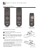
G E T T I N G S T A R T E D REMOTE CONTROLS RM-C345 RM-C340 RM-C241 AV-27020 AV-20020 • AV-20021 C-13010 • C-13011 C-20010 • AV-27015 CHANGING THE BATTERIES Be sure to use only size AA batteries. 1 Push down or raise the latch on the remote's back cover to remove it. 2 Insert the two supplied AA batteries, carefully noting the “+” and “–” markings on the batteries and remote control. To avoid a short circuit, insert “–” end first. 3 RM-C241 Snap the cover back into place.
G E T T I N G S T A R T E D 9 POWER ❒ Press the POWER button on the remote control or the TV front panel. The power lamp will glow red. (On the AV-27020 and AV-27015 the On Timer lamp will glow red.) ❒ Make sure that the TV/CATV switch is set to TV (RM-C340 and RM-C345 only). Switch to CATV only if you plan to operate a cable box. If you switch to CATV you will not be able to operate the TV functions with the remote, only the cable box functions! ❒ To turn the power off, press the POWER button again.
R E M O T E P R O G R A M M I N G SETTING THE CATV & VCR CODES Many CATV & VCR brands have more than one code. If the first code in the list does not work, try the other codes listed. If your CATV box or your VCR do not respond to any of the codes listed for the manufacturer and search code function, use the remote control for that accessory to operate it.
R E M O T E P R O G R A M M I N G 11 VCR SETUP FOR RM-C340 AND RM-C345 The remote is pre-programmed with the VCR codes for power on and power off, play, stop, fast-forward, rewind, and channel up and down. 1) Determine the correct code from the “VCR Codes” chart (below). 2) Slide the 2-Way Mode Selector Switch to TV. 3) Press and hold down the DISPLAY button. 4) Enter the 3-digit code with the 10 key pad while continuing to hold down the DISPLAY button. 5) Release the DISPLAY button.
U S I N G T H E USING THIS GUIDE: PICTURE SETTINGS Throughout this guide there are certain symbols we use as shorthand to show you what to do. When you see them, keep these factors in mind: Up and down arrows mean press the MENU UP or MENU DOWN buttons.
I N I T I A L S E T U P AUTO TUNER SETUP CHANNEL SUMMARY During Auto Tuner Setup, the TV will automatically scan through all available channels and memorize the active ones so that when you scan, you do not pick up weak or noisy channels. You can add or delete channels from the channel scanning. You can also lock out any “unauthorized” viewers from one or up to all 181 channels.
I N I T I A L S E T U P Continued … SET LOCK CODE CHANNEL GUARD - LOCK To CHANNEL SUMMARY To operate To the Lock column The access code zero (0) to lock or unlock that channel CH 01 02 03 04 05 ADD X X X X X – – – – – : : : : : : CH 06 07 08 09 10 ADD X – – X X The Lock Code locks and unlocks Channel Guard settings.
P I C T U R E S E T T I N G S TINT DETAIL Tint allows you to adjust the levels of red and green in the picture. Detail allows you to adjust the level of detail within the picture. Press the MENU button Press the MENU button To TINT To DETAIL To accentuate green To make the picture sharper To accentuate red To move to the next or previous To make the picture smoother To move to the next or previous COLOR NOISE MUTING Color allows you to adjust both the vividness and subtlety of the color.
NOTES: STEREO SETS ONLY!! Bass, Treble, Balance, and MTS are available on: • AV-20020 • AV-20021 • AV-27015 • AV-27020 MTS has no effect on normal sound broadcasts. You can exit the Sound Settings menu at any time by pressing the EXIT button. S O U N D S E T T I N G S BASS The Bass level adjustment feature allows you to raise or lower the level of lower frequencies in the TV’s sound.
G E N E R A L I T E M S 17 TV SPEAKER SET CLOCK You can listen to the TV speakers, or if your set is connected to a stereo, turn them off to listen to the stereo speakers. The Clock is the heart of all timer functions. You must set the clock before any timer functions will work.
G E N E R A L NOTES: Closed Caption Note: Captions are usually found on CC1 and text on T1. The other caption and text channels are workable but are for future purposes. If you want to view captions or text, most likely you should choose CC1 for Captions and T1 for Text. General Note:You can exit the menu at any time by pressing the EXIT button. I T E M S ON/OFF TIMER LANGUAGE Use the On/Off Timer as an alarm to wake up, as a program reminder, or as a decoy when you’re out of the house.
B U T T O N F U N C T I O N S DISPLAY VIDEO STATUS The Display screen shows the current status of timers and inputs. The VIDEO STATUS button lets you select the “Choice” settings of the Set Video Status menu, or raise the level of detail with “Game”, or reset to factory settings. DISPLAY 07 NOW SLEEP TIMER ON/OFF TIMER ON TIME OFF TIME “Standard” resets the picture settings to factory standard levels.
NOTES : RM-C241 does not have VCR buttons. B U T T O N F U N C T I O N S NUMBER BUTTONS 10 KEY PAD Press two of the number buttons to move to single and double digit channels. To move to Channel 7: 0 (zero) RETURN+ There are two kinds of Return… Return+ — Set a “Return Channel” to return to after scanning with CHANNEL -/+. RETURN+ and hold for 3 seconds 7 (seven) RETURN CHANNEL PROGRAMMED ! Scan with CHANNEL -/+ 100 + BUTTON The 100+ button accesses all channels above Channel 99.
T R O U B L E S H O O T I N G PROBLEMS 21 CHECK There is no power • See if the power cord became unplugged. • Perhaps you have experienced a blown circuit breaker or fuse or a power outage. There is no picture or no sound • The antenna could be disconnected. • The input mode (TV or Video) could not be set properly, refer to page 20. • The tuner mode (in the Auto Tuner Setup) could be set improperly, refer to page 13.
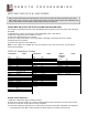
L I M I T E D W A R R A N T Y For Canadian model televisions, see separate sheets for Warranty/Garantie and JVC Authorized Service Centers in Canada. JVC COMPANY OF AMERICA warrants this product and all parts thereof, except as set forth below TO THE ORIGINAL PURCHASER AT RETAIL to be FREE FROM DEFECTIVE MATERIALS AND WORKMANSHIP from the date of original purchase for the period as shown below (the “Warranty Period”). The picture tube is covered for two years. Model No. Serial No.
AUTHORIZED SERVICE QUALITY C E N T E R S 23 SERVICE HOW TO LOCATE YOUR JVC SERVICE CENTER TOLL FREE: 1 (800) 537-5722 http://www.jvcservice.com Dear Customer; In order to receive the most satisfaction from your purchase, read the instruction booklet before operating the unit. In the event that repair is necessar y, or for the address nearest your location, please refer to the factory service center list below or within the Continental United States, call 1-800-537-5722 for your authorized servicer.
S P E C I F I C A T I O N S MODEL C-13010 C-13011 C-20010 AV-20020 AV-20021 NTSCSystem Reception format AV-27015 AV-27020 NTSC, BTSC System (Multi Channel Sound) VHF 2 to 13. UHF 14 to 69 Sub Mid, Super, Hyper and Ultra bands (181 channel frequency synthesizer system) Reception range Power consumption 60W / 1.1A 87W / 1.4A 87W / 1.4A Screen size 13 inch / 34 cm measured diagonally Audio output 1W 1W 1W x 2 1.