ENGLISH DEUTSCH FRANÇAIS MC-8200LU/MC-8600LU CD/DVD LIBRARY CD/DVD LIBRARY BEDIENUGSANLEITUNG : CD/DVD BIBLIOTHEK MANUEL D’INSTRUCTIONS : BIBLIOTHEQUE CD/DVD CD/DVD MC-8200LU MC-8600LU For Customer Use: Enter below the Model No. and Serial No. which is located on the rear of the cabinet. Retain this information for future reference. INSTRUCTIONS MC-8200LU MC-8600LU is a registered Trademark owned by Victor Company of Japan, Limited. Model No.
These are general IMPORTANT SAFEGUARDS and certain items may not apply to all appliances. 1. 2. 3. 4. 5. 6. 7. 8. 9. 10. 11. 12. 13. 14. 15. 16. 17. 18. 19. Read all of these instructions. Save these instructions for later use. All warnings on the product and in the operating instructions should be adhered to. Unplug this appliance system from the wall outlet before cleaning. Do not use liquid cleaners or aerosol cleaners. Use a damp cloth for cleaning.
For Europe For North America IMPORTANT The wires in this mains lead are coloured in accordance with the following code: GREEN - and - YELLOW: EARTH BLUE: NEUTRAL BROWN: LIVE As the colours of the wires in the mains lead of this apparatus may not correspond with the coloured markings identifying the terminals in your plug. proceed as follows.
Special Features The MC-8200LU/8600LU CD/DVD Library is a highly reliable and durable disc changer equipped with large capacity and high access speed to cope with the ever-changing needs of the rapidly developing information network age. This model is suitable for business as well as home use. • Six drive bay slots • Capacity Up to 600*1 optical discs*1 (12 cm discs) can be accomSix drive bay slots are provided so up to 6 drives*3 can modated. be installed.
CONTENTS 1. PRECAUTIONS ..................................................................................................................................................... 5 Installation and handling precautions ................................................................................................................. 5 Disc handling precautions .................................................................................................................................. 5 2.
1. PRECAUTIONS (1) Opening the transport lock • Make sure that the transport lock is released and all transport protective materials are removed before turning on the power. Failure to do so will result in equipment malfunction. (2) Location of installation • Do not install the equipment near a source of vibration such as motor, engine or loudspeaker. They may adversely affect the equipment performance. • Do not install the equipment in a place that is exposed to radiation, X-rays or corrosive gases.
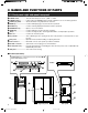
2. NAMES AND FUNCTIONS OF PARTS 2-1. Front panel, right side panel, rear panel 1 POWER switch ................... Turns the main unit power on/off. " | ":ON. " ":OFF. 2 POWER Indicator ............... Lights up when the POWER switch is turned on. Blinks in case of error during operation. 3 LCD Display Panel ............. Shows information using alphanumeric characters. 4 MODE key .......................... Used for LCD display page selection and other operations. 5 SELECT key .......................
Names and Functions of Parts 9 Mail slot .............................. Used for disc insertion/ejection. & Mail slot transport lock ..... Locks the mail slot during transport. * Magazines .......................... Each magazine contains 50 trays accommodating up to 50 discs. ( Drive bays .......................... Accommodation for up to 6 drive units is compatible with this product. The bays are numbered 1, 2, 3,4 5 and 6 from the bottom. ) Carrier ................................
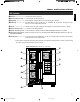
Names and Functions of Parts 2-3. Magazine numbers, tray numbers, disc numbers The internal layout of the magazine and the numbers assigned to the magazines, trays and discs are as shown below. Magazine number ...... This is the number assigned to each of the 4 or 12 sets of magazines. The error message displayed when a magazine is inserted incompletely refers to the magazine number. (See page E27) Note, magazine number assignments are different from previous models (MC-1000, MC-2000 and MC-7000 Series).
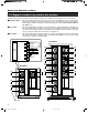
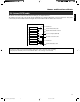
Names and Functions of Parts The SCSI connections inside the main unit (the Changer) are explained below: The SCSI board, drive units and an SE (single-ended)/LVC (Low Voltage Differential) conversion board are daisy-chain connected by an internal SCSI cable. The length of the internal SCSI cable should be about 1.0 meter.
3. SETUP The standard setup procedure is as shown below. Set up the equipment according to the procedure shown for each model. Start MC-8200LU MC-8600LU Attach the casters P.E10 Open the transport lock P.E11 Removing the transport protective materials P.E12 Mount the optional carrier *2 Install the drive units P.E22 Set the SCSI-ID numbers, etc. P.E23 Connect the power cord and cables P.E14 Execute the automatic drive detection mode. P.E24 Turn the power switch on. P.
Setup 1. ENGLISH 3-2. Opening the transport lock Open the door by inserting the key and turning it counterclockwise (90°) to unlock the door. Unlocked Door opening/closing key cylinder Locked 2. Open the transport lock of the mail slot. • Using a philps screwdriver, continue to turn the lock counterclockwise until the lock is completely disengaged and moves outwards. Lock pin 3. Open the transport lock of the carrier.
Setup 3-3. Removing the transport protective materials After opening the transport lock, proceed to the following steps without closing the door. 1. Remove magazine No. 1. (a See “9-1. Ejecting/loading the magazines” on page E27.) TO 2. P Pull out the protective material forwards. 3 4 2 Protective material 3. 4. Load magazine No. 1. (a See “9-1. Ejecting/loading the magazines” on page E27.) TO P Repeat the same operation for each of the remaining magazines.
Setup When the MC-CF10U is installed, its special transport lock should be removed in addition to its being unlocked as detailed in "3-2. Opening the transport lock" on page E11. Use the following procedure when unlocking the optional carrier transport lock. 1. Remove the transpor t lock screw (for optional carrier). 2. Insert the removed screw into the desigated storage hole for the transport lock screw. • If the system is transported with the MC-CF10U Optional Carrier installed, refer to "3-2.
Setup 3-6. Connecting the power cord and cables CAUTION Turn OFF the power of all equipment before starting connections. Connecting the equipment while power is ON may lead to a malfunction. To SCSI-C To the host adapter of computer To AC IN To AC outlet WARNING Always use the power cord provided by JVC. The library system has been designed to conform to “Insulation category Class 1”. In order to assure safety at all times, be sure to ground the system before use.
The switch operation and LCD display system has three operation and display modes as described below. Normal display ..... This mode includes two patterns, one of which is displayed automatically when the equipment starts up normally. The disc numbers in the drive units are displayed in real time. Menu display ........ This mode allows you to start user operations such as SCSI-ID No. checking and setting, internal history display and door/panel opening. Event display ........
Control Panel Operations and LCD Display 4-3. Event display 1 Power on P OW E R ON 2 During initialization When the MC-CF10U Optional Carrier is installed I N I T I A L I Z I NG 3 Error occurrence (a See “10-2. ERROR I N I T I A L I Z I NG F L I P CARR I ER Error code list” on page E31.) OCCURRED ! 4 During door opening (a See “5. Displayed alternately. Door Opening/Closing” on page E18.) THE E X E CU T I NG DOOR OP EN PROCE S S 5 When door is open (a See “5.
Control Panel Operations and LCD Display ENGLISH 4-4. Display and operation sequence The sequence of display and operation after turning the power on is as shown below. 1. NORMAL DISPLAY Power On SELECT ENTER POWER ON 2. ERROR DISPLAY Error display 1 SELECT INITIALIZING MODE Error display 2 Normal display SELECT SELECT SELECT SELECT Pattern 1 Error display 8 SELECT ENTER Pattern 2 3. ID No. DISPLAY SCSI-ID display SELECT ENTER SELECT 4. PANEL OPEN MODE PUSH SELECT SELECT 1.
5. DOOR OPENING/CLOSING Once the transport locks have been released and the power has been turned on for the first time, the door is locked by an internal safety lock in addition to the key so that the door cannot be opened with the key alone. In order to open the door with the key under these conditions, either maintain or turn on the power supply if it has not been turned on yet, and perform the following operations before inserting and turning the key. Door Opening 1.
6-1. Disc loading CAUTION Do not load or eject a disc before the mail slot has stopped completely. It may not only damage the disc but also cause the equipment to malfunction because of excessive force being applied during opening and closing. Disc loading/ejection method When a tray is transported to the mail slot under the control of the host computer or the import/export operation (a P. E20), the mail slot opens automatically when transportation has been completed. 1.
Mail Slot 6-2. Import/export operation When loading/ejecting discs from any chosen tray by the mail slot without the control of the host computer, follow the procedure shown below. • During the import/export operation, the host computer commands which include the carrier operations cannnot be executed. 1. 2. In the normal display mode, press the MODE key. (The menu display appears.) 1 . NORMA L D I S P L A Y 2 . ERROR D I S P L A Y Press the SELECT key 7 times. ("8. IMPORT/EXPORT" appears.) 8 .
10. When the mail slot automatically opens, place the desired disc on the tray (number is displayed on the LCD). (a See "6-1. Disc loading" on page E19.) •To remove a disc, lift it out of the tray. •When the following message appears on the LCD display, it is possible that the transport lock of the mail slot has not been properly released. Please make sure that that lock pin has been removed completely. (a See "3-2. Opening the transport lock" on page E11.
7. DRIVE UNITS CAUTION • Make sure that the power is turned off when installing/removing, connecting or setting a drives. Performing these operations while the power is on will result in the equipment malfunctioning. Be sure to read the instruction manuals of the drive units before proceeding to any of the following work. • Note that certain device drivers are incompatible with the simultaneous use of more than one type of drive (mixed use). Please consult your dealer or nearest JVC service center. 7-1.
Drive Units s Procedure for setting the SCSI-ID No. and other jumper settings. Please refer to the specified section(s) of the corresponding drive instruction manual. s Make sure to turn the power OFF before starting the procedure. If the procedure is carried out with the power ON, it will cause malfunction. s The new ID Nos. will become effective from the the moment the power is turned on. s The new SCSI ID Nos. should not conflict with the ID Nos. of other SCSI equipment on the same SCSI bus.
Drive Units 7-5. Installing the panels CAUTION s Check the installation screws and cables before installing the panel. Insufficient connections may cause malfunctions. 1. Attach rear and side panels. • Screw the panels on, following the procedure in "7-1 Removing the panel" on page E22 in the reverse order. 2. Close the door (a See "5. Door Opening/Closing" on page E18.) 7-6.
Drive Units Check the types of the installed drives as follows. 1. Press the MODE key while the LCD display is in normal display mode (to display Menu display). 2. Press the SELECT key 8 times (to display "9. DRIVE DISPLAY"). 3. Press the ENTER key (to select "9. DRIVE DISPLAY"). 4. The type of the drive in each drive bay will be displayed. (Each press of the SELECT key displays the information on the next drive.) 1 . NORMA L D I S P L A Y 2 . ERROR D I S P L A Y 9 . DR I VE D I SP L AY 1 .
8. SETTING THE SCSI-ID NUMBERS OF THE MAIN UNIT Perform the following operations when changing the setting of the SCSI-ID Nos. of the main unit (changer). 1. In the normal display mode, press the MODE switch. (the menu display returns.) 1 . NORMA L D I S P L A Y 2 . ERROR D I S P L A Y 2. Press the SELECT key 5 times. ("6. ID No. SET MODE" appears.) 6 . I D N o . S E T MOD E 7 . COUN T D I S P L A Y 3. Press the ENTER key. (Select and enter "6. ID No. SET MODE".) PUSH SELECT KEY TO CHANGE I D No .
CAUTION • Do not use a magazine which has been damaged (e.g. dropped), as normal operation cannot be accomplished with such a magazine. In addition, the use of such a magazine may damage the internal mechanism. • The magazines and trays used with the MC-1000/2000 series CD-ROM Library and MC-7000 series DVD-RAM Library are not compatible with those used with the MC-8000 series CD/DVD Library. Do not interchange the magazines and trays between these models, as this will damage the equipment.
Magazines 9-2. Loading/replacing the discs CAUTION • When loading discs directly into the magazine trays without using the mail slot, be careful not to damage the magazines and trays. • A disc may become impossible to write/read due to dust, fingerprints, scratches, etc. adhering to the disc surface. Please handle it carefully. • Take special care in handling the DVD-RAM discs because they are extremely vulnerable to scratches and contamination.
Magazines If a magazine was removed and reinstalled after the power had been turned on, this function will automatically check the disc status inside the magazine. Checking the operation modes. Press and hold the MODE switch for more than 5 seconds. • The factory default setting for the automatic disc checking function is on.
10. ERROR CODES In the event an error, the control panel indicator blinks and the LCD shows the error details by overriding any other information. MODE LOAD/EJECT SELECT POWER MAIL SLOT The indicator blinks. 10-1. Error code explanation LCD displays in the event of error ERROR OCCURRED ! DISC = 124 If the transport lock of the carrier has not been opened, this section shows "CHECK CAR. SCREW". Disc No.
Error Codes Device Device part C U C L C C C D F M E L T T (D#)*1 C E D S Error code 01 02 03 04 07 08 09 10 11 12 20 21 22 23 24 25 26 27 28 29 30 31*2 32 41 42 43 80 81 50 51 52 60 61 62 63 64 65 ENGLISH 10-2.
Error Codes 10-4. Error history display The history of past errors can be displayed as described below. 1. In the normal display mode, press the MODE key. (The menu display appears.) 2. Press the SELECT key once. ("2. ERROR DISPLAY” appears.) 3. Press the ENTER key. (Select “2. ERROR DISPLAY".) "NO ERROR FOUND” appears if no error has occurred in the past. If there is any past error, the data on the latest 8 error occurrences can be recalled from memory and displayed. 4.
Access counts of the main unit (changer) and each unit (carrier, drives 1 - 6 and color disc printer) can be checked using this function. 1. In the normal display mode, press the MODE switch. (The menu display appears.) 2. Press the SELECT key 6 times. ("7. COUNT DISPLAY" appears.) 3. Press the ENTER key. (Select "7. COUNT DISPLAY".) 4. Pressing the SELECT key changes the display. ( 1. TOTAL : The total access count for the Library. 2. CR : Carrier 3. MS : Mail slot 4. DR1 : Drive 1 5.
SPECIFICATIONS Item Number of stored discs Number of magazines Operating environment Rated power voltage Rated power frequency Rated current Power consumption Interface Drive slots rack bays Media size Applicable Drives options Carrier Magazine Weight MC-8200LU MC-8600LU 200 600 4 12 Temperature: 5°C to 35°C (41°F to 95°F) (Note 1) Humidity: 10% to 80% (no condensation) AC 120 V to 240 V 50 Hz/60 Hz 3.2 A to 1.8 A (max. value), 1.4 A to 0.8 A (6 Drives are loaded) 2.4 A to 1.4 A (max. value), 1.
DEUTSCH CD/DVD-BIBLIOTHEK MC-8200LU MC-8600LU BEDIENUNGSANLEITUNG G1 MC-8200LU_8600LU INST(G) 1 04.10.
ERLÄUTERUNG DER AUFKLEBER KLASSENSCHILD AUF GEHÄUSERÜCKSEITE. CLASS LASER WARNUNG–DIESES GERÄT MUSS GEERDET WERDEN. DER 1 PRODUCT ACHTUNG: SCHÜTZEN SIE DIESES GERÄT VOR NÄSSE UND FEUCHTIGKEIT, DAMIT ES NICHT IN BRAND GERÄT UND KEIN KURZSCHLUSS ENTSTEHT. WARNUNG Hinweis: (1) Der Klassifizierungsaufkleber befindet sich auf der Geräterückseite. Dies ist ein Klasse-A-Produkt. In einer Wohngegend kann dieses Gerät Störungen verursachen, die der Bediener auf eigene Kosten beheben muss.
Vielen Dank für den Erwerb einer CD/DVD-Bibliothek MC-8200LU/MC-8600LU von JVC. • Kapazität Bis zu 600*1 optische Discs*2 (12 cm Discs) können untergebracht werden. • Sechs Laufwerkfächerschlitze Es sind vier Laufwerkfächerschlitze für die Installierung von bis zu 6 Laufwerken*3 vorhanden. • Kompatibel mit zweiseitigen Discs. Durch Hinzufügung eines optionalen Trägers*4 können zweiseitige Discs ebenfalls verwendet werden.
INHALTSVERZEICHNIS 1.VORSICHTSMASSNAHMEN ..................................................................................................................................... 5 Hinweise zum Aufbau und zur Handhabung ...................................................................................................... 5 Vorsichtshinweise beim Umgang mit Discs ........................................................................................................ 5 2. BEZEICHNUNG UND FUNKTION DER TEILE ..
1. VORSICHTSMASSNAHMEN (1) Lösen der Transportsicherung • Vergewissern Sie sich vor Einschalten des Geräts, daß die Transportsicherungen gelöst und alle Schutzverkleidungen entfernt wurden. Andernfalls müssen Sie mit Fehlfunktionen des Geräts rechnen. (2) Aufstellung des Geräts • Stellen Sie das Gerät nicht in der Nähe von Vibrationsquellen wie z.B. Motoren, Antrieben oder Lautsprechern auf. Die Funktion des Geräts kann dadurch beeinträchtigt werden.
2. BEZEICHNUNG UND FUNKTION DER TEILE 2-1. Frontplatte, rechte Seitenwand und Rückseite 1 Netzschalter (POWER) ...... Schaltet die Spannungsversorgung der Haupteinheit ein/aus. " | ": Ein, " ": Aus 2 Betriebsanzeige ................. Leuchtet auf, wenn der Netzschalter (POWER) eingeschaltet ist. Blinkt bei Fehlern während des Betriebs. 3 LCD-Anzeige ...................... Zeigt mit alphanumerischen Zeichen Informationen an. 4 Taste MODE .......................
Bezeichnung und Funktion der Teile 2-2. Innenansicht 9 Einlegeschublade .............. Zum Einlegen/Entnehmen der Discs. & Transportverriegelung der * Magazin .............................. Jedes Magazin enthält 50 Träger und kann so bis zu 50 Discs aufnehmen. ( Laufwerkseinschübe ......... Für dieses Produkt sind bis zu 6 Laufwerke möglich. Die Einschübe sind von unten nach oben mit 1, 2, 3, 4, 5 und 6 durchnumeriert. ) Transportvorrichtung ........
Bezeichnung und Funktion der Teile 2-3. Magazinnummern, Trägernummern, Disc-Nummern Die interne Aufteilung eines Magazins und die Nummern, die den Magazinen, Trägern und Discs zugeordnet sind, sind in der Abbildung unten dargestellt. Magazinnummer: ....... Nummer, die die 4 bzw. 12 eingesetzten Magazine bezeichnet. Fehlernachrichten bei nicht richtig eingelegten Magazinen beziehen sich auf die Magazinnummer. ( a Seite G27) Trägernummer: ..........
Bezeichnung und Funktion der Teile 2-4. Internes SCSI-Kabel Die SCSI-Anschlüsse im Gerät (Disc-Wechsler) werden weiter unten erläutert: Die SCSI-Karte, die Laufwerke und die SE/LVD-Karte (Single-ended/Low Voltage Differential) sind geräteintern mittels eines SCSI-Kabels in Reihe geschaltet. Die Länge des internen SCSI-Kabels sollte ca. 1,0 m betragen. Laufwerk 6 DEUTSCH Innenansicht Terminator Internes SCSI (LVD)-Kabel Laufwerk 5 externer 68-pol.
3. INBETRIEBNAHME Die Standard-Prozedur für die Inbetriebnahme ist nachfolgend dargestellt. Stellen Sie das Gerät entsprechend dem Modelltyp ein. Start MC-8200LU MC-8600LU Laufrollen anbringen Seite G10 Transportverriegelung lösen Seite G11 Transportschutzmaterial entfernen Seite G12 Anbringung des wahlweisne Wechselrobotiks. *2 Laufwerke einbauen Seite G22 Ersteinstellung von SCSI-ID-Nr. usw.
Inbetriebnahme 3-2. Transportverriegelung lösen 1. Schließen Sie die Tür auf, indem Sie den Schlüssel 90° gegen den Uhrzeigersinn drehen. DEUTSCH Öffnen Zylinderschlüssel zum Öffnen/Schließen der Tür Schließen 2. Lösen Sie die Transportverriegelung der Einlegeschublade. • Drehen Sie die Verriegelung mit einem KreuzschlitzSchraubendreher gegen den Uhrzeigersinn; der Sicherungsstift ist dann gelöst. Sicherungsstift 3. Lösen Sie die Transportverriegelung der Transportvorrichtung.
Inbetriebnahme 3-3. Transportschutzmaterial entfernen Lassen Sie nach dem Lösen der Transportverriegelungen die Tür geöffnet. 1. Nehmen Sie Magazin Nr. 1 heraus. (a Siehe “9-1. Magazine entnehmen/einsetzen” auf Seite G27.) TO 2. P Ziehen Sie das Schutzmaterial heraus. 3 4 2 Schutzmaterial 3. Setzen Sie das Magazin Nr. 1 ein. (a Siehe “9-1. Magazine entnehmen/einsetzen” auf Seite G27.) 4. Das Kabel an der Seite des Laufwerkschachts am Laufwerk anschließen.
Inbetriebnahme 3-4. Entfernung der Transportverriegelungschraube des wahlweisen Wechselrobotiks 1. Die Transportverriegelungschraube entfernen (für wahlweisen Wechselrobotik). 2. Die entfernete Schraube im Aufbewahrungsloch für die Transport-verriegelungschraube einsetzen. DEUTSCH Wenn der MC-CF10U installiert ist, sollte dessen spezielle Transportverriegelung nicht nur entriegelt sondern ebenfalls entsprechend "3-2. Transpotverriegelung lösen" auf Seite G11 entfernt werden.
Inbetriebnahme 3-6. Netzkabel und andere Kabel anschließen ACHTUNG Sämtliche Geräte ausschalten, bevor Sie ein Kabel anschließen oder entfernen. Herstellen oder Lösen von Kabelverbindungen zwischen eingeschalteten Geräten kann zu Funktionsstörungen führen. Zum SCSI-A An den Hostadapter eines computers Zum Netzanschluß Zur Netzsteckdose WARNUNG Immer das von JVC mitgelieferte Netzkabel verwenden. Das Bibliothek-System entspricht der "Isolationsklasse 1".
4. BEDIENKONSOLE UND LCD-ANZEIGE 4-1. Normalmodus Anzeigemuster 1 wird automatisch angezeigt, wenn der Start normal verlaufen ist. Das Anzeigemuster kann mit der Taste SELECT weitergeschaltet werden. [Anzeigemuster 1] Transportvorrichtung leer Einlegeschublade CR : – – – D1 : 0 3 6 MS : – – – D2 : 0 7 5 Laufwerk 1 Laufwerk 2 Disc-Nr. SELECT [Anzeigemuster 2] SELECT Nicht angeschlossen D3 : NC D5 : NC Laufwerk 3 Laufwerk 5 D 4 : NC D 6 : NC Laufwerk 4 Laufwerk 6 4-2.
Bedienkonsole und LCD-Anzeige 4-3. Ereignismodus 1 Einschalten P OW E R ON 2 Initialisierung läuft Wenn der wahlweise MC-CF10U Wechselrobotik installiert ist. I N I T I A L I Z I NG 3 Fehler (a Siehe “10-2. ERROR I N I T I A L I Z I NG F L I P CARR I ER Fehlercodeliste” auf Seite G31.) OCCURRED ! 4 Beim Öffnen der Tür (a Siehe “5. Abwechselnd angezeigt. D I SC= 1 2 4 CODE = CU 0 4 Tür öffnen/schließen” auf Seite G18.
Bedienkonsole und LCD-Anzeige 4-4. Anzeige und Bedienungsablauf Der Ablauf von Anzeige und Bedienung nach dem Einschalten ist nachfolgend abgebildet. 1. NORMAL DISPLAY Einschalten SELECT ENTER 2. ERROR DISPLAY Fehleranzeige 1 DEUTSCH POWER ON SELECT INITIALIZING MODE Fehleranzeige 2 Normalmodus SELECT SELECT SELECT SELECT Anzeigemuster 1 Fehleranzeige 8 SELECT ENTER Anzeigemuster 2 3. ID No. DISPLAY SCSI-ID Anzeige SELECT ENTER SELECT 4. PANEL OPEN MODE PUSH SELECT... SELECT 1.
5. TÜR ÖFFNEN/SCHLIESSEN Wenn die Transportverriegelung gelöst und das Gerät zum ersten Mal eingeschaltet wurde, ist die Tür zusätzlich mit einem internen Sicherheitsschloß gesichert, so daß sie nicht mit dem Schlüssel allein geöffnet werden kann. Um unter diesen Umständen die Tür zu öffnen, müssen Sie das Gerät einschalten oder eingeschaltet lassen und wie folgt vorgehen, bevor Sie den Schlüssel einstecken und umdrehen: Tür öffnen 1. Drücken Sie im Normalmodus die Taste MODE.
6. EINLEGESCHUBLADE 6-1. Disc einlegen Disc einlegen/entnehmen Wenn eine Ablage durch Hauptrechnersteuerung oder Import/Export-Operation (a S.G20) zum Postschlitz transportiert wird, öffnet sich der Postschlitz nach Transportbeendigung automatisch. 1. Legen Sie eine Disc vorsichtig mit der Label-Seite nach oben zu bedruckenden Oberfläche nach oben auf den Träger. (Halten Sie die Disc zur Entnahme an der Mittelöffnung sowie am Rand auf der Höhe der Einbuchtung vorne am Träger.
Einlegeschublade 6-1. Disc einlegen von Discs 6-2. Import/Export Um Discs eines beliebigen Trägers ohne Ansteuerung durch den Steuercomputer zu laden oder auszuwerfen, verfahren Sie wie folgt. • Während der Durchführung von Import oder Export können keine Befehle des Steuerungscomputers (einschließlich Transportoperationen) durchgeführt werden. 1. Drücken Sie im Normalmodus die Taste MODE. (Die Menüanzeige erscheint.) 2. Drücken Sie die Taste SELECT siebenmal. (“8. IMPORT/EXPORT” erscheint.) 3.
Einlegeschublade Die Einlegeschublade öffnet sich automatisch. Die Nummer des gerade bearbeiteten Trägers erscheint auf der LCDAnzeige. Legen Sie die gewünschte Disk auf den Träger. (a Siehe “6-1. Disk einlegen” auf Seite G19.) •Um eine Disk zu entfernen, entnehmen Sie sie aus dem Träger. •Wenn die folgende Nachricht auf der LCD-Anzeige erscheint, kann es sein, daß die Transportverriegelung der Einlegeschublade nicht richtig gelöst wurde. Prüfen Sie, ob der Sicherungsstift vollständig entfernt wurde.
7. LAUFWERKE ACHTUNG • Vergewissern Sie sich, daß vor dem Installieren/Herausnehmen, Anschließen oder Einstellen eines als Sonderausstattung Laufwerks die Stromversorgung ausgeschaltet ist. Das Ausführen dieser Arbeiten bei eingeschaltetem Gerät kann zu Fehlern führen. Für Ausführung folgender Arbeitsschritte erst die Bedienungsanleitungen der Laufwerke durchlesen.
Laufwerke s Die SCSI ID-Nr. für das Laufwerk usw. eingeben. Für die zur Eingabe erforderlichen Schritte sich auf die Bedienungsanleitung des als Sonderausstattung erhältlichen Laufwerks beziehen. s Vergewissern Sie sich, daß das Gerät ausgeschaltet ist, bevor Sie mit den Einstellungen beginnen. Eine Änderung der Einstellungen bei eingeschaltetem Gerät führt zu Störungen und Fehlfunktionen. s Die neu eingestellten ID-Nummern werden beim nächsten Einschalten des Geräts wirksam.
Laufwerke 7-5. Abdeckungen einbauen s Überprüfen Sie den Sitz der Schrauben und der Kabelverbindungen, bevor Sie die Abdeckungen einbauen. Mangelhafter Kontakt kann zu Fehlfunktionen führen. 1. Bringen Sie die Seiten- und Rückwand wieder an. • Schrauben Sie die Abdeckungen fest. Führen Sie dazu “7-1. Abdeckung entfernen” von Seite G21 in umgekehrter Reihenfolge aus. 2. Schließen Sie die Tür (a Siehe “5. Tür öffnen/schließen” auf Seite G18.) 7-6.
Laufwerke 7-7. Laufwerktypanzeige Überprüfen Sie die jeweilige Laufwerksausführung wie folgt.. Bei normalen Anzeigenbetrieb der LCD-Anzeige die MODE-Taste betätigen (für Einstellung der Menüanzeige). 2. Die SELECT-Taste 8mal betätigen (für Anzeige von "9. DRIVE DISPLAY"). 3. Die ENTER-Taste betätigen (für Einstellung von "9. DRIVE DISPLAY"). 4. Der Laufwerktyp in jedem Laufwerkfach wird angezeigt. (Jedesmal bei Betätigung der SELECT-Taste, werden Informationen über das nächste Laufwerk angezeigt.
8. EINSTELLEN DER SCSI-ID-NUMMERN DER HAUPTEINHEIT Führen Sie zum Ändern der SCSI-ID-Nummern der Haupteinheit (Wechsler) die folgenden Schritte durch: 1. Drücken Sie im Normalmodus die Taste MODE. (Die Menuanzeige erscheint.) 2. Drücken Sie die Taste SELECT fünfmal. ("6. ID No. SET MODE" erscheint.) 3. 4. 1 . NORMA L D I S P L A Y 2 . ERROR D I S P L A Y 6 . I D N o . S E T MOD E 7 . COUN T D I S P L A Y Drücken Sie die Taste ENTER. (Bestätigen Sie die Auswahl "6. ID No. SET MODE".
9. MAGAZINE DEUTSCH ACHTUNG • Verwenden Sie kein Magazin, das durch Fall oder andere Einflüsse beschädigt wurde; mit solchen Magazinen ist kein normaler Betrieb möglich. Außerdem kann die Verwendung fehlerhafter Magazine den internen Mechanismus beschädigen. • Die Magazine und Ablagen der MC-1000/2000 Serie der CD-ROM-Bibliothek und der MC-7000 Serie der DVD-RAMBibliothek sind nicht kompatibel mit denen, die für die MC-8000 Serie verwendet werden.
Magazine 9-2. Discs einlegen/wechseln ACHTUNG • Wenn Discs nicht über die Einlegeschublade, sondern direkt in die Magazinträger eingelegt werden, achten Sie darauf die Magazine und Träger nicht zu beschädigen. • Durch Kratzer, Staub, Fingerabdrücke und andere Oberflächenverschmutzungen kann das Lesen/Beschreiben einer Disc unmöglich werden. Behandeln Sie Discs stets mit größter Sorgfalt. • DVD-RAM Discs sollten besonders behandelt werden, da diese sehr anfällig für Kratzer und Schmutz sind.
Magazine 9-3. Automatische Discs-Testfunktion Wenn ein Magazin entfernt und nach Einschalten des Geräts wieder eingesetzt wurde, wird der Disc-Bestand in diesem Magazin automatisch überprüft. Automatische Discs-Testfunktion EIN AUTO D I SC ON CHECK : DEUTSCH Feststellen der Betriebsart Drücken und halten Sie die Taste MODE für mindestens fünf Sekunden. • Ab Werk ist die automatische Discs-Testfunktion eingeschaltet.
10. FEHLERCODES Im Falle eines Fehlers blinkt die Betriebsanzeige an der Vorderseite, und in der LCD-Anzeige wird der Fehler angezeigt; andere Informationen werden überschrieben. MODE SELECT LOAD/EJECT POWER MAIL SLOT Die Betriebsanzeige blinkt. 10-1. Erläuterung der Fehlercodes LCD-Anzeige bei einem Fehler ERROR OCCURRED ! DISC = 124 Wenn die Transportverriegelung derTransportvorrichtung nicht gelöst wurde, erscheint die Anzeige CHECK CAR. SCREW. Disc Nr.
Fehlercode 10-2. Fehlercodeliste Einzelheit der Einheit C U C L C C Fehler code 01 02 03 04 07 08 09 10 11 12 20 21 22 23 24 25 26 27 28 29 30 31*2 32 41 42 43 80 81 50 51 52 60 61 62 63 64 65 D C F M E L T T D#*1 C E D S Fehlerhafte Funktion Der Drehsensor (auf/ab) spricht nicht an. Der linke Sensor spricht nicht an. Der rechte Sensor spricht nicht an. Der Auf/Ab-Motor funktioniert nicht. (Die Transportverriegelung der Transportvorrichtung ist möglicherweise nicht gelöst.
Fehlercodes 10-4. Anzeige des Fehlerprotokolls Eine Protokollierung früher aufgetretener Fehler läßt sich wie folgt anzeigen. 1. Drücken Sie im Normalanzeigemodus die Taste MODE. (Die Menüanzeige erscheint.) 2. Drücken Sie die Taste SELECT einmal. (“2. ERROR DISPLAY” wird angezeigt.) 3. Drücken Sie die Taste ENTER. (Bestätigen Sie die Auswahl “2. ERROR DISPLAY”.) “NO ERROR FOUND” wird angezeigt, wenn in der Vergangenheit keine Fehler aufgetreten sind.
11. ZUGRIFFSZÄHLER Die Zugriffszähler für die Haupteinheit (Wechsler) und für jede Untereinheit (Transportvorrichtung, Laufwerke 1-6 und Beschriftungsdrucker) können wie folgt abgelesen werden. Drücken Sie im Normalmodus die Taste MODE. (Die Menüanzeige erscheint.) 2. Drücken Sie die Taste SELECT sechsmal. (“7. COUNT DISPLAY” erscheint.) 3. Drücken Sie die Taste ENTER. (“Bestätigen Sie die Auswahl “7. COUNT DISPLAY”.) 4. Ein Druck auf die Taste SELECT ändert die Anzeige. ( 1.
TECHNISCHE DATEN MC-8200LU Gerät Anzahl gespeicherter Discs Anzahl Magazine Klimabedingungen Netzspannung Netzfrequenz Stromaufnahme Leistungsaufnahme Schnittstelle Laufwerkeinschübe Datenträgergröße AnwendbareOptionen Laufwerke MC-8600LU 200 600 4 12 Temperatur: 5 °C bis 35 °C (Hinweis 1) Relative Luftfeuchte: 10 % bis 80 % (ohne Kondensation) 120 V bis 240 V AC 50 Hz/60 Hz 2,4 A bis 1,4 A (max.), 1,4 A bis 0,8 A (6 eingesetzte Laufwerke) 3,2 A bis 1,8 A (max.
FRANÇAIS BIBLIOTHEQUE CD/DVD MC-8200LU MC-8600LU MANUEL D’INSTRUCTIONS F1 MC-8200U_8600U INST(F) 1 04.10.
REPRODUCTION DES ETIQUETTES 1. ETIQUETTE DE CLASSIFICATION, SUR L'ARRIERE DU COFFRET. CLASS LASER 1 PRODUCT Remarque: (1) Le label de classification est placé sur le panneau arrière. AVERTISSEMENT–CET APPAREIL DOIT ETRE MIS A LA TERRE. AVERTISSEMENT : POUR ÉVITER LES RISQUES D’INCENDIE OU D’ÉLECTROCUTION, NE PAS EXPOSER L’APPAREIL À LA PLUIE NI À L’HUMIDITÉ. Information for Canada This Class [A] digital apparatus complies with Canadian ICES-003.
Nous vous remercions d’avoir fait l’acquisition d’une bibliothèque CD/DVD JVC MC-8200LU et MC-8600LU. Particularités La bibliothèque CD/DVD MC-8200LU, MC-8600LU est un changeur de disques de haute fiabilité, grande capacité et vitesse d’accès élevée destiné à répondre aux besoins évolutifs de l’ère informatique. Ce modèle convient tant pour les applications professionnelles que privées. • Six logements baies pour unité lecteur Ces quatre logements baies permettent l'installation de 6 unités lecteurs*3.
SOMMAIRE 1. CONSIGNES .......................................................................................................................................................... 5 Conseils d’installation et de manipulation ........................................................................................................... 5 Précautions à prendre pour manipuler les disques ............................................................................................. 5 2.
1. CONSIGNES Conseils d’installation et de manipulation (2) Lieu d’installation • N’installez pas l’appareil à proximité d’une source de vibration comme un moteur ou un haut-parleur susceptible de perturber ses performances. • N’installez pas l’équipement à un emplacement exposé aux radiations, aux rayons X ou à des gaz corrosifs. Cela pourrait provoquer un mauvais fonctionnement ou une défaillance de l’équipement.
2. NOMENCLATURE ET FONCTION DES COMPOSANTS 2-1. Panneau avant, côté droit, Panneau arrière 1 Interrupteur POWER ...................... Sert à la mise sous tension et hors tension de l'appareil . "I": marche; "O": arrêt. 2 Témoin ............................................ S'allume lorsque l'interrupteur POWER est sur MARCHE. Clignote s'il y a une erreur pendant le fonctionnement. Affichage LCD ................................ Indique les informations sous forme alphanumérique. 3 4 Touche MODE .............
Nomenclature et fonction des composants 2-2. Intérieur 9 Alvéole rectangulaire ............................. Sert à l’insertion/éjection des disques. & Verrouillage de transport du chargeur frontal ................................ Bloque l’alvéole pendant le transport. * Magasin ................................................... Chaque magasin contient 50 plateaux qui accueillent 50 disques. ( Emplacements pour les unités ............. Accepte un maximum de 4 unités lecteurs.
Nomenclature et fonction des composants 2-3. Numéros des magasins, des plateaux et des disques La disposition interne de chaque magasin et les numéros attribués aux magasins, plateaux et disques sont indiqués ci-dessous. Numéro de magasin .. Il s’agit du numéro attribué à chacun des 4 ou 12 jeux de magasins. Le message d’erreur qui s’affiche lorsque un magasin est incomplètement introduit se rapporte au numéro de ce magasin. 'a Voir page F27) Numéro de plateau ....
Nomenclature et fonction des composants 2-4. Câble SCSI interne Les connexions SCSI à l’intérieur de l’unité principale (changeur) sont expliquées ci-dessous. La carte SCS, les unités et une carte de conversion SE (simple)/LVC (différentiel basse tension) sont raccordées en guirlande par un câble SCSI intérieur. La longueur de ce câble SCSI intérieur est d’environ 1,0 mètres. Inutilisé.
3. INSTALLATION La procédure standard d'installation est indiquée ci-dessous. Installez les équipements en fonction. Début MC-8200LU MC-8600LU Pose des pattes à roulettes Page F10 Déblocage du verrouillage de transport Page F11 Dépose des éléments de protection de transport Page F12 Monter le chariot en option **2 Installation des lecteurs Page F22 Détermination initiale des numéros d'identification SCSI, etc.
Installation 3-2. Déblocage du verrouillage de transport 1. Ouvrez la porte en tournant la clé dans le sens anti-horaire (90°) pour la débloquer. Déverrouillé 2. Serrure d’ouverture/fermeture de la porte FRANÇAIS Verrouillé Débloquez le verrouillage de transport du chargeur frontal. • A l’aide d’un tournevis,dé vissez (dans le sens antihoraire) pour faire sortir l’ergot. Ergot 3. Débloquez le verrouillage de transport du changeur.
Installation 3-3. Dépose des éléments de protection de transport Après avoir débloqué le verrouillage de transport, effectuez ce qui suit sans fermer la porte. 1. Sortez le magasin n° 1. (➨ Voir “9-1. Ejection/chargement des magasins” à la page F27.) TO P 2. Tirez les éléments de protection vers l’avant. 3 4 2 Eléments de protection 3. Chargez le magasin n° 1. (➨ Voir “9-1. Ejection/chargement des magasins” à la page F27.) TO P 4.
Installation 3-4. Retrait de la vis de verrouillage du chariot en option Quand le MC-CF10U est installé, sa vis de verrouillage doit être retirée en plus de son déverrouillage comme indiqué dans "3-2. Déblocage du verrouillage de transport" à la page F11. Procédez comme suit pour le déverrouillage du verrou de transport du chariot en option. Retirez la vis de verrouillage de transport (pour le chariot en option). 2. Vissez la vis retirée dans le trou de rangement dé dié . FRANÇAIS 1.
Installation 3-6. Branchement du cordon secteur et des câbles ATTENTION Vérifiez que tout l’équipement soit en position arrêt avant d’entamer les branchements. Toute connexion à la bibliothèeque alors qu'elle est sous tension peut perturber son fonctionnement. Vers SCSI-A Vers l’adaptateur hôte d’un ordinateur Vers entrée secteur Vers secteur de sortie AVERTISSEMENT N'utilisez que le cordon secteur fourni par JVC.
4. PANNEAU DE COMMANDE ET AFFICHAGE LCD Les touches et l'affichage LCD présentent trois fonctions et modes d’affichage comme indiqué ci-dessous : Affichage normal ................... Ce mode compte deux écrans dont l'un est affiché automatiquement lorsque l'appareil est enclenché normalement. Les numéros des disques présents dans les unités sont affichés en temps réel. Affichage menu .....................
Panneau de commande et affichage LCD 4-3. Affichage des événements 1 Mise sous tension P OW E R ON 2 Pendant l’initialisation Quand le chariot MC-CF10U en option est installé. I N I T I A L I Z I NG I N I T I A L I Z I NG F L I P CARR I ER 3 Apparition d’erreurs (a Voir “10-2. Liste des codes d’erreurs” à la page F31.) ERROR OCCURRED ! Affichés en alternance. D I SC= 1 2 4 CODE = CU 0 4 4 Pendant l’ouverture de la porte (a Voir “5. Ouverture/fermeture de la porte” à la page F18.
Panneau de commande et affichage LCD 4-4. Affichage et succession des opérations La succession de l’affichage et des opérations après avoir mis l’appareil sous tension est indiquée ci-dessous. 1. NORMAL DISPLAY Mise sous tension SELECT ENTER POWER ON 2. ERROR DISPLAY Affichage d'erreur 1 SELECT INITIALIZING MODE Affichage d'erreur 2 Affichage normal SELECT Affichage d'erreur 8 FRANÇAIS SELECT SELECT SELECT Affichage 1 SELECT Affichage 2 ENTER 3. ID No.
5. OUVERTURE/FERMETURE DE LA PORTE Après déblocage du verrouillage du transport et première mise sous tension, il subsiste un verrouillage supplémentaire de la porte. La clé mécanique ne suffit donc pas à l'ouvrir. Pour ouvrir la porte avec la clé dans ces conditions, mettez ou laissez l'appareil sous tension et effectuez les opérations suivantes avant d'introduire et de tourner la clé. Ouverture de la porte 1. Sous l'affichage normal, appuyez sur MODE. (L'affichage menu apparaît.) 2.
6. CHARGEUR FRONTAL 6-1. Chargement d'un disque ATTENTION Ne chargez ni n'éjectez de disque avant l'arrêt complet du chargeur frontal. Non seulement le disque risquerait d'être endommagé, mais l'équipement pourrait aussi tomber en panne en raison de la force excessive appliquée pendant l'ouverture et la fermeture. 1. Placez un disque avec précaution sur le plateau, étiquette vers le haut.
Chargeur frontal 6-2. Opération d'importation/exportation Pour le chargement/éjection de disque de l'un des plateaux par le chargeur frontal, sans commande de l'ordinateur, suivez la procédure indiquée ci-dessous. • Pendant l'opération d'importation/exportation, les commandes de l'ordinateur qui contrô lent les opérations du chariot ne peuvent pas être exécutées. 1. 2. En affichage normal, appuyez sur MODE. (Le menu apparaît.) 1 . NORMA L D I S P L A Y 2 .
Chargeur frontal 10. Lorsque le chargeur s'ouvre , posez un disque sur le plateau (son nombre apparaît à l'affichage LCD). (a Voir "6-1. Chargement d'un disque" à la page F19.) • Pour enlever un disque, soulevez-le du plateau. • Lorsque le message suivant apparaît à l’affichage LCD, il se peut que le verrouillage de transport de l’alvéole rectagulaire ne soit pas correctement débloqué. Vérifiez que ce verrouillage soit complètement enlevé. (a Voir "3-2.
7. UNITES LECTEURS ATTENTION • Vérifier que l’appareil est hors lors de l'installation/dé sinstallation, au raccordement ou au réglage d’un lecteur. Si ces opérations sont effectuées sous tension, le fonctionnement de l'appareil en sera perturbé. Lisez bien le mode d'emploi des unités lecteurs avant d'effectuer l'une des opérations suivantes. • Notez que certaines unités lecteurs sont incompatibles avec l'emploi simultané de plus d'un type de lecteur (utilisation combinée).
Unités lecteurs 7-3. Détermination des numéros d’identification SCSI, etc. s Régler le numé ro d'identification SCSI du lecteur. Consulter le mode d'emploi du lecteur pour les procédures de réglage. s N’oubliez pas de couper l’alimentation avant d’entamer la procédure. Si la procédure est effectuée avec l’alimentation enclenchée, il y a risque de perturbation. s Les numéros d’identification SCSI déterminés ne deviennent effectifs qu’après la prochaine mise sous tension.
Unités lecteurs 7-5. Pose des panneaux sVérifiez les connexions de l'installation, les vis et les câbles avant de poser le panneau. Les connexions douteuses conduisent à des erreurs de fonctionnement. 1. Posez les panneaux arrière et latéral. • Vissez les panneaux en inversant la procédure de “7-1 Dépose des panneaux” à la page F21. 2. Fermez la porte. (a Voir "5. Ouverture/fermeture de la porte" à la page F18.) 7-6.
Unités lecteurs 7-7. Affichage du type de lecteur Vérifiez le type des unités installées comme suit. Appuyez sur la touche MODE avec l'affichage LCD en mode d'affichage normal (pour afficher l'écran MENU). 2. Appuyez 8 fois sur la touche SELECT (pour afficher "9. AFFICHAGE DES LECTEURS"). 3. Appuyez sur la touche ENTER (pour sélectionner "9. AFFICHAGE DES LECTEURS"). 4. 1 . NORMA L D I S P L A Y 2 . ERROR D I S P L A Y 9 . DR I VE D I SP L AY 1 . NORMA L D I S P L A Y FRANÇAIS 1.
8. DÉTERMINATION DU NUMÉRO D’IDENTIFICATION DU CONTROLEUR SCSI INTERNE Effectuez les opérations suivantes pour modifier les numéros d'identification SCSI de l'unité centrale (changeur). 1. Sous l’affichage normal, appuyez sur MODE. (L'affichage menu apparaît.) 2. Appuyez cinq fois sur SELECT. ("6. ID No. SET MODE" apparaît.) 3. Appuyez sur ENTER. (Sélectionnez et entrez "6. ID No SET MODE".) 4. 5. Maintenez SELECT appuyé pendant plus de 5 secondes. (Attendez que l'affichage clignote.) 1 .
9. MAGASINS ATTENTION • N’utilisez pas de magasin endommagé par une chute ou autre choc; l’appareil ne peut pas fonctionner normalement avec de tels magasins. En outre, l’utilisation de tels magasins risquerait d’endommager le mécanisme interne. • Les magasins et plateaux utilisés dans la bibliothèque CD-ROM de série MC-1000/2000 et la bibliothèque DVD-RAM de série MC-7000 ne sont pas compatibles avec ceux utilisés avec la bibliothèque CD/DVD de série MC-8000.
Magasins 9-2. Chargement/remplacement des disques ATTENTION • Lorsque vous placez les disques directement sur les plateaux des magasins sans utiliser le chargeur frontal, veillez à n’endommager ni les magasins ni les plateaux. • Un disque peut devenir impossible à lire ou à écrire en raison de la poussière, de traces de doigts, de rayures, etc. sur sa surface. Manipulez les disques avec précaution.
Magasins 9-3. Fonctionnement de contrôle automatique des disques Si un magasin a été enlevé et réinstallé après mise sous tension, cette fonction vérifie automatiquement la situation des disques à l'intérieur du magasin. Vérification des modes de fonctionnement Maintenez MODE appuyé pendant plus de cinq secondes. • La fonction de contrôle automatique des disques est activée en usine.
10. Codes d’erreur En cas d’erreur, un témoin du panneau de commande clignote et l’affichage LCD indique les détails de l’erreur prioritairement sur toute autre information. MODE SELECT LOAD/EJECT POWER MAIL SLOT Le témoin clignote. 10-1. Explication des codes d’erreur Affichage LCD en cas d’erreur ERROR OCCURRED ! DISC = 124 Si le verrouillage de transport du mécanisme n’a pas été débloqué, le message “CHECK CAR. SCREW” apparaît.
Codes d’erreur 10-2. Liste des codes d’erreur C C C Codes d'erreur U L C 01 Les données du palpeur rotatif haut/bas ne varient pas 02 Les données du palpeur de glissière gauche ne varient pas. 03 Les données du palpeur de glissière droit ne varient pas. 04 Le moteur haut/bas ne fonctionne pas. (Le verrouillage du mécanisme pour le transport n’est pas débloqué.) 07 Court-circuit de l’unité du moteur Haut/bas et detection de sur-intensité.
Codes d’erreur 10-4. Affichage de l’historique des erreurs L’historique des erreurs antérieures peut être affiché comme indiqué ci-dessous. 1. En affichage normal, appuyez sur MODE. (L’affichage du menu apparaît.) 2. Appuyez une seule fois sur SELECT. (“2. ERROR DISPLAY” apparaît.) 3. Appuyez sur ENTER. (Entrez la sélection “2. ERROR DISPLAY”.) “NO ERROR FOUND” apparaît si aucune erreur ne s’est produite dans le passé.
11. COMPTEURS D'ACCES Le nombre d'accès au changeur et à chaque unité (chariot, lecteurs et lecteurs-enregistreurs 1-6 et imprimante d'étiquettes) peut se vérifier à l'aide de cette fonction. En affichage normal, appuyez sur MODE. (Le menu apparaît.) 2. Appuyez sur SELECT six fois. ("7. COUNT DISPLAY" apparaît.) 3. Appuyez sur ENTER. (Sélectionnez "7. COUNT DISPLAY".) 4. Appuyez sur SELECT pour changer l'affichage ( 1. TOTAL : le compte total en usine 2. CR : chariot 3. MS : chargeur frontal 4.
CARACTERISTIQUES TECHNIQUES Appareil Nombre de disques stockés Nombre de magasins Environnement de travail Tension d’alimentation Fréquence du secteur Consommation nominale Consommation Interface Emplacements d’unités de disque Taille du support Options applicables Lecteurs MC-8200LU MC-8600LU 200 600 4 12 Température: 5 °C á 35 °C (Remarque 1) Humidité: 10 % á 80 % (pas de condensation) 120 V á 240 V 50 Hz/60 Hz 2,4 A á 1,4 A (valeur max.
CD/DVD MC-8200LU MC-8600LU MC-8200LU/8600LU(íÜ)ïéÜ 1 04.10.
C2 MC-8200LU_LST0168-001B_C Page 2 04.10.29, 4:45 PM Adobe PageMaker 6.
!gs`=j`JUOMMirLj`JUSMMir=`aLasa ! "#$%&'() j`JUOMMirLj`JUSMMir=`aLasa !"#$%&'()*+,-./01 !"#$%&'(%) !"#$%&' !"#$%& !"#$ !"#$%&'( ! SMM GN GO NOÅã !"#$%& !"#$%&'( )* !"#$%& GP = !"#$ !"#$%& GQ !" isa=p`pf !"#$%&'()*NM !"#$%&'()GR !"#$%& =j`JUSMMir j`JUOMMir OMM !" !"#$%&'()*+$,-.$/01/023456789:;,-.$"#<=>? GP= !"#$%&'()*`PQ !" GQ =j`J`cNMr !"#$ GR = !"#$% &'( )*+ ,-.
NK= ! KKKKKKKKKKKKKKKKKKKKKKKKKKKKKKKKKKKKKKKKKKKKKKKKKKKKKKKKKKKKKKKKKKKKKKKKKKKKKKKKKKKKKKKKKKKKKKKKKKKKKKKKKKKKKKKKKKKKKKKKKKKKKKKKKKKKKKKKKKKKKKKKKKKKKKKKKKKKKKKKKKKKKKKKKKKKKKKKKKKKKKKKKKKKKKKKKKKKKKKKKKKKKKKKKKKK R !"#$%&' KKKKKKKKKKKKKKKKKKKKKKKKKKKKKKKKKKKKKKKKKKKKKKKKKKKKKKKKKKKKKKKKKKKKKKKKKKKKKKKKKKKKKKKKKKKKKKKKKKKKKKKKKKKKKKKKKKKKKKKKKKKKKKKKKKKKKKKKKKKKKK 5 !"#$%&' KKKKKKKKKKKKKKKKKKKKKKKKKKKKKKKKKKKKKKKKKKKKKKKKKKKKKKKKKKKKKKKKKKKKKKKKKKKKKKKKKKKKKKKKKKKKKKKKKKKKKKKKKKKKKKKKKKKKKKK
NK= !"#$%&' 1 !"#$% !"#$%&'()*+,-./012345 !"#$%& 2 ! !"#$%& '()&*+,-./012345 !"#$%&' !"#$%&'()*+u !"#$%& !"#$%&'()*+,-./012 !"#$%&%'()*+,-./01)23 !"#$%&!'()*+, -./01234 gs` !"#$ !"#$%&' ()*+,- 3 ! !"#$%&'()*+,&-./ '0120 !"#$!%&'()*+,-./01(23 !"#$%&' ()O∼P !"#$%& 4 !"#$%& !"#$%&'$%()*+"$,+"-./ !"#$ %&'( )*#*+,-. 5 !"#$%& !"#$%&'()"*+,-"#./012 !"#$%&'()*+,-.$/01234 gs` !"#$ 6= ! !"#$%&'()*#+,-#./0.
OK= OJN !"#$%& !"#$ 1 ! KKKKKKKKKKKKKKKKKKKKKKKKKKKKKKKKKKKKKKKKK 2 KKKKKKKKKKKKKKKKKKKKKKKKKKKKKKKKKKKKKKKKKKKKKK 3 !" KKKKKKKKKKKKKKKKKKKKKKKKKKKKKKKKKKKK 4jlab KKKKKKKKKKKKKKKKKKKKKKKKKKKKKKKKKKKK 5pbib`q KKKKKKKKKKKKKKKKKKKKKKKKKKKKKKKKK 6il^aLbgb`q KKKKKKKKKKKKKKKKKKKKK 7bkqbo KKKKKKKKKKKKKKKKKKKKKKKKKKKKKKKKKKK 8 ! KKKKKKKKKKKKKKKKKKKKKKKKKKKKKKKKKKKKKKKKK 9 KKKKKKKKKKKKKKKKKKKKKKKKKKKKKKKKKKKKKKKKKKKKKK 0 KKKKKKKKKKKKKKKKKKKKKKKKKKKKKKKKKKKKKKKKK
!"#$%& OJO 9 KKKKKKKKKKKKKKKKKKKKKKKKKKKKKKKKKKKKKKKKKKKKKK & !"#$ KKKKKKKKKKKKKKKKKKKKKKKKKKK * KKKKKKKKKKKKKKKKKKKKKKKKKKKKKKKKKKKKKKKKKKKKKKKKKK ( !"# KKKKKKKKKKKKKKKKKKKKKKKKKKKKKKKK ) KKKKKKKKKKKKKKKKKKKKKKKKKKKKKKKKKKKKKKKKKKKKKK ⁄ !"#$ KKKKKKKKKKKKKKKKKKKKKKKKKKK ¤ !"#$%&' KKKKKKKKKKKKK ‹ !" !"#$%&' KKKKKKK › ! KKKKKKKKKKKKKKKKKKKKKKKKKKKKKKKKKKKKKKKKKKKKKKKKKKK !"#$ !"#$%& !"#RM ! "#$RM S ! !"#$gs` !" #$%&'()*+N O P Q R S !"#$%
!"#$%& OJP !" #$ !"#$%&'()"#*+"* ,"-./012 KKKKKKKKKKKKKKKKKKKKKKKKKKKKKKKKKKKK !"#$Q N O !"#`OT !"#$% &'()*+,-./01234567# KKKKKKKKKKKKKKKKKKKKKKKKKKKKKKKKKKKK !"#R M ! "#$%&'()*+,- ./ 0.1 .23456 . ! "#$ %&'(NOM !"#$ % "#OM !P !"#$%& ' ( KKKKKKKKKKKKKKKKKKKKKKKKKKKKKKKKKKKK !"#$%&'()*+,)-+.)/0 123/)*+MN !"MMN OMM SMM ! "#$%&'($%)*+,-.
!"#$%& OJQ p`pf !"#$%&'()*+,p`pf ====== !" #$%&p`pf !"#$ p`pf !"#pb páåÖäÉ=båÇÉÇ !"#isa içï=sçäí~ÖÉ=aáÑÑÉêÉåíá~ä !"#$%&'(p`pf !"#$NKM ● !"#$%&"#%' ()*+, ● !"#p`pf !"#$% C9 MC-8200LU_LST0168-001B_C Page 9 04.10.29, 4:46 PM Adobe PageMaker 6.
PK= !"#$%&'( MC-8200LU MC-8600LU *2 *1 *1 *2 PJN !" j`JUSMMir !"#$ %&'() *+,-.,/0123456 789:;<=>"#?%&@AB 6 1. 2. !"#$%&'()*+,-./012 == =W !"#$%&'( !"#$#%& !"#$%&'() !"#$%&'( !"#$%&'( !"#$%&' !"#$%&' !"#$%&'(#$) !"#$%& '() ※在操作过程中一定要将锁扣 扣好。 3. !"#$%& '()"*+,- !" !"#$% !"#$%&'(#)* == !"#$%&'()*+,-./0+1'.23 !"#$ %&'() C10 MC-8200LU_LST0168-001B_C Page 10 04.10.29, 4:47 PM Adobe PageMaker 6.
PJO 1. !"#$% !" #$% !"#$%&'()* 2. !" ====== !"#$%& !"#$%&'( 3. !"#$%& !"#$%&' !"#$%&'() == !"#$j ` J ` c N M r !"#$%&'( `NP PJQ= !"#$%&'()*+, !"#$%#&'()*+ ● !"#$% &'()*+,- !,./ ENF= !"#$ %&'() EOF= ! "#N !"#$%& '()*m^`hfkd ! "#$ EPF= bka !"#$%& EQF= !"#=2 =3 !"#$% ERF= !"#$j`J`cNMr !"#$%&'(`NP PJQ= ESF= !"#$% a= = `NO !"#$%&'()*+, C11 MC-8200LU_LST0168-001B_C Page 11 04.10.
PJP !"#$%&' !"#$%&'()*+,-./01.234 1. !"#$ a= ! `OT VJN= !"# TO P 2. !"#$ 3 4 2 3. !"#$ a= ! `OT VJN= !"# TO P 4. ● !"#$%&'()!*+,-. !"#$% !"#$%& !"#$%&'()*!+,-.= !"#$ gs` C12 MC-8200LU_LST0168-001B_C Page 12 04.10.29, 4:47 PM Adobe PageMaker 6.
PJQ !"#$%&'()*+ !"#$%j`J`cNMr !"#`NN PJO= !"#$% !"#$%&'()*+,-./ !" #$%&'()*+,)#$ !"#$%&'()*+, 2. !"#$%&'()*"#+,-./ ====== 1. ● ! !"j`J`cNMr !"#$%&' ! !"#$%&!"'() PJR 1. 2.
PJS !"# $%&' !"#$%&'()*+,./0123456 ∼ !"#$%&'( )*+,-./ "0123 456789:/ ;<=>?@AB(= !"#$%&'()*+,-./ ● p`pf !"#NK ● !"#$p`pf !"p`pf !"#$%"&'()*+,-./012345 NF= isa !"#$%&'()*+NM OF= pb !"#$%&'()*+,-.
!"#$%&'()*+, QK= !"#$%&'()*+,-./01 !"#$ !"#$%&' ()*+,-.$/!01+2345623789:;+<.$=>?4 !"#$ p ` p f !"#$%&' ()*+!,-' ./01!,-' 23456789!67./:;<= !"#$%&'() *+, !"#$ !"#$%&'()*+,$%&-.
!"#$%&'()*+, QJP 1= !"# !" P OW E R 2= ON !" I N I T I A L I Z I NG 3= !" #a ERROR 4= OCCURED ! !"#$%&'a !" #a D I SC= 1 2 4 CODE = CU – 0 7 !`NU RK= !"#$ THE DOOR CAN BE OPENED !`NU RK= !"#$ DOOR OR P A N E L I S OPEN 6= I N I T I A L I Z I NG F L I P CARR I ER !`PN NMJO= !" # E X E CU T I NG DOOR OP EN PROCE S S 5= !"#$%j`J`cNMr !"#$a PUSH ENTER T O R E S UME KEY !`NU SK= ! " E X POR T DONE PUSH LOAD KEY C16 MC-8200LU_LST016
QJQ !"#$%&'()*+, !"#$ !"#$%&'()*#+,1. NORMAL DISPLAY SELECT ENTER POWER ON 2. ERROR DISPLAY SELECT INITIALIZING MODE SELECT SELECT SELECT SELECT SELECT ENTER 3. ID NO. DISPLAY SELECT ENTER 4. PANEL OPEN MODE PUSH SELECT ... SELECT 1. TOTAL ====== SELECT SELECT 5. DOOR OPEN MODE PUSH SELECT ... ENTER SELECT SELECT EXECUTING ... 2. CR SELECT SELECT SELECT ... CAN BE OPENED 7. DR4 SELECT *1 8. FL PUSH SELECT ... GN ENTER !"j`J`cNMr SELECT 6. ID NO.
RK= !" !"#$%&'()*+,-./0123"452!6%78&9:;0<2=>&?@ABCDE2 FGH6%78 !"#$ !"#$%&'()*+,-./0 123"4506789:;$%&'< 䡵 1. ! !"#$%& jlab !"#$% & 2. Q p b i b ` q R K = a l l o = l m b k jlab 3. 4. 1 . NORMA L D I S P L A Y 2 . ERROR D I S P L A Y 5 . DOOR OP E N 6 . I D No . SET MOD E MOD E PUSH SELECT TO OPEN THE KEY DOOR PUSH SELECT TO OPEN THE KEY DOOR bkqbo RK=allo=lmbk=jlab pbib`q !"#$ !"#$% & 5.
SK= SJN !" == !"#$%&'()*+,-./01 23456789 4:;<89'()1 !"#$%& !"#$%!&'()* !" ➡ `OM !"#$%&'( !"#$% !"# 1. == =W !"#$%&'()*+,-./012343 !"#$%&' ()*+,-./012 asaJo^jLo !"#$%&'()*+, !"# ====== !"#$%!&'() !"#$%&' !"#$ !"#$%&'()*+,-( !"#$% & E X POR T DONE PUSH LOAD KEY == =W !"#$%&'()*#+,-#./0./1 !"#$%&'()*+,-. == =W !"#$% & '()*+,-./01 2.
SJO ! !"#$%"&!%' !"#$%&'()*+,-./01/23 !"#$%&' ● ! "#$%&' ()*+,#-.,/0#12345 1. !"#$%& jlab !"#$% & 1 . NORMA L D I S P L A Y 2 . ERROR D I S P L A Y 2. T pbib`q UK=fjmloqLbumloq 3. bkqbo UK=fjmloqLbumloq 8 . I MPOR T / E X POR T 9 . DR I VE D I SP L AY PUSH S E L . K E Y FOR I MP OR T / E X POR T 4. pbib`q !"#$ !"#$% & PUSH S E L . K E Y FOR I MP OR T / E X POR T 5. 6.
10. !"#$%& !"#$ %&$ !"#$%&'#$()*+ a ! `NV SJN= !"# • !"# • !"# a !"#$%!& !$%&'()* ! `NN PJO= CHECK P I N ! THE !"#$%&'()*+,- !"#$%&'()*+ !"#$%& L OCK = jlab !"#$%&' 11. il^aLbgb`q !"#= !" #$ % 12. !"# !" 10 11 !"#$!"%&'()*+,-. / • !" #$%&'()"*+,$%-. /"0123,4235 NO TRAY 6.789:;<= ;>+?@ ====== !"#$ TRAY No . : 1 1 5 = jlab !"#$%&' !" # $%&'()* (+,-# .
TK= == ● !"#$ %&'()*+,-,./012!3456789:;<=>?@8 !"#$%&'()*+,-./0123456 ● !"#$%&'()*+, ./01230456'%&'789 :;<"=>)?@ABCDEgs` ! TJN !" 1. !" a 2. !" 3. !"# •= ! `NU RK= !"# !"#$ •= !"#$%&' p`pf a `OP TJQ= !"# ! •= ! pbJisa !"#$ p`pf pb RMm isa Sm ! TJO !"# !"#$% &'()*+,-./-0-.1 2a !`OP TJQ= !"# 1. !"# • !"#$%&'()*+,-. • = !"#$%&'()* • = !"#$%&'()*+ 2.
TJP p`pf !p`pf !"#$%&'()*+,-.$/01234 !"#$%&'()*+,-. /012345 p`pf !"#$%&'()* !"#$%&'()*+ ,-p`pf !"# p`pf !"#M∼T !"#$%&'U∼NR !"# TJQ !" • !"#$%&'(#)*+,-./ !" !"#0 1. 1. !"# NQm • !"#$%&'()*+,-./0 2. ! " NQm !"# j`JoQPQr 3. ! isa Sm pbJisa • !"#$% !"#$% 2. 68P 14P 4P ====== s s s s s !"#$ ! 4. ! p`pf pb RMm pbJisa ! • p`pf pb !"#$%&'( p`pf 5.
TJR !" = s !"#$%&'()*+,-./0 123045678,9 :;< =>?@ABCD0EF9 1. !"#$"% • TJN= !"# 2. !" a TJS !"#$%&' ! `NU RK= !"# ! "#$% = s !" #$%&'()*+,-.&/0123 456789&:;<= 1. 2. 3. !"#$%& ' U !"#$ !"# ! aofsb=abqb`qflk `ljmibqba !"#$% D E T E CT I NG D R I V E S . . . . . P L E A S E WA I T !"#$ DR I VE DE T EC T I ON COMP L E E D C24 MC-8200LU_LST0168-001B_C Page 24 04.10.29, 5:27 PM Adobe PageMaker 6.
TJT !"#$% !"#$%&'()*+ 1. 2. U pbib`q VK=aofsb=afpmi^v 3. bkqbo VK=aofsb=afpmi^v 4. !"#$%& !'()*+ !" pbib`q !"#$%&'()*+,. !"#$%& jlab !"#$ 1 . NORMA L D I S P L A Y 2 . ERROR D I S P L A Y 9 . DR I VE D I SP L AY 1 .
!"# UK= p`pf !"#$%&' ()*'+ ,p`pf 1. ! !"#$%& jlab !"#$% 1 . NORMA L D I S P L A Y 2 . ERROR D I S P L A Y 2. 3. 4. 5. 6. R pbib`q SK=fa=klK=pbq=jlab bkqbo SK=fa=klK=pbq=jlab pbib`q !"#$ !"#$% !"#$%&'()*+ pbib`q !"#$% M ∼ T 6 . I D N o . S E T MOD E 7 . COUN T D I S P L A Y PUSH SELECT KEY TO CHANGE I D No . PUSH SELECT KEY TO CHANGE I D No . CHANGER SCS I I D No . = 0 CHANGER SCS I I D No . = 3 . !"#$% 7.
VK= == s !"#$%&'()*+,./0*+, 1 234567 8.92/:;<=> VJN !"#$! !" 1. 2. !" a ! `NU RK= !"#$% !"#$%&'( !"#$%&' !"# 2 !"#$%&'() 3 3. ====== !" !"#$%&'()* !"#$%&'( !"#$%&'( TOP TO P 1. !"#$% !"#$ %&xcqlmz 2. !"#$%&'(!")*+,- . !"#$%&'( !"#$%&'( !"#$ !"#$%&'(!)*+,-.
VJO !"#$% == !"#$%&'()*+,-.,/01,234 567 89:,/;1,< !"#$%&'()*+,-./0123456578.9:;<=>?@ABC D asaJo^j !"#$%&'() *+,-./012 !"#$%&'()*#+,-#./0./12345678+,-#!"9:;< !"#$% & '()*+,-./01 !"#$%&'()*+,-./ 0123456789: !"#$%&'()$"#*+,-. /0123%&'*456 !"#$%&'()*+,-./0123456768#!"9:; < ! "#$%&'()*+,-./0123454678#$79:;<=> ? !"#$%&'()* + !,-./"01 !23456789:+ !2;<=>?@ !"#$%&'()*$+,-./012 1. !" a ! `OT VJN= 2.
VJP !"#$% !"#$%&'()*+,-.# /0123456,-78,+&9: !"#$%&' jlab R ! !"#$%&'()*lk !"#$%&lk AUTO D I SC ON CHECK : !"#$%&lcc AUTO D I SC OFF CHECK : !" #$% pbib`q il^aLbgb`q !"#$%&' ()*+,-./0 s !"#$%&'(#)*+,-./01#2345#6789:;%45<=>9;%?@+ A89BC?@ C29 MC-8200LU_LST0168-001B_C Page 29 04.10.29, 5:30 PM Adobe PageMaker 6.
NMK= !"#$%&'()*+,-./0#123+4(3+ !567 MODE SELECT LOAD/EJECT POWER MAIL SLOT NMJN !"# !"#$%&'( ERROR OCCURRED ! DISC = 124 没有解除机械手的运输用锁扣时显示 CODE = CU - 07 DISC = 124 CODE = CU-07 ERR MG – 2 – – – – – – – – 11 – !"#$% 发生故障时显示正在存取的光盘号。 发生故障时没有存取运转的话显示“---”。 !&' ∼ !"#$%&'()*+,-./012345)678,-9: !"#$%&'()*+,-. /01"#23456789: ;<$%=>?@ABgs` !"#$ C30 MC-8200LU_LST0168-001B_C Page 30 04.10.29, 5:30 PM Adobe PageMaker 6.
C U C L C C ! 01 02 03 04 07 08 09 10 11 12 20 21 22 23 24 25 26 27 28 29 30 31*2 32 41 42 43 80 81 50 51 52 60 61 62 63 64 65 D C F E L T M T C E D S (D#)*1 升降旋转式传感器没有变化。 左侧传感器没有变化。 右侧传感器没有变化。 升降马达不运转(可能是机械手运输用锁扣没有解除)。 升降马达驱动部分短路并检测出过电流。 升降时间超过规定时间(可能是机械手运输用锁扣没有解除)。 在升降期间上限或下限传感器导通。 不能打开托盘锁扣 托盘不能锁定,或不能转换通道 在机械手移动过程中托盘锁扣不能固定在初始位置 接受器从右到左的移动时间超过了预定时间。 接受器从左到右的移动时间超过了预定时间。 接受器从右到左的收敛时间超过了预定时间。 接受器从左到右的收敛时间超过了预定时间。 接受器从右到左时,托盘旋转传感器没有变化。 接受器从左到右时,托盘旋转传感器没有变化。 右侧接受器传感器不能导通 左侧接受器传感器不能导通。 接受器马达(从右到左
NMJQ ! !"#$%&'()*+ 1. 2. pbib`q OK=boolo=afpmi^v !"#$%& jlab !"#$% 1 . NORMAL DISPLAY 2 . ERROR DISPLAY 2 . ERROR DISPLAY 3 . ID NO. DISPLAY 3. jlab OK=boolo=afpmi^v !"#$%&'(kl=boolo=clrka !"#$%!"&'()*+$%,- !"( 4. pbib`q !"#$%&'( NO ERROR FOUND (数字小的履历为新的故障) ER1 : 107 – CU08 –CC20 – CL10 – CU02 ER1 : 107 - CU08 - CC20 - CL10 - CU02 ※由于多数原因导致的故障 将使用两行连续显示多个 故障码,只有一个故障码 时只在第一行显示。 ER8 : 125 – CD41 !"#$%&'()*+,.
NNK= ! !"#$%&' ()*'+ ,-./('012345N∼S !"#$%& jlab !"#$% 2. S pbib`q TK=`lrkq=afpmi^v 3. bkqbo TK=`lrkq=afpmi^v 4. !pbib`q ! 3. jp ! 4. aoN !N 5. aoO !O 6. aoP !P 7. aoQ !Q 8. aoR !R 9. aoS !S 7 . COUN T D I S P L A Y 8 . I MPOR T / E X POR T !"#$ %&'() 1. qlq^i !"#$%&'() 2. `o 1 . NORMA L D I S P L A Y 2 . ERROR D I S P L A Y 1 . TOTAL : 0 0 0 2 3 7 2 . CR : 00 0 1 7 9 2 . 3 .
MC-8200LU MC-8600LU 200张 600张 4台 12台 温度∶5 ℃至35 ℃ ;湿度∶10 %至80 %(结露不可) 交流120V至240V 50 Hz/60 Hz 3.2 A至1.8 A(最大值),1.4 A至0.8 A(安装了六台驱动器时) 2.4 A至1.4 A(最大值),1.4 A至0.8 A(安装了六台驱动器时) 140 W(参考值,安装了六台DVD-RAM驱动器时。) 68脚外部SCSI接口 6 12 cm小型光盘 可使用光盘 刻写/读取 DVD-RAM(Ver. 2.
ENGLISH DEUTSCH FRANÇAIS MC-8200LU/MC-8600LU CD/DVD LIBRARY CD/DVD LIBRARY BEDIENUGSANLEITUNG : CD/DVD BIBLIOTHEK MANUEL D’INSTRUCTIONS : BIBLIOTHEQUE CD/DVD CD/DVD MC-8200LU MC-8600LU For Customer Use: Enter below the Model No. and Serial No. which is located on the rear of the cabinet. Retain this information for future reference. INSTRUCTIONS MC-8200LU MC-8600LU is a registered Trademark owned by Victor Company of Japan, Limited. Model No.