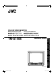
COLOUR VIDEO MONITOR : FARB-VIDEO-MONITOR : MONITEUR VIDÉO COULEUR : MONITOR VIDEO A COLORI : MONITOR DE VIDEO A COLOR INSTRUCTIONS – + B ESPAÑOL ITALIANO FRANÇAIS DEUTSCH TM-A140E ENGLISH BEDIENUNGSANLEITUNG MANUEL D’INSTRUCTIONS ISTRUZIONI MANUAL DE INSTRUCCIONES A ON OFF PHASE TM-A140E CHROMA BRIGHT CONTRAST MENU VOLUME/SELECT INPUT SELECT POWER LCT2142-001A-H cover1_TM-A140E_f.indd 1 06.6.
Thank you for purchasing this JVC colour video monitor. Before using it, read and follow all instructions carefully to take full advantage of the monitor’s capabilities. SAFETY PRECAUTIONS In order to prevent any fatal accidents caused by misoperation or mishandling the monitor, be fully aware of all the following precautions. WARNINGS To prevent fire or shock hazard, do not expose this monitor to rain or moisture. Dangerous high voltages are present inside the unit.
POWER CONNECTION WARNING The wire which is coloured green-and-yellow must be connected to the terminal which is marked with the letter E or the safety earth symbol or coloured green or green-and-yellow. The wire which is coloured blue must be connected to the terminal which is marked with the letter N or coloured black. If nonetheless the mains plug is cut off, remove the fuse and dispose of the plug immediately, to avoid a possible shock hazard by inadvertent connection to the main supply.
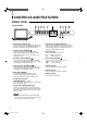
CONTROLS AND FEATURES FRONT VIEW – + B A ON OFF PHASE CHROMA BRIGHT CONTRAST MENU VOLUME/SELECT INPUT SELECT TM-A140E – + B POWER A ON OFF PHASE CHROMA BRIGHT TM-A140E CONTRAST MENU VOLUME/SELECT INPUT SELECT POWER 1 Phase button [PHASE 8 Input A button [INPUT SELECT A] ] Press this button to set the picture hue adjustment mode. Adjust the value with the VOLUME/SELECT buttons. Also used as a control button in the menu function mode.
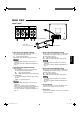
REAR VIEW VIDEO A IN OUT AUDIO B IN OUT A Y/C IN B IN OUT VIDEO A IN OUT AUDIO B IN OUT A Y/C IN B IN OUT For United Kingdom To AC outlet (230 V AC, 50 Hz/60 Hz) Video signal input (IN) and output (OUT) terminals. The output terminal is bridge-connected. IN : Video signal input terminal OUT : Bridge-connected video signal output terminal Notes: * For corresponding audio signals, use the AUDIO A terminals y. * Also refer to the BASIC CONNECTION EXAMPLE on page 11.
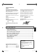
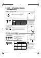
HOW TO HANDLE BASIC OPERATIONS BASIC OPERATION Colour system indication (PAL or NTSC) 1. Press the POWER switch to turn on the power. ON OFF _ON : Power turns ON. (Power indicator: lit) —OFF : Power turns OFF. (Power indicator: unlit) PAL POWER 2. Press the INPUT SELECT button to choose input. B Selects video/audio signals input to terminals on the rear panel.
HOW TO USE THE MENU FUNCTIONS DISPLAY AND SELECTION IN THE
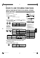
HOW TO USE THE MENU FUNCTIONS (cont’d) DISPLAY AND SELECTIONS IN THE MODE (SETTING) screen You can set the following set-up menu items. ● H. POSITION ● WHITE BALANCE ● CONTROL LOCK Note: ● Parameters for H. POSITION can be set separately depending on the video input (Input A or Input B) selected by the input select buttons on the front panel. Select the required video input with the input select buttons on the front panel in advance. 1 ‰ H.
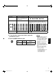
H. POSITION WHITE BALANCE DRIVE CUT OFF Purpose Settings Adjusts the horizontal position of the screen (+ : Horizontal position shifts to the right/–: Horizontal position shifts to the left). –05 –04 •• –01 00 +01 •• +04 +05 Adjusts the white balance. Selects DRIVE (DRV) or CUT OFF (CUTO) adjustment. Screen setting is changed to the selected setting mode. Select R/G/B buttons corresponding to the function display to adjust. R.DRIVE Adjusts red level.
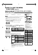
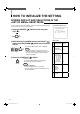
HOW TO INITIALIZE THE SETTING SCREEN DISPLAY AND SELECTIONS IN THE RESET MODE You can set
BASIC CONNECTION EXAMPLE Notes: ● Before connecting your system, make sure that all units are turned off. ● The illustration below shows some examples of different connections. Terminal connections may differ depending on the component connected. Be sure to refer to the instructions provided with the unit(s) you are connecting. ● Each pair of input (IN) and output (OUT) terminals are bridge-connected. However, the Y/C input terminal (Y/C IN) has no output terminal (OUT) corresponding to it.
TROUBLESHOOTING Solutions to common problems related to your monitor are described here. If none of the solutions presented here solves the problem, unplug the monitor and consult a JVC-authorized dealer or service center for assistance. Problems Points to be checked Measures (Remedy) No power supply. Is the power plug loosened or disconnected? Firmly insert the power plug. No picture with the power on. Is the video signal output from the connected component? Set the connected component correctly.
SPECIFICATIONS MODEL TM-A140E Type Colour video monitor Colour system PAL, NTSC (3.58) Picture tube 36 cm measured diagonally, 90° deflection, in-line gun, vertical line trio type (phosphor stripe pitch 0.64 mm) Effective screen size Width Height Diagonal 280.8 mm 210.6 mm 335.4 mm Scanning frequency H : 15.734 kHz (NTSC), 15.625 kHz (PAL) V : 59.
7 Dimensions Unit : mm < Side View > < Front View > 368.5 346 217 * 363.5 1.5 + B A ON OFF PHASE CHROMA BRIGHT CONTRAST MENU VOLUME/SELECT TM-A140E INPUT SELECT 5 – 3.5 310 287 * POWER 284 63.7 273 * Asterisks (∗) are used to indicate front panel dimensions. 7 Y/C (Mini DIN 4 pin) terminal specification Y/C IN 4 3 2 1 Pin No. Signal 1 GND (Y) 2 GND (C) 3 Y 4 C 14 02-15EN_TM-A140E_f.indd 14 06.6.
ENGLISH 15 02-15EN_TM-A140E_f.indd 15 06.6.
TM-A140E © 2006 Victor Company of Japan, Limited cover4_TM-A140E_f.indd 72 0606STH-MW-MT 06.6.