EN CAUTION RISK OF ELECTRICAL SHOCK DO NOT OPEN CAUTION: To reduce the risk of electric shock. Do not remove cover (or back). No user serviceable parts inside. Refer servicing to qualified service personnel. The lightning flash with arrowhead symbol, within an equilateral triangle is intended to alert the user to the presence of uninsulated “dangerous voltage” within the product’s enclosure that may be of sufficient magnitude to constitute a risk of electric shock to persons.
Table of Contents Safety Precautions 3 IMPORTANT SAFEGUARDS ............................................................................... 3 Caution for use of the product for many hours...................................................... 5 Caution for use of the product in the high temperature ........................................ 5 Maintenance ......................................................................................................... 5 Installation 6 Connections 8 Rear panel ..
Safety Precautions WARNING: TO REDUCE RISK OF FIRE OR ELECTRIC SHOCK, DO NOT EXPOSE THIS APPARATUS TO RAIN OR MOISTURE. NO OBJECTS FILLED WITH LIQUIDS, SUCH AS VASES, SHALL BE PLACED ON THE APPARATUS. IMPORTANT SAFEGUARDS Electrical energy can perform many useful functions. This unit has been engineered and manufactured to assure your personal safety. But IMPROPER USE CAN RESULT IN POTENTIAL ELECTRIC SHOCK OR FIRE.
Safety Precautions (cont.) • Slots and openings in the cabinet are provided for ventilation. These ensure reliable operation of the product and protect it from overheating. These openings must not be blocked or covered. • Never push objects of any kind into this product through openings as they may touch dangerous voltage points or short-circuit the parts, which could result in a fire or electric shock. • Never spill liquid of any kind on the product. • Never place anything on the product.
European Union only EN Dear Customer, EMC Supplement This apparatus is in conformance with the valid European directives and standards regarding electromagnetic compatibility and electrical safety. European representative of Victor Company of Japan, Limited is: JVC Technical Services Europe GmbH Postfach 10 05 04 61145 Friedberg Germany This equipment is in conformity with the provisions and protection requirements of the corresponding European Directives.
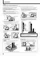
Installation CAUTION • Do not rest your arm on the monitor or lean against the monitor. • Do not touch the LCD panel when installing the monitor. • Be sure to install the monitor securely to prevent the monitor from falling over, which may cause damage to the monitor or injury. To install the monitor on a shelf or any other suitable surface using screws You can install the monitor without protruding the stand bottom plate by moving the stand bottom plate to the rear position.
To install the monitor on a wall You can install the monitor on a wall by changing how the stand bottom plate is attached. 1 Lay the monitor on a cloth with the LCD panel facing down to prevent the LCD panel from being damaged. Loosen the stand screws on the stand support and remove the bottom plate. Installation Only for Authorized Service Personnel Consult authorized service personnel for the installation of this unit. Installation instructions must be followed precisely in order to prevent accidents.
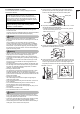
Connections Rear panel DT-R24L4D DT-R17L4D The illustration of the monitor is of DT-R24L4D. DT-R24L4D DT-R17L4D Security slot Attach a security wire to this slot. 1 POWER switch Turns AC power on or off. • You need to press button (☞ t on page 10) to use the monitor after turning on the POWER switch. 2 AC IN terminal AC power input connector. Connect the provided AC power cord to an AC outlet.
6 For DT-R24L4D: AUDIO ASSIGN (MONITOR OUT) terminals (pin jack) / For DT-R17L4D: AUDIO (MONITOR OUT) terminals (pin jack) Output terminals for the analog audio signal. • For DT-R24L4D: The terminals output the audio signal through AUDIO ASSIGN (IN 1 or IN 2) terminals when you select the video input you have selected for “AUDIO1 ASSIGN.” or “AUDIO2 ASSIGN.” in “AUDIO SETTING” (☞ page 14).
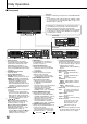
Daily Operations Front panel Tally lamp This lamp is controlled by the tally function of the MAKE/TRIGGER terminal. • You can select the color of the tally lamp from “GREEN” or “RED.” (☞ “TALLY SELECT” in “FUNCTION SETTING” on page 15 and “External Control” on page 18) The illustration of the monitor is of DT-R24L4D. • “NO EFFECT” is displayed when you press a button which is not available for the current input or signal format (the lamp lights even when the function does not actually work).
Audio Channel Selection Select audio channels emitted from the speakers (L/R) and the AUDIO ASSIGN (DT-R24L4D) / AUDIO (DT-R17L4D) (MONITOR OUT) (OUT1(L)/OUT2(R)) terminals, when EMBEDDED AUDIO signals come in to the E. AUDIO HD/SD SDI terminal (IN1 or IN2) and SDI input (1 or 2) is selected. • You have to choose a group of selectable audio channels before the channel selection. (☞ “E.AUDIO GROUP” in “AUDIO SETTING” on page 14) • The setting is memorized for each input (SDI 1 and SDI 2).
Menu Configuration The operation procedure 1 Display the menu. To display the MAIN MENU ¨ Press MENU button. To display the SET-UP MENU button while holding ¨ Press 2 Press MAIN MENU button. Operation guide buttons to select an item, then press • For some items, adjustments will be made by pressing button. Ex.: When “MARKER” in the MAIN MENU is selected . 3 Press buttons to select an item, then press 4 Press MENU button to finish the menu operation. buttons to make adjustments.
MAIN MENU EN PICTURE FUNCTION Setting for the picture quality Item To do Setting value APERTURE*1 Activates/deactivates the function at the level set in “APERTURE LEVEL.” OFF, ON Compensate the frequency response of the luminance signal of the video signal. 01 – 10 APERTURE LEVEL*1 CTI Adjust the clearness of the outlines of the chrominance signal. OFF, NORMAL, HARD LTI Adjust the clearness of the outlines of the luminance signal.
Menu Configuration (cont.) MARKER*1*2 Settings for marker functions 2/2 Item To do Activate/deactivate the area marker and select the style of it.*4 R-AREA MARKER*3 R-MARKER ASPECT*3 Select the aspect ratio of the area marker. R-SAFETY MARKER Activate/deactivate the safety marker and select the style of it.*4 R-SAFETY AREA Adjust the area of the safety marker. Setting value OFF, LINE, HALF, HALF+L, BLK. , BLK.+L 4:3, 14:9, 13:9, 2.35:1, 1.85:1, 1.66:1 OFF, LINE, HALF, HALF+L, BLK. , BLK.
SYNC FUNCTION Settings for the synchronization with signals Item To do NO SYNC ACTION Select the screen status when no signal is coming in. P.SAVE: power save mode GRAY B.: gray screen DELAY TIME Select the period until the screen status changes as selected in “NO SYNC ACTION” after signals stop coming in. LOW LATENCY Activates/deactivates the function to shorten the time taken to display the picture (low latency function). • If the picture is not displayed steadily while “ON” is selected, select “OFF.
Menu Configuration (cont.) SIZE/POSI. ADJ. Adjusts the size and position of the picture. Item To do Setting value Adjust the horizontal picture size. Setting value varies depending on H SIZE*1 the signals. H POSITION*1 Adjust the horizontal picture position. *1 Adjust the vertical picture size. V SIZE V POSITION*1 Adjust the vertical picture position. sub menu Display the sub menu which enables you to adjust the items of “SIZE/POSI. ADJ.” while viewing the actual picture.
INFORMATION EN Settings for the information display of the monitor Item To do Setting value POSITION UPPER, LOWER Select the position to show the information display (☞ “On the Information Display” on page 11). SOURCE ID Select whether the name assigned in “CHARACTER SET.” is displayed on the OFF, ON, AUTO screen (☞ “On the Information Display” on page 11). • When “AUTO” is selected, the display color synchronizes with the color of the tally lamp while the tally lamp is lit. CHARACTER SET.
External Control About the external control Using the MAKE/TRIGGER system This monitor has three external control terminals. The MAKE/TRIGGER terminal is configured as follows. You can assign a function to each pin terminal in “REMOTE SETTING” (☞ “PIN1, PIN2, PIN3, PIN4, PIN5” in “PARALLEL TYPE” on page 16). • You cannot change the functions assigned to the pin terminals from 6th to 8th. • MAKE/TRIGGER terminal (RJ-45): The following external control systems are available.
Display Functions to be controlled TALLY SEL Selects the color of the tally lamp. SDI 1 Changes the input to “SDI 1.” SDI 2 Changes the input to “SDI 2.” DVI Changes the input to “DVI.” VIDEO 1 Changes the input to “VIDEO 1.” DT-R24L4D VIDEO 2 Changes the input to “VIDEO 2.” DT-R17L4D VIDEO Changes the input to “VIDEO.” A.MARKER The area marker indication S.MARKER The safety marker indication FRAME Indication of the area of the specified aspect ratio C.
External Control (cont.) Using the serial communication You can control the monitor from a personal computer etc. via the RS-485 or RS-232C terminal. • Consult your dealer for the details of the external control specification. Input terminal Cable RS-485 RS-232C A straight LAN cable A straight cable with a D-sub 9-pin connector (male for the monitor, female for the personal computer etc.
No.
Troubleshooting Solutions to common problems related to the monitor are described here. If none of the solutions presented here solve the problem, unplug the monitor and consult an authorized dealer or service center. Symptom No power supply No picture with the power on No sound “OTHERS” or “Out of range” appears. “NO SYNC” appears. Probable cause and corrective action • Press the button. • Firmly insert the AC power plug. • Turn on the POWER switch on the rear panel.
Self-check program This monitor has a self-check function, which allows it to detect malfunctions and alert you. This makes troubleshooting easier. Whenever a problem occurs, one or some of the INPUT SELECT lamps will flash. If this happens, follow the steps below and contact your dealer to resolve the problem. The illustration of the monitor is of DT-R24L4D.
Specifications General Model name Type Screen size Aspect ratio Horizontal/vertical frequency (computer signal) DT-R24L4D DT-R17L4D Multi format LCD monitor Type 24 wide format Type 17 wide format 16:10 16:9 H: 31.469 kHz – 75.000 kHz V: 48 Hz – 65 Hz * Some signals within this frequency range may not be displayed (“Out of range” is displayed). Compliant video signal format ☞ “Available signals” on page 26 HD SDI: BTA S-004C, SMPTE292M SD SDI: ITU-R BT.
Dimensions Unit: mm (inch) EN DT-R24L4D 99 (4) 51.9 (2 1/8) 1.5 (1/8) 117 100 (4 5/8) 413.1 (16 3/8) 408 (16 1/8) 564 (22 1/4) VESA mounting holes (Size: M4, depth: 10 mm) 100 21 (7/8) 300 (11 7/8) 181(7 1/4) To install the monitor on a wall 30.3 (1 1/4) -φ 10 270 (10 3/4) 210 (8 3/8) 160 (6 3/8) 14.3 (5/8) 179 (7 1/8) 23.5 (1) 111.3 (4 1/2) 36.
Specifications (cont.) Available signals The following signals are available for this monitor. Video signals No. 1 2 3 4 5 6 7 8 9 10 11 12 13 14 15 16 17 18 19 20 21 22 23 24 25 26 27 28 29 30 31 32 33 34 35 36 37 Signal name NTSC PAL B/W50 B/W60 480/60i 480/59.94i 576/50i 480/60p 480/59.94p 576/50p 640*480/60p 640*480/59.94p 720/60p 720/59.94p 720/50p 720/30p 720/29.97p 720/25p 720/24p 720/23.98p 1080/60i 1080/59.94i 1035/60i 1035/59.94i 1080/50i 1080/60p 1080/59.94p 1080/50p 1080/30p 1080/29.
Computer signals (preset) DVI-D (HDCP) terminals No. 1 2 3 4 5 6 7 8 9 10 11 12 13 14 *4 Signal name VGA60 WVGA60 SVGA60 XGA60 WXGA (1280) WXGA+60*4 SXGA60*4 WSXGA+60*4 UXGA60*4 WUXGA60*4 720/60p 1080/60p*4 720/50p 1080/50p*4 Resolution Horizontal 640 852 800 1024 1280 1440 1280 1680 1600 1920 1280 1920 1280 1920 Vertical 480 480 600 768 768 900 1024 1050 1200 1200 720 1080 720 1080 Frequency Horizontal (kHz) Vertical (Hz) 31.5 59.9 31.5 59.9 37.9 60.3 48.4 60.0 47.8 60.0 55.9 60.0 64.0 60.0 65.2 60.