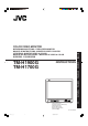
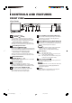
COLOR VIDEO MONITOR ESPAÑOL ITALIANO FRANÇAIS INSTRUCTIONS DEUTSCH TM-H1900G TM-H1700G ENGLISH BEDIENUNGSANLEITUNG : FARB-VIDEO-MONITOR MANUEL D’INSTRUCTIONS : MONITEUR VIDÉO COULEUR ISTRUZIONI : MONITOR VIDEO A COLORI MANUAL DE INSTRUCCIONES : MONITOR DE VIDEO A COLOR 使用說明書:彩色視頻監視器 PHASE VOLUME/SELECT MENU UNDER SCAN BRIGHT A B POWER INPUT SELECT 中文 CHROMA CONTRAST TM-H1900G (TM-H1900G shown) (Gezeigtes Modell ist TM-H1900G) (TM-H1900G montré) (Modello TM-H1900G) (Muestra de TM-H1900G)
TM-H1700G_CT 2 11/8/2007, 18:02
INSTRUCTIONS TM-H1900G TM-H1700G Thank you for purchasing this JVC color video monitor. Before using it, read and follow all instructions carefully to take full advantage of the monitor’s capabilities. LCT1092-003A-H[EN]3.p65 3 07.11.
SAFETY PRECAUTIONS In order to prevent any fatal accidents caused by misoperation or mishandling the monitor, be fully aware of all the following precautions. WARNINGS To prevent fire or shock hazard, do not expose this monitor to rain or moisture. Dangerous high voltages are present inside the unit. Do not remove the back cover of the cabinet. When servicing the monitor, consult qualified service personnel. Never try to service it yourself. WARNING : THIS APPARATUS MUST BE EARTHED.
POWER CONNECTION The power supply voltage rating of this product is AC 120 V (For U.S.A. and Canada only) and AC 230 V (For European countries or United Kingdom), the power cord attached conforms to the following power supply voltage and countries. Use only the power cord designated to ensure Safety and EMC regulations of each countries. Power cord Power supply voltage : AC 120 V Countries : U.S.A.
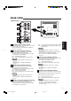
CONTROLS AND FEATURES FRONT VIEW 10 50C CHROMA CONTRAST TM-H1900G PHASE VOLUME/SELECT MENU UNDER SCAN BRIGHT A B CHROMA CONTRAST PHASE BRIGHT 1 2 POWER INPUT SELECT VOLUME/SELECT MENU UNDER SCAN A POWER B INPUT SELECT 3 4 6 5 7 8 9 (Front view of TM-H1900G shown) 1 Chroma/Phase button [ CHROMA/ PHASE] Press this button to activate the picture color density adjustment mode or picture hue adjustment mode.
REAR VIEW VIDEO A 12 IN OUT REMOTE 11 VIDEO B 13 IN OUT VIDEO A IN OUT VIDEO B IN IN IN 14 Y/C OUT Y/C OUT AUDIO A IN OUT AUDIO B IN OUT OUT AUDIO A 15 (Rear view of TM-H1900G shown) IN OUT AUDIO B IN OUT 11 REMOTE (external control) terminal Connect this terminal to an external control unit to enable remote operation of the monitor. Refer to the HOW TO USE EXTERNAL CONTROL on page 15 for more details.
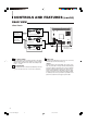
CONTROLS AND FEATURES (cont’d) REAR VIEW 19 To AC outlet (120 V AC, 50 Hz/60 Hz) REMOTE For U.S.A. and Canada VIDEO A To AC outlet (230 V AC, 50 Hz/60 Hz) IN OUT VIDEO B IN 19 IN OUT Y/C OUT AUDIO A IN For Europe OUT AUDIO B IN OUT 19 (Rear view of TM-H1900G shown) 18 For the United Kingdom 17 Main power switch Press the switch to turn the main power ON or OFF.
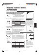
HOW TO HANDLE BASIC OPERATIONS BASIC OPERATION STATUS indication (PAL or NTSC) 1. Press the main power switch to turn on the power. 2. Press the POWER switch to turn on the power. PAL ON : Power turns ON. (Power indicator: lit) Green: The main power is ON, and the monitor’s power is ON (in the normal operation mode). OFF : Power turns OFF. (Power indicator: unlit) Orange : The main power is ON, but the monitor’s power is OFF (in the standby mode) Unlit : The main power is OFF. 3.
HOW TO HANDLE BASIC OPERATIONS (cont’d) VIDEO SIGNAL CONTROLS Use these buttons for video signal control. UNDER SCAN Press the UNDER SCAN button to reduce the size of display area so that the whole picture is displayed on screen. Use to check the picture frame. 8 LCT1092-003A-H[EN]3.p65 10 07.11.
HOW TO USE THE MENU FUNCTIONS DISPLAY AND SELECTION IN THE
HOW TO USE THE MENU FUNCTIONS (cont’d) DISPLAY AND SELECTIONS IN THE MODE (SETTING) You can set the following set-up menu items. • PICTURE SUB ADJ. • H. POSITION • V. POSITION screen • WHITE BALANCE • CONTROL LOCK • STATUS DISPLAY 1 • REMOTE SYSTEM • INPUT REMOTE 4 PICTURE SUB ADJ. H. POSITION V. POSITION WHITE BALANCE CONTROL LOCK STATUS DISPLAY REMOTE SYSTEM INPUT REMOTE Notes: ● Parameters for PICTURE SUB ADJ., H. POSITION and V.
Purpose PICTURE SUB ADJ. CONTRAST Selects CONTRAST/BRIGHT/CHROMA/PHASE. The selected setting screen is shown. Select the function display for adjustment. Adjusts contrast.
HOW TO INITIALIZE THE SETTING SCREEN DISPLAY AND SELECTIONS IN THE RESET MODE You can set
BASIC CONNECTION EXAMPLE Notes: • Before connecting your system, make sure that all units are turned off. • The illustration below shows some examples of different connections. Terminal connections may differ depending on the component connected. Be sure to refer to the instructions provided with the unit(s) you are connecting. • Each pair of input (IN) and output (OUT) terminals are bridge-connected.
BASIC CONNECTION EXAMPLE (cont’d) VIDEO B (Y/C) Connection Example (Select Input B (Y/C)) VIDEO A IN OUT VIDEO B Video Camera IN OUT Y/C (S-video) (Y/C (S-video) signal cable) VCR IN Y/C Video Monitor Y/C (S-video) (Y/C (S-video) signal cable) OUT AUDIO A IN VCR Audio (Audio signal cable) OUT AUDIO B IN Video Monitor Audio OUT (Audio signal cable) : Signal Flow 14 LCT1092-003A-H[EN]3.p65 16 07.11.
HOW TO USE EXTERNAL CONTROL ABOUT EXTERNAL CONTROL This monitor is provided with an external control terminal. MAKE (make contact) or TRIG. (trigger) system can be selected by the setting of REMOTE SYSTEM in the . MAKE (make contact system) : The function is controlled by short-circuiting or disconnecting each control terminal with pin 15 (GND). TRG. (trigger system) : The function is controlled by short-circuiting with pulses (for about 1 second) (short-circuit/open with the 15th pin GND).
TROUBLESHOOTING Solutions to common problems related to your monitor are described here. If none of the solutions presented here solves the problem, unplug the monitor and consult a JVC-authorized dealer or service center for assistance. Problems No power supply. Points to be checked Measures (Remedy) Is the power plug loosened or disconnected? Firmly insert the power plug. Is the main power turned OFF? Turn the main power ON. (See page 6.
SPECIFICATIONS MODEL TM-H1900G TM-H1700G Type Color video monitor Color system PAL, NTSC (3.58) 49 cm (19") measured diagonally, 90° deflection, in-line gun, trio-dot type (phosphor dot-trio pitch 0.27 mm) Effective screen size 44 cm (17") measured diagonally, 90° deflection, in-line gun, trio-dot type (phosphor dot-trio pitch 0.27 mm) Width 365.8 mm (14-5/8") Height 274.3 mm (10-7/8") Diagonal 457.2 mm (18") Width Height Diagonal 327.5 mm (12-7/8") 246.2 mm (9-5/8") 407.
SPECIFICATIONS (cont’d) Dimensions [TM-H1900G] Unit : mm (inch) < Side View > < Front View > 496 (19-5/8") 485 (19-1/8") 440 (17-3/8") 1.5 (1/16") VOLUME/SELECT UNDER SCAN MENU A BRIGHT POWER B INPUT SELECT 380.4 (15") 95.7 (3-7/8") 336 (13-1/4") 5 (1/4") PHASE 5 (1/4") CHROMA CONTRAST TM-H1900G 195.5 (7-3/4") 284.3 (11-1/4")* 375 (14-7/8") 375 (14-7/8")* ø20 (7/8") * Asterisks (*) are used to indicate front panel dimensions.
Y/C (Mini DIN 4 pin) terminal specification 2 4 1 3 OUT 2 4 1 3 Pin No. IN 1 GND (Y) 2 GND (C) 3 Y 4 C ENGLISH Y/C Signal 19 LCT1092-003A-H[EN]3.p65 21 07.11.
TM-H1900G/TM-H1700G © 2007 Victor Company of Japan, Limited TM-H1700G_CT 22 1107STH-MW-MT 11/8/2007, 18:04