CS-DR621 MWL CS-DR620MBL MARINE SPEAKER INSTRUCTION MANUAL HAUT-PARLEUR MARINE MODE D'EMPLOI ALTAVOZ MARINO M ANUAL DE INSTRUCCIONES JVCKENWOOD Corporation © 2020 JVCKENWOOD Corporation BSA-3569-00/ 00 (K)
IMPORTANT SAFETY INSTRUCTIONS & Caution: Read this page carefully to ensure sa fe operation. A WARNING Before mounting or wiring etc., be sure to remove the wire from the battery ground terminal. (Not doing so can cause shorts or fires.) When extending the power supply wire (+ 12 V) or ground wire, make sure to use automotive-grade wires or other wires with the range of 0.5 mm 2 (AWG 20) to 2 mm 2 (AWG 18) to prevent wire deterioration and damage to the wire coating.
Parts I Pieces I Piezas No. No No Part Name Designation des pieces Nombre de pieza Outside Shape Forme exterieure Forma externa Quantity Quantite Cantidad Part Name No. No Designation des pieces No Nombre de pieza Speaker A (6.
Connections I Raccordements I Conexiones Lt. WARNING ILt. AVERTISSEMENT I Remove the ignition key and disconnect the negative 0 terminal of the battery to prevent short circuits. Lt. CAUTION Check that no unconnected wires or connectors are touching the metal parts or car body. ■ Wiring • In a computer-equipped boat/vehicle, when you remove the e terminal of the battery, the memory may disappear, or a defect may occur in the electrical system of the boat/vehicle. Consult your dealer for further details.
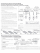
Connecting the power supply wires and link cable (RGB LED) Connexion des fils d'alimentation et du cable de liaison (DEL RGB) Conexion de los cables de la fuente de alimentacion y el cable de enlace (LED RGB) 1. Pass 2 heat shrink tubes® onto the link cable B ®· 2. Connect the link cable B ® to the left and right speakers. 3. Put the heat shrink tube ® over the connection area of the connector. Apply heat with a heat gun or similar to shrink the tube and protect the connector from moisture, etc.
■ When using multiple pairs of speakers Lors de !'utilisation de plusieurs paires de haut-parleurs Cuando se usan varios pares de altavoces A maximum of up to 6 pairs of speakers can be connected. Connect the link cables of the second and subsequent pairs of speakers as shown on the right. The figure shows an example of connecting 3 pairs of speakers. Connect the fourth and subsequent pairs speakers in the same way as the third pair.
Installation I Installation I lnstalaci6n ■ Speaker locations/ Emplacement des haut-parleurs / Ubicacion de los altavoces - - -, -_ ~ •u ~ ·:;) ·: .:\ . __ j · • ' • • ' ~ ■ Q ,;fjJjjj, - ~ I Fig. 7 Examples of speaker locations Fig. 7 Exemples d'emplacements de haut-parleur Figura 7 Ejemplos de ubicaciones de los altavoces How to use the template/ Utilisation du gabarit / Forma de utilizar la plantilla D Fig.
Controls I Contra/es I Contra/es ,1, CAUTION Do not leave or install the remote control in hot places such as on the dashboard. 6 ATTENTION Ne laissez pas ou n'installez pas la telecommande dans des endroits chauds comme sur le tableau de bord. I Lt PRECAUCION I No deje ni instale el mando a distancia en lugares calientes como el tablero de instrumentos. 0 C) (Turn on/Standby) 0 Press to switch the LED lights of t he speakers ON/OFF (standby mode).
■ How to replace the battery/ Comment remplacer la pile/ Como cambiar la bateria If the Remote Controller operates only over shorter distances or does not operate at all, it is possible that the battery is depleted. In such instances, replace the battery with new one. Si la telecommande fonctionne uniquement quand elle se trouve a de courtes distances, ou ne fonctionne pas du tout, ii est possible que la pile soit dechargee. Si tel est le cas, remplacez la pile par une neuve.
Troubleshooting Often, what appears to be a malfunction is due to user error. Before calling for service, please consult the following table. Problem RGB LED does not light. Remote control operation is not possible. Remedy Cause • The power supply of the+ 12 V wire is not connected. • Connect the wire correctly. • The link cable is connected improperly. • Insert the connector all the way in. • The remote control battery is exhausted. • Replace with new battery.
Specifications Specifications Design and specifications are subject to change without notice. La conception et /es specifications sont sujettes notification. Speakers Woofer ......................................................... 16 cm (6-1/2 in.) PP Mica cone Tweeter ............................................. 1.3 cm (1 /2 in.) PEI Balanced dome Peak power ..........................................................................................................260 W 75 Watts RMS Impedance .........
FCC CAUTION Changes or modifications not expressly approved by the party responsible for compliance could void the user's authority to operate the equipment. NOTE: This equipment has been tested and found to comply with the limits for a Class B digital device, pursuant to part 15 of the FCC Rules. These_ l1m1ts are designed to provide reasonable protection against harmful interference in a res1dent1al 1nstallat1on.
TEMPLATE JVCKENWOOD Corporation GABARIT PLANTILLA 4-04.
****************************************************************************** * i! JVC LIMITED WARRANTY I ONLy FOR PRODUCT PURCHASED IN U.S.A. I 1-1 I USA ONLY * JVCKENWOOD USA Corporation (JVC) warrants this product and all parts there of, except as set forth below ONLY TO THE * Ii! * ! ORIGINAL RETAIL PURCHASER to be FREE FROM DEFECTIVE MATERIALS AND WORKMANSHIP from the date of ! * original purchase for the period shown below.
TO OUR VALUED CUSTOMER - THANK YOU FOR PURCHASING THIS JVC PRODUCT. WE WANT TO HELP YOU ACHIEVE A PERFECT EXPERIENCE. NEED HELP ON HOWTO HOOK UP? NEED ASSISTANCE ON HOW TO OPERATE? NEED TO LOCATE A JVC SERVICE CENTER? LIKE TO PURCHASE ACCESSORIES? JVC IS HERE TO HELP! TOLL FREE: 1(800)252-5722 http://www. us.jvckenwood .com Remember to retain your Bill of Sale for Warranty Service. Do not attempt to service the product yourself Caution To prevent electrical shock, do not open the cabinet.