INSTRUCTIONS MANUEL D’INSTRUCTIONS MANUAL DE INSTRUCCIONES Preparation D-ILA PROJECTOR PROJECTEUR D-ILA PROYECTOR D-ILA DLA-RS40 DLA-RS50 DLA-RS60 Operation ON STAND BY COMPONENT HDMI 1 HDMI 2 COMP. ASPECT ANAMO INFO. LENS CONTROL LENS AP. C.M.
1 Getting started Safety Precautions IMPORTANT INFORMATION This product has a High Intensity Discharge (HID) lamp that contains mercury. Disposal of these materials may be regulated in your community due to environmental considerations. For disposal or recycling information, please contact your local authorities or for USA, the Electronic Industries Alliance: http://www.eiae.org. WARNING: TO PREVENT FIRE OR SHOCK HAZARDS, DO NOT EXPOSE THIS APPLIANCE TO RAIN OR MOISTURE.
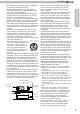
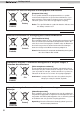
ENGLISH 150 mm and above 300 mm and above 150 mm and above 300 mm and above power source indicated on the label. If you are not sure of the type of power supply to your home, consult your product dealer or local power company. This product is equipped with a three-wire plug. This plug will fit only into a grounded power outlet. If you are unable to insert the plug into the outlet, contact your electrician to install the proper outlet. Do not defeat the safety purpose of the grounded plug.
1 Getting started - The product should be placed more than one foot away from heat sources such as radiators, heat registers, stoves, and other products (including amplifiers) that produce heat. - When connecting other products such as VCR’s, and DVD players, you should turn off the power of this product for protection against electric shock. - Do not place combustibles behind the cooling fan. For example, cloth, paper, matches, aerosol cans or gas lighters that present special hazards when over heated.
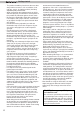
ENGLISH Safety Precautions (Continued) For USA and Canada only Use only the following power cord. Power cord The power supply voltage rating of this product is AC110V – AC240V. Use only the power cord designated by our dealer to ensure Safety and EMC. Ensure that the power cable used for the projector is the correct type for the AC outlet in your country. Consult your product dealer.
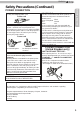
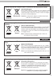
Getting started 1 ENGLISH Information for Users on Disposal of Old Equipment and Batteries [European Union only] These symbols indicate that equipment with these symbols should not be disposed of as general household waste. If you want to dispose of the product o r battery, please consider the collection systems or fa cilities for appr opriate recycling. Battery Products Notice: The sign Pb below the symbol for batteries indicates that this battery contains lead.
ENGLISH ESPAÑOL / CASTELLANO [Sólo Unión Europea] Estos símbolos indican que el equipo con estos símbolos no debe desecharse con la basura doméstica. Si desea desechar el pro ducto o batería/pila, acuda a los sistemas o centros de recogida para que los reciclen debidamente. Productos Baterías/pilas Atención: La indicación Pb debajo del símbolo de batería/pila indica que ésta contiene plomo.
Getting started 1 DANSK Brugerinformation om bortskaffelse af gammelt udstyr og batterier Batteri [Kun EU] Disse symboler angiver, at udstyr med disse symboler ikke må bortskaffes som almindeligt husholdningsaffald. Hvis du ønsker at smide dette produkt eller batteri ud, bedes du overveje at bruge indsamlingssystem et eller steder, hvor der kan ske korrekt gen brug. Bemærk: Tegnet Pb under symbolet for batterierne angiver, at dette batteri indeholder bly.
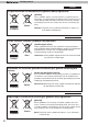
ENGLISH [только для Европейского союза] Данные символы указывают на то, что оборудование, на которое они нанесены, не должны утилизироваться, как обычные бытовые отходы. При необходимости утилизировать такое изделие или батарею обратитесь в специальный пункт сбора для их надлежащей переработки. Батарея Изделия Уведомление: Надпись Pb под символом батар ей указывает на то, что данная батарея содержит свинец.
1 Getting started THX Certification RS60 RS50 RS50 THX Certification Established by film producer George Lucas, THX aims to enhance the reproduction of audio sound and video images intended by filmmakers by setting quality standards for cinema viewing environments as well as home entertainment systems.
ENGLISH Getting Started For detail information about ISF, please refer web site http://www.imagingscience.
Getting started 1 Contents Getting started Safety Precautions ...........................2 RS60 ..................10 THX Certification RS50 RS50 Contents .........................................12 Accessories/Optional Accessories ....................................13 Check the Accessories .............................. 13 Optional Accessories ................................. 13 Controls and features ....................14 Main body - Front ......................................
ENGLISH Accessories/Optional Accessories Remote Control ..........................................................................1 piece AAA size Batteries (for operation confirm)..................................2 pieces Power Cord For the US market (2 m) .........................................1 piece Getting Started Check the Accessories Power Cord For the EU market (2 m) .........................................1 piece Power Cord For the UK market (2 m) .........................................
Getting started 1 Controls and features Main body - Front ③ Indicator STANDBY/ON LAMP WARNING ④ Exhaust Vent ① Lens ④ Exhaust Vent ② Remote receiver (front) ① Lens ③ Indicator ② Remote receiver (front) ④ Exhaust Vent This is a projection lens. Please do not look inside during projection. Please aim the remote control at this area when using it. * There is also a remote receiver at the rear. Please see “About the indicator display” for details.
ENGLISH Controls and features (continued) ⑤ Inlets ⑨ Lamp Cover ⑤ Inlets ⑧ Input terminal ⑫ Power input terminal Getting Started Main body - Rear ⑩ Operation panel ⑪ Light receiving section of the remote control (rear) ⑧ Input terminal ⑪ Light receiving section of the remote control (rear) There is also a terminal other than the input terminal for video images, such as those used for controlling or optional equipment. This RS60 .
Getting started 1 Controls and features (continued) Main body - About the indicator display Warnings and indications used during normal operation mode of this unit are displayed with the indicators for [STAND BY / ON], [LAMP], [WARNING] at the front of this unit. Meaning of the lighting figures: The display the indicator lights. They display flashing of the indicator. Operation mode display Displays the color and lighting/flashing of the [STAND BY / ON] indicator.
ENGLISH Controls and features (continued) Warning display You are informed of the contents of warning notices by the (repeated) displays of the [WARNING] and [LAMP] indicators. Moreover, the [STAND BY / ON] indicator, which shows the operating mode of the unit, is displayed simultaneously as described above. Upon activation of the warning mode, the projection is interrupted at the same time for about 60 seconds and the cooling fan is turned on.
Getting started 1 Controls and features (continued) Main body - Input terminal ① HDMI 1 ② HDMI 2 ③ LAN RS60 RS50 RS50 ⑤ COMPONENT ④ RS-232C ⑨ REMOTE ⑥ 3D SYNCHRO ⑦ PC ⑧ TRIGGER ① HDMI 1 Terminal ⑥ 3D SYNCHRO terminal ② HDMI 2 Terminal ⑦ PC terminal “D-Sub 15 pin” You can connect a device equipped with HDMI output, etc. It is fitted to the M3 lock hole. Screw hole depth 3mm. (Reference page: 26) You can connect a device equipped with HDMI output, etc. It is fitted to the M3 lock hole.
ENGLISH Controls and features (continued) Control To turn off the power RS60 RS50 RS50 ON STAND BY To turn on the power INPUT HDMI 2 COMP. To set the screen size (Reference page: 34) Anamorphic HDMI 1 ASPECT ANAMO PC To control lens (Reference page: 32) LENS. CONTROL To hide the image temporarily(Reference page: 36) To select input mode (Reference page: 32) RS40 INFO. Button: displays information RS50 Getting Started ■ Remote Lens Aperture LENS AP. HIDE C.M.
Preparation 2 About installation Important points concerning the installation Please read the following carefully before the installation of this unit. Please be careful when using Installation environment CAUTION CAUTION This unit is a precision device. Therefore, please refrain from installation or use in the following locations. Otherwise, it may cause fire or malfunction. • Dust, wet and humid locations. • Sooty or cigarette smoke filled locations.
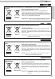
ENGLISH About installation (Continued) Installing the Projector and Screen While installing, please place this unit and the screen perpendicular to each other. Failing to do so may increase trapezoidal distortion. (Reference page: 36, 52) Set Angle Preparation ● 30° 30° 30° 30° The angle range which can be set for this unit is ±30°. Malfunctions may occur if the angle is not set within the above-mentioned range.
2 Preparation About installation (Continued) Fixation of the projector Measures to prevent the unit from toppling or dropping should be taken for safety reasons and accident prevention during emergencies including earthquakes. When mounting this unit on a pedestal or ceiling, remove the 4 feet on the bottom surface and use all the 4 screw holes (M5 screws) to mount.
ENGLISH About installation (Continued) Screen Size and Projection Distance Determine the distance from the lens to the screen to achieve your desired screen size. This unit uses a 2.0x power zoom lens for projection. ■ Relationship Between Projection Screen Size and Projection Distance Projection Screen Approximate Projection Size Distance (Height, Width) W(Wide) to T(Tele) Aspect Ratio 16:9 Approx.1.78m to Approx.3.66m 70" (Approx.0.9, 1.5m) Approx.2.09m to Approx.4.28m 80" (Approx.1.0, 1.8m) Approx.
Preparation 2 About the connection Types of possible input signals (PC compatible) ● No. of No. Total No. effective dot CLK Total of dots of lines [MHz] dots [dot] [line] [dot] No. of effective lines [line] No. Designation Resolution fh [kHz] fv [Hz] 1 VGA 60 640 X 480 31.500 60.000 25.200 800 525 640 480 2 VGA 59.94 640 X 480 31.469 59.940 25.175 800 525 640 480 3 SVGA 60 800 X 600 37.879 60.317 40.000 1,056 628 800 600 4 XGA 60 1024 X 768 48.363 60.004 65.
ENGLISH About the connection (Continued) Connection to the unit ● Do not turn on the power until connection is complete. ● The connection procedures differ according to the device used. For details, refer to the instruction manual of the device to be connected. ● This device is used for image projection. Connect to an audio output device such as amplifier and speaker for audio output from the connected device. ● The images may not be displayed depending on the devices and cables to be connected.
Preparation 2 About the connection (Continued) ■ Connecting via HDMI Cable This unit Notebook PC STANDBY/ON INPUT 1 HDMI 2 OK CR/PR CB/PB RS-232-C 3D SYNCHRO PC BD/DVD recorder Y REMOTE TRIGGER CONTROL MENU BACK HDMI 1 input terminal HDMI 2 input terminal HDMI cable (sold separately) ● If HDMI output terminal noise is produced, take PCs (Notebook PC) away from this unit. ● For a transmission bandwidth in compliance with the HDMI standard, a 340MHz cable is recommended.
ENGLISH About the connection (Continued) ■ Connecting via Component Video Cable This unit STANDBY/ON INPUT OK BD/DVD player MENU C 1 HDMI BACK 2 CR/PR CB/PB RS-232-C 3D SYNCHRO PC Y REMOTE TRIGGER CONTROL Component video output terminals CR/PR (red) CB/PB (blue) Component video cable (sold separately) ● Y (green) Preparation To component video input terminals Set “COMP.” in the setting menu to “Y Pb/Cb Pr/Cr”.
Preparation 2 About the connection (Continued) ■ Connecting via PC Cable RS60 RS50 RS50 This unit STANDBY/ON Notebook PC INPUT 1 HDMI 2 OK CR/PR CB/PB RS-232-C 3D SYNCHRO Y REMOTE TRIGGER CONTROL PC MENU BACK To PC input terminal PC cable(sold separately) ● VGA output terminal For information on supported input signals, please refer to “Specifications”.
ENGLISH About the connection (Continued) ■ Connecting via Trigger Cable This unit STANDBY/ON INPUT 1 HDMI Screen 2 OK RS-232-C 3D SYNCHRO CR/PR CB/PB Y TRIGGER PC To Trigger output terminal REMOTE CONTROL MENU BACK CAUTION ● ● ● ● ● Trigger input terminal ( Φ 3.5) Preparation Trigger cable (sold separately) Do not supply the power to the other devices. Do not connect audio terminals of the other devices such as headphones etc.
Preparation 2 About the connection (Continued) ■ Connected by LAN terminal RS60 RS50 RS50 This unit HUB connection cable (sold separately) STANDBY/ON INPUT 1 HDMI Network 2 OK CR/PR CB/PB RS-232-C 3D SYNCHRO PC Y Server REMOTE TRIGGER CONTROL MENU BACK ● The network is used to control the unit. It is not used for transmission of the video signal. ● Please contact your network administrator for questions concerning the network connection.
ENGLISH About the connection (Continued) Connection of the power cord (provided) Once you have connected the equipment, connect the projector power cord.
Operation 3 Basic Operation Basic operation procedures 6 1 STAND BY ON Once you have finished the basic setup, the unit can normally be used just with the following operations. 1 Turn on power source ON INPUT HDMI 1 HDMI 2 COMP. ASPECT ANAMO PC LENS AP. C.M.D LENS. CONTROL HIDE STANDBY/ON 2 ● ● 3 4 5 2 ANIME NATURAL STAGE 3D USER1 USER2 THX GAMMA COLOR TEMP COLOR P.FILE Choose the projected image ● PICTURE MODE CINEMA The lens cover will be opened.
ENGLISH 5 Adjust the shift (image position) Lens Control MEMO LENS Shift Adjust accordingly by pressing the up/down buttons After adjusting the image position, it may be necessary to select “Pixel Adjust” from the Settings menu “Installation”. Select Back BACK Operate ● About Cool Down mode The Cool Down mode is a function to cool down the lamp for approximately 60 seconds after projection is complete.
Operation 3 Basic Operation (continued) Frequently used useful functions ON STAND BY You can change the screen size of the projected image or hide the surrounding area of an image for which quality at the outer area has deteriorated. A B INPUT A HDMI 1 HDMI 2 COMP. ASPECT ANAMO PC LENS. CONTROL LENS AP. C.M.D HIDE C D A Setting the Screen Size The projected image can be set to a most appropriate screen size (aspect ratio).
ENGLISH B MEMO ● Masking is available only when high definition images are input. Masking the Surrounding Area of an Image Images for which quality at the outer area has deteriorated can be projected by masking (hiding) the surrounding area of the projected image. 1 Project the image Image for which quality at the outer area has deteriorated. ON STAND BY 2 INPUT HDMI 1 HDMI 2 COMP. ASPECT ANAMO PC LENS. CONTROL LENS AP. C.M.
Operation 3 Basic Operation (continued) C Temporary turning-off of the video You can hide the image temporarily. HIDE ON STAND BY Green light blinks when the image is hidden. INPUT C HDMI 1 HDMI 2 COMP. ● Press the ASPECT ANAMO PC ● The power cannot be turned off when the image is temporarily hidden. LENS. CONTROL LENS AP. C.M.D HIDE LIGHT D HIDE button again to display image.
ENGLISH Adjustments and settings in the menu Structure of the menu hierarchy (summary) The Menu of this unit is organized as follows. As this is only a brief guideline, items, which might not be displayed due to certain settings, are still displayed in the illustration. Moreover, in regard to COM , it shows countermeasures for all kinds of devices, but there the values for setting and adjustment might be different. See “Description of menu items” (Reference: Since 45 and following) for details.
3 Operation Adjustments and settings in the menu (continued) [3] Installation [4] Display Setup COM COM Installation Display Setup Lens Control Back Color Pixel Adjust Menu Position Installation Style Keystone Anamorphic Front Menu Display Line Display Off Source Display Screen Adjust Black Level Exit MENU Logo Back BACK Continued from the previous page To “[3] Layers and organization of the installation submenu” 38 Exit MENU On 5sec On On Language Operate Select Black English
ENGLISH Adjustments and settings in the menu (continued) [5] Function [6] Information RS60 RS50 RS50 COM Information Function Trigger Off Input : HDMI-2 Off Timer Off Source : 1080p60 High Altitude Mode Off Deep Color : 10bit Communication Terminal LAN Lamp Time : 160H Network Lamp Reset Exit MENU Operate BACK Select Exit MENU Operate BACK RS60 RS50 RS50 RS40 RS50 Information Function Trigger Off Off Timer Off High Altitude Mode Off Lamp Reset Input Resolution H
Operation 3 Adjustments and settings in the menu (continued) [1] Layers and organization of the picture adjust submenu [1] Picture Adjust [1-1] Color temp. RS60 RS50 RS50 RS60 RS50 RS50 Picture Adjust Picture Adjust [1-1] [1-2] Color Temp. > Picture Mode Film Preset Color Profile Color Temp.
ENGLISH Adjustments and settings in the menu (continued) [2] Layers and organization of the input signal submenu [2] Input Signal [2-1] HDMI COM RS60 RS50 RS50 Input Signal [2-1] [2-2] [2-3] HDMI HDMI Input COMP. Color Space Picture Position Aspect(Video) 16:9 Mask Off Progressive Auto Operate MENU Enhanced Level Check PC Exit Input Signal Select Auto Control with HDMI Off 3D Format Auto Back BACK Operate Exit MENU Back BACK Select [2-2] COMP.
Operation 3 Adjustments and settings in the menu (continued) Layers and organization of the submenus [3] installation and [5] function [3-1] Lens Control COM [3] Installation Installation COM Lens Control Focus Installation [3-1] [3-2] Zoom Lens Control Shift Pixel Adjust Installation Style Keystone Anamorphic Lens Cover Front Off Screen Adjust Black Level Operate Exit MENU Off MENU BACK Select On Lock Exit Back Auto Image Pattern Operate Back BACK Select [3-2] Pixel Adjust
ENGLISH Adjustments and settings in the menu (continued) Menu operation button Operate the menu by use of the buttons on the main body or the remote control. Button This unit Remote Control MENU MENU Function Menu is displayed. While the menu is displayed, the menu screen is turned off. STANDBY/ON OK OK BACK BACK While showing "Main menu" (Layer 1) selected items are confirmed, and "Submenu" (Layer 2) will be displayed.
Operation 3 Adjustments and settings in the menu (continued) Menu operation procedure 1 Press MENU. The main menu is displayed on the screen. The submenu items, which are currently Picture Adjust selected, are shown. Currently selected menu Picture Mode items are highlighted and the icon is colored Color Profile Color Temp. in orange. Gamma Film Tone The submenu items, which are currently Contrast selected, are displayed.
ENGLISH Adjustments and settings in the menu (continued) Menu item description All numbers for the items within [ ]are default settings. ● It is possible to operate all items displayed in the menu display by pressing OK/BACK or the cursor (up, down, left, right arrows). ● Displayed items vary depending on the selected item in the menu and type of input signal or absence of any signal.
Operation 3 Adjustments and settings in the menu (continued) [Table 1] The setting contents and default values RS60 RS50 RS50 of the color profiles for the picture mode Picture Mode Color Profile Film Cinema Anime Natural Film 1 Cinema 1 Anime 1 Video Film 2 Cinema 2 Anime 2 Vivid Standard Standard Stage 3D THX Stage 3D THX Standard Standard Adobe Standard Vivid User 1, 2 Everything is displayed except for Film 1 and Film2.
ENGLISH Adjustments and settings in the menu (continued) Contrast Brightness Color Tint Advanced Reset Adjusts the contrast of the video images. Settings: (blackish) -50 50 (whitish) You can adjust the brightness of the video image. Settings: (dark) -50 to 50 (bright) Adjust the color intensity of the video images. Settings: (dim), -50 to 50 (saturated) Adjusts the image tint of the video images.
3 Operation Adjustments and settings in the menu (continued) [1-2] Advanced Sharpness NR RNR MNR BNR RS40 Color Space RS50 Standard Wide 1 Wide 2 Custom Gamma Color Management RS60 RS50 RS50 Clear Motion Drive Off Mode 1 Mode 2 Mode 3 Mode 4 Inverse Telecine CMD Demo Left Right Top Bottom Off Lens Aperture 48 You can set the sharpness and detail enhance to "[1-2-1] Sharpness" of the submenu Reduces the noise of the video images. Please adjust to your preference.
ENGLISH Adjustments and settings in the menu (continued) Lamp Power Normal High [1-2-1] Sharpness Sharpness Detail Enhance It is possible to change the brightness of the lamp. (*) If continually used with "High", the lamp will become dark earlier. (*) The more one lets the interior temperature of the device rise due to generation of heat, the less the level of tolerance against high temperatures. (*) For about 60 seconds after the lamp is lit, the lamp cannot be switched off.
Operation 3 Adjustments and settings in the menu (continued) [1-2-3] Color Management Custom 1~3 Pause On Off Color Selection Axis Position Hue Saturation Brightness RS60 RS50 RS50 Set the 7 color axis (red / orange / yellow / green / cyan / blue / magenta) color as you like and save it then. For example you may want to change only the red color of roses. Please adjust to your preference. According to your adjustments, the input image in the background changes.
ENGLISH Adjustments and settings in the menu (continued) Mask It hides the upper, lower, left and right borders of the screen with a black mask. Can be individually adjusted vertically and horizontally. Please adjust to your preference. Setting: Off, 2.5%, 5%, Custom [Off] Not masked. Compared to the original video images, around 2.5% around the video images are masked. Compared to the original video images, around 5% around the video images are masked. Off 2.
Operation 3 Adjustments and settings in the menu (continued) 3D Format Auto Frame Packing Side by Side Top and Bottom 2D [2-2] COMP. RS60 RS50 RS50 Color Space Y Pb/Cb Pr/Cr RGB [2-3] PC Auto Alignment Tracking Phase Picture Position Horiz. Vert. [3] Installation Lens Control Pixel Adjust Installation Style Front Ceiling Mount (F) Rear Ceiling Mount (R) Keystone Horizontal Vertical 52 Sets the format of the 3D input signal.
ENGLISH Adjustments and settings in the menu (continued) Anamorphic A B Off Screen Adjust Black Level The video images are projected after being enlarged in the vertical direction of the panel resolution. This setting is used when one uses the anamorphic lens to enlarge them in the horizontal direction. (*) Anamorphic mode cannot be set when there is a 3D signal input. If a 3D signal is fed in when Anamorphic mode is set to A or B, Anamorphic mode is automatically turned Off.
3 Operation Adjustments and settings in the menu (continued) Horiz. Red Horiz. Green Horiz. Blue Vert. Red Vert. Green Vert.
ENGLISH Adjustments and settings in the menu (continued) Off 1 Hour 2 Hours 3 Hours 4 Hours High Altitude Mode On Off Communication RS60 Terminal RS50 RS50 RS-232C LAN RS60 Network RS50 RS50 Lamp Reset [5-1] Network Power is not turned off. Power is turned off automatically after 1 hour. Power is turned off automatically after 2 hours. Power is turned off automatically after 3 hours. Power is turned off automatically after 4 hours. Set to use at low pressure locations (900m above sea level).
Operation 3 Operation guide (glossary) Gamma Curve The light output The description of the gamma curve that assumes a gamma curve unit. Please read the relevant detailed description and professional books. The gamma curve of the projector to the input video signal determines for each color the relative value of its light output.
ENGLISH Description of the 3D method This is a description for the 3D-method using this unit, 3D-glasses (sold separately: PK-AG1-B) and an 3D synchro emitter (sold separately: PK-EM1). Set the 3D TV and 3D compatibility software to an appropriate viewing standard. For viewing, a separate unit compatible with 3D playback is needed. For detailed description of other 3D methods, please read specialized books on this topic. (For the sake of explanation, a simplified and exaggerated picture is used.
Operation 3 Separate images which can be seen by the right eye and left eye, respectively, are taken and produced separately. Therefore, the image for the left eye is only visible to the left eye, and the images for the right eye only or the right eye. The Human brain perceives stereoscopic images based on image information on both sides. Left-eye image Right-eye image CAUTION Stereoscopic video image In most cases, 3D images taken or produced are horizontally arranged respectively.
ENGLISH The frame sequential method is a way of displaying video images left and right sequentially. The projector projects the video images used for the left- and right eyes onto the screen. The video images for the left and right side are only visible with the respective eye, as the left and right side of the 3D glasses are opened and shut by a liquid crystal shutter. As a result, the left and right images are seen by the eye and show a 3D image.
4 Maintenance Replacing the Lamp The lamp is a consumable item. If the image is dark or the lamp is turned off, replace the lamp unit. ● When the lamp replacement time approaches, a message is displayed on the screen and the condition is indicated by the indicator. (Reference page: 16 to 17, 67) CAUTION ● ● ● ● Do not insert your hands into the opening of the lamp! This could cause obvious deterioration of the equipment’s function, wounds and electric shocks.
ENGLISH 5 CAUTION Install the new lamp unit ● ● Handle 6 Tighten the screws of the new lamp unit ● screwdriver. Attach the lamp cover ● ● Insert the top part (with 2 claws) of the lamp cover into the unit. Fasten the screws with a screwdriver. MEMO After Replacing the Lamp ● Do not place the removed lamp unit at locations that is reachable by children or near combustible items. ● Dispose used lamp units in the same way as fluorescent lamps. Follow your local community rules for disposal.
Maintenance 4 Replacing the Lamp (Continued) Resetting lamp Time ON STAND BY After replacing a new lamp unit, please reset the lamp time. Description of two methods. INPUT HDMI 1 HDMI 2 COMP. ASPECT ANAMO PC LENS. CONTROL LENS AP. C.M.D HIDE Reset the lamp time from the menu screen. 1 Display the setting menu Picture Adjust LIGHT Picture Mode Film Color Profile Color Temp.
ENGLISH Reset the lamp time by remote control. 1 ON STAND BY Insert the power plug to the power outlet INPUT HDMI 1 HDMI 2 COMP. ASPECT ANAMO PC LENS. CONTROL LENS AP. C.M.D Red Lights 2 Must operate with the remote control in the standby mode (the projector is powered, but is not turned on). ● Press in the order as shown. ● Press each button within 2-second intervals and press the last button for 2 seconds or more.
4 Maintenance Method for cleaning and replacing filters Clean the filter regularly or air intake efficiency may deteriorate and malfunction may occur. 1 Remove the inner filter. CAUTION ● ● Lift up while pushing the claw 2 Pull the power plug from the power outlet. Please turn this unit and if you put in on a bed or a table, first place something soft like a piece of cloth below. Then you can put it on top of it. Otherwise, it may cause scratches on this unit. Clean the filter.
ENGLISH Troubleshooting Before sending the unit to your authorized dealer for repair, please check the following points. The following situations are not malfunctions. ■ You do not need to worry about the following situations if there is no abnormality on the screen. ● ● ● ● Part of the top surface or front of the unit is hot. A creaking sound is heard from the unit. An operating sound is heard from the inside of the unit. Color smear occurs on some screens.
5 Others The picture cannot be projected Will the picture flicker and become invisible with HDMI input? Please use a short HDMI cable. Reference page: 26 The image cannot output by HDMI terminal Is the setup of “Control with HDMI” function “Off”? ● Set up the “Control with HDMI” function to “Off”. Reference page: 51 Even if the “Control with HDMI” function is “On”, there are still some devices cannot reveal image normally.
ENGLISH In case this message is displayed Message Cause (Details) No device is connected to the input terminal. The input terminal is connected but there is no signal. COMP㧚 䇭NO Input Input the video signals. A video signal that cannot be used in this unit has been input. COMP. Input video signals that can be used. *The names of input terminals such as COMP. will be displayed in yellow This message is displayed when the accumulated lamp time has exceeded 2900 hours.
5 Others RS-232C Interface It is possible to control this machine, if it is connected by an RS-232C cross cable (D-Sub9 pin) to a PC. Otherwise, this machine can be controlled via a computer network by connecting it with a LAN cable and sending of control commands. Please use it after you have understood this by reading professional books, or by discussing it with a system administrator. RS-232C Specifications This unit Pin No.
ENGLISH RS-232C Interface (Continued) Command Format The command between this unit and the computer consists of “Header”, “Unit ID”, “Command”, “Data” and “End”. ● Header (1 byte), Unit ID (2 bytes), Command (2 bytes), Data (n bytes), End (1 byte) ■ Header This binary code indicates the start of communication.
5 Others Reference command and data (Binary code) Command Type 5057 Power supply 4950 Input Data description During standby or power on 30: Standby mode 31: Power-on mode 32: During Cool Down mode 34: Warning mode During power on 32: COMP. RS60 32: PC RS50 RS50 36: HDMI 1 37: HDMI 2 ■ End This code indicates the end of communication. The binary code is fixed at “0A”. ■ Remote control code ● Binary code is sent during communication.
ENGLISH RS-232C Interface (Continued) RS-232C Communication Examples This section shows the communication examples of RS-232C. ■ Operating command Type Command Description Connection check PC→This unit: 21 89 01 00 00 0A This unit→PC: 06 89 01 00 00 0A Connection check. Power (On) PC→This unit: 21 89 01 50 57 31 0A This unit→PC: 06 89 01 50 57 0A When power is turned on from standby mode.
5 Others Copyright and Caution About Trademarks and Copyright ● HDMI, HDMI logo and high definition multimedia interface are trademarks or registered trademarks of HDMI Licensing LCC. Caution D-ILA Device Characteristics Maintenance Procedures Do not project still pictures or pictures that have still segments for a long period of time. The still parts of the picture may remain on the screen. Take special notice of images on the screens of video games and computer programs.
ENGLISH Specifications Product Name D-ILA Projector Model Name DLA-RS40-B, DLA-RS50-B, DLA-RS60-B *1 Display Panel/Size D-ILA device * 2 *3 0.7" (1920pixels x 1080pixels) x 3 (Total no. of pixels: Approx. 6.22million) Projection Lens 2.0 x power zoom lens (1.4:1 to 2.8:1) (Zoom/Focus: Power) Light-source Lamp 220 W Ultra-high pressure mercury lamp [Part No. :PK-L2210U] Average lifespan: 3000 hours (normal mode) Screen Size Approx. 60" to 200" (Aspect ratio: 16:9) Projection Distance Approx. 1.
5 Others * 1 Regarding -W the color of the main body is some kind of white color. Regarding –B, the color of the main body is some kind of black. * 2 D-ILA is the abbreviation for Direct drive Image Light Amplifier. * 3 D-ILA devices are manufactured using extremely high-precision technology. Pixel effectiveness is 99.99%. Only 0.01% or less of the pixels are either missing or would remain permanently lit up. * 4 HDCP is the abbreviation for High-bandwidth Digital Content Protection system.
ENGLISH Dimensions (Unit: mm) Top Surface Bottom Surface 290 ■ 91 472 ■ 5 Front ■ Back Surface 110 178.5 103.5 227.5 Lens center Φ60 32 24 ■ 337 59 455 Lamp cover 110 92 Connection terminal section of the RS60 .
5 Others Index [2] Input Signal ............................. Page 37, 41 3D Shorthand for "Three-dimensional" [3] Installation ............................... Page 38, 42 Operation Guide (Glossary) ............... Page 57 [4] Display Setup ............................... Page 38 Connection by 3D SYNCHRO terminal ............................................. Page 28 [5] Function ................................. Page 39, 42 3D format of [2-1] HDMI .....................
ENGLISH Index (continued) Message Meaning ............................................. Page 67 Lamp Replacement Lamp Number .............. Page 60 Recommended use time .................... Page 60 Lamp time of [6] Information .............. Page 55 Replacement ...................................... Page 60 Lamp power of [1-2] Advanced .......... Page 49 Lamp reset of [5] Function ................. Page 55 How to reset the lamp time .......... Page 62, 63 Notes of Caution ..................................
5 Others MEMO 78