PROJECTOR MANUEL D’INSTRUCTIONS : PROJECTEUR DLA-G15U FRANÇAIS ENGLISH INSTRUCTIONS For customer Use: Enter below the Serial No. which is located on the side panel of the cabinet. Retain this information for future reference. Pour l’utilisateur: Inscrivez ci-dessous le No de série situé sur le panneau latéral du coffret de l’appareil. Conservez cette information à titre d’information. OPERATE COMPUTER VIDEO T VOL. ZOOM FOCUS W PAGE BACK Model No.
INSTRUCTIONS PROJECTOR ENGLISH DLA-G15U 1
Thank you for purchasing this projector. Before using it, read and follow all instructions carefully to take full advantage of the projector's capabilities. SAFETY PRECAUTIONS IMPORTANT INFORMATION WARNING : TO PREVENT FIRE OR SHOCK HAZARDS, DO NOT EXPOSE THIS APPLIANCE TO RAIN OR MOISTURE. CAUTION : To reduce the risk of electric shock, do not remove cover. Refer servicing to qualified service personnel. This projector is equipped with a 3-blade grounding-type plug to satisfy FCC rule.
– This product should be operated only with the type of power source indicated on the label. If you are not sure of the type of power supply to your home, consult your product dealer or local power company. – The product should be placed more than one foot away from heat sources such as radiators, heat registers, stoves, and other products (including amplifiers) that produce heat. – This product is equipped with a three-wire plug. This plug will fit only into a grounded power outlet.
Contents SAFETY PRECAUTIONS ........................... 2 Operating the Setting Menu ................... 31 Accessories ............................................... 5 Making Basic Settings ......................................... 31 Controls and Features .............................. 6 Front Side / Top Surface / Right Side .................... 6 Left-hand side ....................................................... 7 Bottom Surface .....................................................
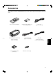
Accessories The following accessories are included with this projector. Check for them; if any item is missing, please contact your dealer. Personal computer connection cable [approx. 2 m (6.56 ft)] (D-sub, 3-row 15 pin) Conversion adapter for Mac (for Macintosh) AAA/R03-size dry cell battery (×2) (for checking operation) AV connection cable [approx. 1.5 m (4.92 ft)] Power code [approx. 2.5 m (8.2 ft)] Audio cable [approx. 3 m (9.84 ft)] (3.5 mm dia.
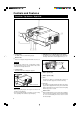
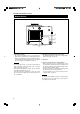
Controls and Features Front Side / Top Surface / Right Side G IN T R E T T E S U P M O C ID V O E C Y P N E G M E T R E M E P R E P T A D N A T S Y B O E L M A K IC N U IG QL A + 3 - 2 1 9 2 8 7 6 5 4 3 4 Adjustable foot (for adjusting upper/lower angles) 1 Control panel For details, refer to “Control Panel” (page 9). It is adjusted to be level when shipped from the factory. Turning to extend the foot allows adjustment up to + 7°.
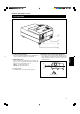
Controls and Features (cont.) Left-hand side p q w e This is the power input terminal where the supplied power cord is connected. For details, refer to page 24. q MAIN POWER switch This is the main power switch. When it is turned on, the projector goes into stand-by state, and the STAND BY indicator on the control panel comes on. ON [ ❙ ]: The main power turns on. ‡]: The main power turns off.
Controls and Features (cont.) Bottom Surface r t y u r Air intake area (filter) Air is taken in through this area to cool the light-source lamp. If this area is blocked or if something that obstructs taking in or exhausting air is placed around the projector, heat may build up inside and could cause a fire. For details, refer to “Precautions for Installation” on page 15. CAUTIONS • Be careful as paper, cloth or soft cushion could be drawn in if placed nearby.
Controls and Features (cont.) Control Panel STAND BY 1 4 Lamp indicator ON 2 OPERATE 3 LAMP 4 TEMP 5 EMERGENCY 6 VIDEO 7 COMPUTER 8 SETTING 9 : After the light-source lamp has been used for more than approx. 900 hours. Blinking : Replace the lamp. Refer to “Replacing the LightSource Lamp” on page 48. 5 TEMP indicator ON: The temperature inside the projector has abnormally risen.
Controls and Features (cont.) Control Panel (Cont.) 1 STAND BY 2 OPERATE 3 LAMP 4 TEMP 5 EMERGENCY 6 VIDEO 7 COMPUTER 8 SETTING 9 p QUICK ALIGN. button While a menu screen is shown, use this button to adjust the values for the item selected. When no menu is shown, the quick alignment function works. • When a menu is shown + 3 button: The value for the selected item increases. – 2 button: The value for the selected item decreases.
Controls and Features (cont.) Connector Panel w 1 2 Y/C VIDEO AUDIO q PC p AUDIO AUDIO R 9 G H/CS B V L Y R PB/B-Y 3 PR/R-Y 4 COMPUTER OUT REMOTE AUDIO OUT 6 5 RS-232C 7 1 Y/C (S video) input terminal (Mini DIN 4 pin) Connect this terminal to the S video output terminal of a video deck, etc. 2 VIDEO (composite video) input terminal (BNC) Connect this terminal to the composite video output terminal of a video deck, etc.
Controls and Features (cont.) Connector Panel (Cont.) w 1 2 Y/C VIDEO AUDIO q PC p AUDIO AUDIO R 9 G H/CS B V L Y R PB/B-Y 3 PR/R-Y 4 COMPUTER OUT REMOTE AUDIO OUT 6 5 RS-232C 8 7 9 COMPUTER IN (computer input) -2 terminal (BNC) These are input terminals for analog RGB signals, vertical sync (V) signals, and horizontal sync (H) signals / composite signals(Cs). Devices which have analog RGB signal output terminals can be connected.
Controls and Features (Cont.) Remote Control Unit 1 2 OPERATE e COMPUTER VIDEO T VOL. ZOOM FOCUS W PAGE BACK q MENU/ENTER 9 QUICK ALIGN. 1 Remote control’s signal transmitter 2 COMPUTER button Use this button to select the devices connected to the projector’s COMPUTER IN (computer input) -1 and -2 input terminals.
Controls and Features (cont.) Installing Batteries Install batteries in the remote control. If the remote control has started to work erratically, replace the batteries. 1 Open the back cover. While pushing on the back cover, slide it in the direction of the arrow. 2 Install the batteries. Place the two batteries (AAA/R03-size) supplied in the remote control as illustrated below. 3 Close the back cover. Slide the back cover in the direction of the arrow until a click is heard.
Installing the Projector Precautions for Installation CAUTION Do not install the projector in the following places : • There is much water, humidity or dust. • The projector may be subjected to oil smoke or cigarette smoke. • On a soft surface such as a carpet or cushion. • The projector may be subjected to direct sunlight. • Temperature is high or humidity is low.
Installing the Projector (Cont.) Projection Distance and Screen Size ■ The projector’s projection lens is a zoom lens of about 1.5 x. The screen size at the maximum enlargement is 1.5 times that of the minimum size. ■ The projection distance that can be focused is 2.5 to 20 m. Install the projector within this range.
Installing the Projector (Cont.) Relationship between Projection Distances and Projection Screen Sizes ■ For 4 : 3 aspect ratio screens Projection distance 8.2 ft (2.5 m) Projection screen size (diagonal length) Minimum projection screen size (Tele end) Maximum projection screen size (Wide end) 42” (approx. 107 cm) 63” (approx. 160 cm) 9.84 ft (3.0 m) 51” (approx. 130 cm) 76” (approx. 193 cm) 13.12 ft (4.0 m) 68” (approx. 173 cm) 102” (approx. 259 cm) 16.4 ft (5.0 m) 86” (approx.
Installing the Projector (Cont.) Effective Range and Distance of the Remote Control Unit The operable distance of the remote control unit is about 10 m (32.8 ft) for direct reception. The remote control can be used by having it reflected on the screen, etc. When you use the remote control by reflecting it at the screen, the total distance of A + B should be about 10 m (32.8 ft) or less. The operable angles of the remote control unit is 50° right to left, and 15° up and down.
Connecting to Various Devices * Before connection, be sure to turn off the projector and connected devices. * Read the manual which comes with each device thoroughly. Signals that Can Be Input to the Projector The following signals can be input to the projector: ■ Video signals (1) Response to color systems Color system Input terminal NTSC NTSC4.
Connecting to Various Devices (Cont.) Connecting to Video Devices Before connection, be sure to turn off both the projector and video device. • Read the manual which comes with each video device thoroughly. • Use the supplied AV connection cable. An AV connection cable with an S video terminal is not supplied.
Connecting to Various Devices (Cont.) Connecting to Other Devices Before connection, be sure to turn off both the projector and other devices to be connected. • Read the manual thoroughly which comes with the device to be connected. • Speakers with a built-in amplifier and game devices can be connected. Use the AV connection cable and audio cable supplied, or the cable supplied with a game device.
Connecting to Various Devices (Cont.) Connecting to Computer Devices Before connection, be sure to turn off both the projector and computer devices. • Read the manual which comes with each device thoroughly. ■ Connection to an IBM PC or IBM-compatible computer • Use the supplied computer connection cable. Also, prepare cables required for connecting the devices connected.
Connecting to Various Devices (Cont.) Connecting to Computer Devices (Cont.) Before connection, be sure to turn off both the projector and computer devices. • Read the manual which comes with each device thoroughly. ■ Connection to Macintosh • Use the supplied Personal computer connection cable and the supplied conversion adapter for Mac. • When connecting an audio output terminal such as a computer sound source to the projector, connect to the AUDIO terminal using the supplied audio cable.
Connecting to Various Devices (Cont.) Connecting the Power Cord (Supplied) After all devices have finished being connected, connect the projector’s power cord. At this time, do not turn on the MAIN POWER switch yet. 1 Insert the supplied power cord into the power input terminal (AC IN ~) of the projector. 1 AC IN ~ 2 Insert the plug of the supplied power cord into a wall outlet.
Connecting to Various Devices (Cont.) When Turning On the Devices Connected to the Projector Turn on the switches of the projector and the devices connected in the following order. Skip over unconnected devices if there is any. Power switch of the monitor of the computer which provides input to the projector ▼ Peripheral devices of the computer which provides input to the projector (Hard disk, magneto optical disk, scanner, etc.
Basic Operations ■ Projector’s buttons The following describes the basic procedure for normal use of the projector. 1. Turning on the Power STAND BY indicator STAND BY OPERATE indicator 1 Turn on the MAIN POWER switch. OPERATE button OPERATE 2, 1 LAMP TEMP ON [ ❙ ]:The main power turns on and the STAND BY indicator comes on. Projector’s indicator MAIN POWER switch EMERGENCY STAND BY 1, 2 VIDEO (ON) COMPUTER 2 Press the OPERATE button.
Basic Operations (Cont.) ■ Projector’s buttons 2. Select the video input to be projected STAND BY ■ Press the VIDEO button or the COMPUTER button to switch the input. • Each time you press either button, the selected input changes as follows. ■ When you press VIDEO: OPERATE LAMP Y/C Y,PB/B-Y,PR/R-Y VIDEO TEMP EMERGENCY ■ When you press COMPUTER: VIDEO button VIDEO COMPUTER 1 COMPUTER button COMPUTER Remote control unit SETTING +3 QUICK ALIGN.
Basic Operations (Cont.) ■ Remote control unit 4. Adjust focus ■ Adjust focus with the remote control’s FOCUS (+/–) buttons. OPERATE ■ To focus on farther points: Press the FOCUS (+) button. ■ To focus on nearer points: Press the FOCUS (–) button. COMPUTER VIDEO T VOL. ZOOM FOCUS W PAGE BACK MENU/ENTER FOCUS VOL. (+/–) buttons PRESET QUICK ALIGN. Remote control unit FOCUS (+/–) buttons AV MUTING Note • Focus adjustment can also be made on the setting menu.
Basic Operations (Cont.) ■ Remote control unit ¶ For Operating Other Functions ■ To turn off video image and audio sound temporarily OPERATE Press the AV MUTING button. ■ Press once: Video image and audio sound turn off (do not come out). ■ Press again: Video image and audio sound come out again. COMPUTER VIDEO T VOL. ZOOM Remote control unit FOCUS W MENU/ENTER PAGE BACK AV MUTING PRESET QUICK ALIGN. AV MUTING AV MUTING button QUICK ALIGN.
Basic Operations (Cont.) ■ Projector button ■ To display the SETTING menu The setting menu is used to make basic adjustments and settings (TRACKING, PHASE, H. POS., V. POS., FOCUS, ZOOM and AUDIO-VOL.) of the video picture being projected after installation (connection) or after inputs are switched. For operating the setting menu, refer to “Making Basic Settings” on page 31. STAND BY OPERATE • Press the projector’s SETTING button. The setting menu is displayed on the screen.
Operating the Setting Menu Making Basic Settings ■ Projector’s buttons Here, we make basic video adjustment and sound volume adjustment which are set up after installation (connection). EMERGENCY Notes VIDEO COMPUTER SETTING button SETTING +3 QUICK ALIGN. QUICK ALIGN. buttons -2 the SETTING button of the 1 Press projector. ■ Setting menu • The setting menu is displayed on the screen. SETTING TRACKING PHASE H.POS. V.POS. FOCUS ZOOM AUDIO -VOL.
Operating the Main Menu Configuration the Main Menu (AV Input) For computer inputs, see the following page. You can adjust video quality (PICTURE), audio quality (SOUND), etc. using the menus. The menus are configured as follows: Main menu (AV inputs : During AV IN input signal) PIXEL CLOCK TRACKING PHASE : Normally, no adjustment is required. The lateral size and display area of video image are adjusted. : Normally, no adjustment is required. Flickering or dim video image is adjusted. POSITION V. POS.
Operating the Main Menu (Cont.) Configuration of the Main Menu (Computer-related input) Main menu (Computer-related inputs : During COMPUTER IN-1 or -2 input signal) PIXEL CLOCK TRACKING PHASE : The lateral size and display area of video image are adjusted. : Flickering or dim video image is adjusted. POSITION V. POS. H. POS. : The vertical position of the video image being projected is adjusted. : The horizontal position of the video image being projected is adjusted.
Operating the Main Menu (Cont.) Operating the Main Menu (Basic Operation of the Main Menu) ■ Remote control unit OPERATE MENU/ENTER button COMPUTER VIDEO For projector’s menus, the setting menu and the main menu are available. Here, we explain about the operation of the main menu. (see pages 34 to 47) For the setting menu, refer to “Making Basic Settings” on page 31. 1 Press the MENU/ENTER button. • The main menu is displayed on the screen. T VOL.
Operating the Main Menu (Cont.) Changing the Color System ■ Remote control unit OPERATE COMPUTER VIDEO MENU/ENTER button AUTO is set for the color system when the projector is shipped from the factory. Normally, use it in AUTO. If operation in AUTO is unstable such as with color not being shown, set to a dedicated color system in accordance with the color system of the signal being input. 1 Press the MENU/ENTER button. • The main menu is shown on the screen.
Operating the Main Menu (Cont.) Changing the Language Display ■ Remote control unit OPERATE COMPUTER VIDEO MENU/ENTER button ZOOM FOCUS • The main menu is shown on the screen. • The selected item (displayed in text) is shown in magenta color on the screen. W MENU/ENTER PAGE BACK 1 Press the MENU/ENTER button. “LANGUAGE” with the cursor 2 Select button 5 or ∞ . T VOL. The language in the menu display is set to English when shipped from the factory.
Operating the Main Menu (Cont.) Adjusting the Pixel Clock ■ Remote control unit OPERATE COMPUTER VIDEO MENU/ENTER button The pixel clock should be adjusted mainly for computer-related inputs. (Normally, it does not need to be adjusted for video inputs.) If a wide stripe appears on the screen, adjust the lateral size of video image and the display area (tracking adjustment) so the stripe disappears.
Operating the Main Menu (Cont.) Adjusting the Screen Position ■ Remote control unit Adjust the position of the screen if it is displaced. 1 Press the MENU/ENTER button. • The main menu appears on the screen. OPERATE COMPUTER VIDEO MENU/ENTER button • The selected item (displayed in text) is shown in magenta color on the screen. T VOL. ZOOM “POSITION” with the cursor 2 Select button 5 or ∞ . FOCUS W 3 Press the MENU/ENTER button.
Operating the Main Menu (Cont.) Adjusting Picture Quality ■ Remote control unit OPERATE COMPUTER VIDEO MENU/ENTER button ZOOM FOCUS • The main menu appears on the screen. • The selected item (displayed in text) is shown in magenta color on the screen. W MENU/ENTER PAGE BACK 1 Press the MENU/ENTER button. “PICTURE” with the cursor 2 Select button 5 or ∞ . T VOL. Adjust brightness, contrast, etc. so you have the desired screen.
Operating the Main Menu (Cont.) Adjusting Picture Quality (Cont.) ■Remote control unit adjustment 5 Make button 2 or 3. with the cursor ■ For video system input OPERATE COMPUTER VIDEO MENU/ENTER button • To adjust multiple items, repeat steps 4 and 5. • To reset all items (to factory-set adjustment values “0”), select ALL RESET with the cursor buttons and press the MENU/ ENTER button.
Operating the Main Menu (Cont.) Adjusting Picture Quality (Cont.) Adjustment item Button 2 Gets darker. (–30 ← 0 ← +30) 3 Gets brighter. (–30 → 0 → +30) 2 Gets lower. (–30 ← 0 ← +30) 3 Gets higher. (–30 → 0 → +30) 2 Gets less reddish. (–30 ← 0 ← +30) 3 Gets more reddish. (–30 → 0 → +30) 2 Gets less greenish. (–30 ← 0 ← +30) 3 Gets more greenish. (–30 → 0 → +30) 2 Gets less bluish. (–30 ← 0 ← +30) 3 Gets more bluish.
Operating the Main Menu (Cont.) Adjusting Sound Quality ■ Remote control unit Adjust the quality (treble/bass) of sound. 1 Press the MENU/ENTER button. • The main menu appears on the screen. OPERATE COMPUTER VIDEO MENU/ENTER button • The selected item (displayed in text) is shown in magenta color on the screen. T VOL. ZOOM the “SOUND” with the cursor 2 Select button 5 or ∞ . FOCUS W 3 Press the MENU/ENTER button. MENU/ENTER PAGE BACK •The submenu items of the SOUND menu appear on the screen.
Operating the Main Menu (Cont.) Setting and Adjusting Other Functions (OPTIONS) ■ Remote control unit OPERATE COMPUTER VIDEO MENU/ENTER button The following optional functions can be set (adjusted). • MENU AUTO OFF • LINE DISPLAY • RIGHT LEFT REV. • TOP BOTTOM INV. • CLAMP • RESIZE • BACK COLOR • COLOR TEMPERATURE • ASPECT CHANGE • SLEEP TIME • LAMP TIME Memo About the lamp use time The lamp use time indicates the accumulated used hours of the light-source lamp and cannot be set or adjusted.
Operating the Main Menu (Cont.) Setting and Adjusting Other Functions (OPTIONS) (Cont.) ■Remote control unit (adjust) the desired item with the 5 Set cursor button 2 or 3. • To adjust multiple items, repeat steps 4 and 5. OPERATE COMPUTER VIDEO MENU/ENTER button Adjustment item Button MENU AUTO OFF 2/3 2/3 Sets whether to show the line display (Y/C, VIDEO, etc.) at the top of the projected screen or not. (Factory setting : ON) OFF: Does not show the line display. ON : Shows the line display.
Operating the Main Menu (Cont.) Setting and Adjusting Other Functions (OPTIONS) (Cont.) ■Remote control unit Adjustment item Button BACK COLOR OPERATE COMPUTER VIDEO 2/3 MENU/ENTER button ZOOM PAGE BACK COLOR TEMP. MENU/ENTER RED MAGENTA 2/3 Sets the color temperature of the video image being projected. Make adjustment when the image becomes reddish or bluish. (Factory setting : MIDDLE) LOW : Color temperature decreases (video image becoming reddish).
Operating the Main Menu (Cont.) Changing (Setting) the Source ■ Remote control unit OPERATE MENU/ENTER button COMPUTER VIDEO T VOL. ZOOM Normally, use the source setting in AUTO. If use in AUTO is unstable such as color not appearing, the screen being disturbed or the screen being intermitted, set to the dedicated source (forced mode) in accordance with the input signal.
Operating the Main Menu (Cont.) Changing (Setting) the Source (Cont.) ■ Remote control unit the MENU/ENTER button to set 5 Press (fix) it. ■ When AUTO is selected: OPERATE COMPUTER VIDEO MENU/ENTER button ZOOM setting procedure, and the source display inputted appears. • Both line display and source display appear on the screen and disappear in five seconds. However, they do not appear if the line display is set to OFF. T VOL.
Replacing the Light-Source Lamp The light-source lamp has its service life. It is approximately 1000 hours. When the light-source lamp approaches the end of its service life, its degradation progresses rapidly. When the lamp’s used hours exceed 900 hours, the projector’s LAMP indicator comes on. Also, at the start of projection (lamp energized), the message “REPL.-LAMP” appears on the projection screen for about two minutes. Then, replace with a new light-source lamp, or arrange for a replacement lamp.
Replacing the Light-Source Lamp (Cont.) the lamp-unit screws, raise 2 Loosen the handle, and pull out the lamp Screw unit. Loosen the two screws with a flat-end screwdriver. Note • The screws are fitted so that they do not come off the lampunit. Lamp unit 2 1 3 Handle Insert the new lamp unit fully inside and fasten the screws. Fasten the two screws with a flat-end screwdriver.
Replacing the Light-source Lamp (Cont.) Resetting the Lamp Use Time After replacing with a new light-source lamp, reset the counter inside the projector. This works to reset the life calculation of the light-source lamp, allowing the used time of the new light-source lamp to be accumulated. on the MAIN POWER switch 1 Turn to go into stand-by mode. ■Projector’s button • ON [ ❙ ]: The main power turns ON and the STAND BY [MAIN POWER switch] indicator lights.
Cleaning and Replacing the Filter Clean the filter periodically. If the filter is heavily stained and does not get clean, or if it is damaged, replace the filter with a new filter (part No.: LC30208). Otherwise, dirt may get inside and appear on the screen, possibly preventing you from enjoying the video image fully. If dirt gets inside or if you need information about the filter, consult a JVCauthorized dealer where you have purchased the projector or nearest JVC Service center.
Troubleshooting Solutions to common problems related to your projector are described here. If none of the solutions presented here solves the problem, unplug the projector and consult a JVC-authorized dealer or service center. Symptom Probable cause Power is not supplied. • Is the power cord disconnected? • Is the main power switch turned on? Corrective action • Insert the power cord (plug) firmly. Page 24 • Turn on the MAIN POWER switch.
Symptom The upper part of the video image bows or distorts. Probable cause • While computer system signal is input, isn’t a sync signal for composite sync (Cs) or G on sync being input? Corrective action • Input separate sync signals for vertical sync (V) and horizontal sync (H) signals. • Isn’t signal with much jitter or skew distortion being input to a video deck? • Input signals with little jitter or distortion. • Is the source setting correctly selected? • Set the source setting to AUTO.
Specifications Optical mechanism system • Projection method • D-ILA device • Projecting lens • Screen size • Light-source lamp 3D-ILA device, 1 lens, 3 primary color optical shutter method 0.9" measured diagonally (1365 ×1024 pixels) × 3 (Total number of pixels : 4,193,280) Electric-driven zoom of 1.5 × 42" to 300" [recommended] to 521" [maximum] measured diagonally (*with aspect ratio : 4 : 3) 420 W xenon lamp Electrical system • Color system • Resolution • Scanning frequency NTSC, NTSC4.
Specifications (Cont.) Horizontal sync/composite sync signal (H/Cs) H : 1 to 5Vp-p, high impedance (positive/negative polarity) Cs : 1 to 5Vp-p, high impedance (positive/negative polarity) Vertical sync signal (V) V : 1 to 5Vp-p, high impedance (positive/negative polarity) * Some connected devices may not correspond to composite sync (Cs) or G on sync signal. • AUDIO (For COMPUTER IN-2) 1-line, stereo mini-jack × 1 0.
Specifications (Cont.) Outside dimensions ■ Top 16-3/4 (425)*1 Unit: Inch (mm) 13-3/8 (339) 14-7/8 (375) *1: Protrusion excluded -2 QUICK ALIGN +3 SETTING COMPUTER VIDEO EMERGENCY TEMP LAMP STAND BY φ4-1/8 (φ104) 5-1/4 (133)*1 ■ Front ■ Side 6-5/8 (168) 14-1/4 (361) 1 9-1/8 (231) 1 8- /8 (205)* 2-1/4 (55.5) DTV-format signals * The following are DTV-format signals that can be input.
Specifications (Cont.) Pin assignment (Specifications for terminals) ■ Y/C terminal Pin number 4 2 3 1 Signal name 1 GND (Y) 2 GND (C) 3 Y 4 C Pin number Signal name Pin number Signal name 1 N/C 6 N/C 2 RD 7 N/C 3 TD 8 N/C 4 N/C 9 N/C 5 GND Signal name ■ RS-232C terminal 6 7 8 9 1 2 3 4 5 15 14 13 12 11 10 9 5 4 3 8 2 1 7 6 Pin number Signal name Pin number 1 Red 9 N/C 2 Green 10 GND (SYNC) 3 Blue 11 GND 4 N/C 12 N/C 5 N/C 13 H.
58
MANUEL D’INSTRUCTIONS PROJECTEUR FRANÇAIS DLA-G15U 1
Merci d’avoir acheté ce projecteur. Avant de l’utiliser, lisez et respectez attentivement toutes les instructions pour profiter au maximum des capacités du projecteur. PRÉCAUTIONS DE SÉCURITÉ INFORMATIONS IMPORTANTES AVERTISSEMENT: POUR ÉVITER TOUT RISQUE D’INCENDIE OU D’ÉLECTROCUTION, N’EXPOSEZ PAS CET APPAREIL À LA PLUIE OU À L’HUMIDITÉ. ATTENTION: Pour réduire les risques d’électrocution, ne retirez pas le couvercle. Référez-vous à un personnel qualifié pour toute réparation.
– Cet appareil doit être alimenté avec l’alimentation secteur indiquée sur l’étiquette. Si vous n’êtes pas sûr du type d’alimentation secteur de votre maison, consultez le revendeur de l’appareil ou votre compagnie d’électricité. – Après que cet appareil a subit une réparation ou un entretien, demandez au réparateur de réaliser les vérifications de sécurité pour déterminer si l’appareil est en état de fonctionnement correct. – Cet appareil est équipé d’une fiche à trois broches.
Table des matières PRÉCAUTIONS DE SÉCURITÉ ................. 2 Utilisation du menu de réglage .............. 31 Accessoires ............................................... 5 Réglages de base ............................................... 31 Commandes et fonctions ......................... 6 Face avant/ Surface supérieure/ Face droite ........ 6 Face gauche ......................................................... 7 Surface inférieure ..................................................
Accessoires Les accessoires suivants sont fournis avec ce projecteur. Vérifiez s’ils sont bien tous présents. Si l’un de ces accessoires manquait, veuillez contacter votre revendeur. Câble de connexion à l’ordinateur personnel [env. 2 m (6,56 pieds)] (D-sub, 15 broches sur 3 rangées) Adaptateur de conversion pour Mac (pour Macintosh) Piles sèches AAA/R03 (×2) (pour vérifier le fonctionnement) Câble de connexion audio/vidéo [env. 1,5 m (4,92 pieds)] Cordon d’alimentation [env.
Commandes et fonctions Face avant / Surface supérieure/ Face droite ID V M E T E S A T N D B Y O P E R T A E L A M M E P R G P E N C Y C O E M O P S U T E T E T R IN G K IC N U IG QL A + 3 - 2 1 9 2 8 7 6 5 4 3 4 Pied ajustable (pour l’ajustement de l’angle supérieur/ 1 Panneau de commande Pour plus de détails, référez-vous à “Panneau de commande” (page 9). 2 Évents de sortie d’air inférieur) A l’expédition de l’usine, il est ajusté pour être plat.
Commandes et fonctions (suite) Face gauche p q w e p Prise AC IN (entrée d’alimentation) C’est la prise d’entrée d’alimentation où le cordon d’alimentation est connecté. Pour les détails, référez-vous à la page 24. e Pied ajustable (pour l’ajustement de l’angle horizontal) Il est réglé sur la position la plus courte lors de l’expédition de l’usine. Tournez le pied pour mettre droit le projecteur. L’ajustement peut être fait dans une plage de + 1,5° et – 1,5° à partir de la position horizontale.
Commandes et fonctions (suite) Surface inférieure r t y ATTENTION u r Zone d’entrée d’air (filtre) L’air entre par cette zone pour refroidir la lampe source de lumière. Si cette zone est bloquée ou s’il y a quelque chose qui empêche l’entrée d’air placé autour du projecteur, la chaleur risque de s’accumuler à l’intérieur de l’appareil pouvant causer un incendie. Pour les détails, référez-vous à “Précautions pour l’installation” à la page 15.
Commandes et fonctions (suite) Panneau de commande 4 Indicateur LAMP 1 2 OPERATE 3 LAMP 4 TEMP 5 EMERGENCY 6 VIDEO 7 COMPUTER 8 SETTING 9 +3 QUICK ALIGN. p -2 1 Indicateur STAND BY Allumé : Quand l’appareil est en mode d’attente. Clignote: Quand l’appareil est en mode de refroidissement. Mémo À propos du mode de refroidissement: Ce projecteur a une fonction pour refroidir la lampe qui a chauffé pendant une période fixe de temps après que la projection est finie.
Commandes et fonctions (suite) Panneau de commande (suite) 1 STAND BY 2 OPERATE 3 LAMP 4 TEMP 5 EMERGENCY 6 VIDEO 7 COMPUTER 8 p Touches QUICK ALIGN. Quand un écran de menu apparaît, utilisez ces touches pour ajuster la valeur de l’élément choisi. Quand aucun menu n’apparaît, ces touches peuvent être utilisées pour la fonction d’alignement rapide. • Quand un menu apparaît Touche + 3: La valeur pour l’élément choisi augmente. Touche – 2: La valeur pour l’élément choisi diminue.
Commandes et fonctions (suite) Panneau de connexion w 1 2 Y/C VIDEO AUDIO q PC p AUDIO AUDIO R 9 G H/CS B V L Y R PB/B-Y 3 PR/R-Y 4 COMPUTER OUT REMOTE AUDIO OUT 6 5 RS-232C 7 1 Prise d’entrée Y/C (S vidéo) (Mini DIN 4 broches) Connectez cette prise à la prise de sortie S vidéo d’un magnétoscope, etc. 2 Prise d’entrée VIDEO (vidéo composite) (BNC) Connectez cette prise à la prise de sortie vidéo composite d’un magnétoscope, etc.
Commandes et fonctions (suite) Panneau de connexion (suite) w 1 2 Y/C VIDEO AUDIO q PC p AUDIO AUDIO R 9 G H/CS B V L Y R PB/B-Y 3 PR/R-Y 4 COMPUTER OUT REMOTE AUDIO OUT 6 5 RS-232C 8 7 9 Prises COMPUTER IN (entrée de l’ordinateur) -2 (BNC) Ce sont des prises pour les signaux RVB analogiques, les signaux de synchronisation verticale (V) et les signaux de synchronisation horizontale (H)/ signaux composites (Cs).
Commandes et fonctions (suite) Télécommande 1 2 OPERATE e COMPUTER VIDEO T w VOL. ZOOM FOCUS W PAGE BACK q MENU/ENTER 9 QUICK ALIGN. 1 Emetteur de signaux de télécommande 2 Touche COMPUTER AV MUTING 8 3 Touche VIDEO Utilisez cette touche pour choisir l’appareil vidéo connecté aux prise AV IN (entrée audio/vidéo) du projecteur.
Commandes et fonctions (suite) Mise en place des piles Installez les piles dans la télécommande. Si la télécommande a commencé à fonctionner irrégulièrement, remplacez les piles. 1 Ouvrez le couvercle arrière. Tout en appuyant sur le couvercle arrière, faites-le glisser dans la direction de la flèche. 2 Installez les piles. Placez les deux piles (AAA/R03) fournies dans la télécommande de la façon montrée ci-dessous. 3 Refermez le couvercle arrière.
Installation du projecteur Précautions pour l’installation ATTENTION N’installez pas le projecteur dans les endroits suivants: • Où il y a beaucoup d’eau, d’humidité ou de poussière. • Où le projecteur peut être sujet à de la fumée grasse ou à de la fumée de cigarette. • Sur une surface molle telle qu’un tapis ou un coussin. • Où le projecteur peut être sujet à la lumière directe du soleil. • Où la température est élevée ou l’humidité faible.
Installation du projecteur (suite) Distance de projection et taille de l’écran ■ L’objectif de projection du projecteur est un zoom d’un rapport d’environ 1,5x. La taille de l’écran au grossissement maximum est de 1,5 fois celle de la taille minimum. ■ La distance de projection à l’intérieur de laquelle la mise au point est possible, est de 2,5 à 20 m. Installez le projecteur à l’intérieur de cette plage.
Installation du projecteur (suite) Relation entre les distances de projection et la taille de l’écran ■ Pour les écrans au format d’image 4:3 Distance de projection Taille de l’écran de projection (longueur de la diagonale) Taille d’écran de projection minimum (Position T) Taille d’écran de projection maximum (Position W) 2.5 m (8,2 pieds) 42 pouces (env. 107 cm) 63 pouces (env. 160 cm) 3,0 m (9,84 pieds) 51 pouces (env. 130 cm) 76 pouces (env. 193 cm) 4,0 m (13,12 pieds) 68 pouces (env.
Installation du projecteur (suite) Plage et distance effective de la télécommande La distance de fonctionnement de la télécommande est d’environ 10 m (32,8 pieds) pour une réception directe. la télécommande peut être par réflexion sur l’écran, etc. Quand vous utilisez la télécommande par réflexion sur l’écran, la distance totale A + B doit être d’environ 10 m (32,8 pieds) ou moins.
Connexions de divers appareils * Avant la connexion, assurez-vous de mettre hors tension le projecteur et les appareils connectés. * Lisez attentivement le manuel fourni avec chaque appareil. Signaux pouvant être entrés dans le projecteur Les signaux suivants peuvent être entrés dans le projecteur: ■ Signaux vidéo (1) Réponse aux systèmes de couleur Système de couleur Prise d’entrée VIDEO NTSC NTSC4.
Connexion de divers appareils (suite) Connexion à des appareils vidéo Avant la connexion, assurez-vous de mettre hors tension le projecteur et l’appareil vidéo. • Lisez attentivement le mode d’emploi fourni avec chaque appareil vidéo. • Utilisez le câble de connexion audio/vidéo fourni. Le câble de connexion S-vidéo n’est pas fourni.
Connexion de divers appareils (suite) Connexion d’autres appareils Avant la connexion, assurez-vous de mettre hors tension le projecteur et les autres appareils à connecter. • Lisez attentivement le mode d’emploi fourni avec chaque appareil connecté. • Des enceintes avec un amplificateur intégré et des consoles de jeux peuvent être connectées. Utilisez le câble de connexion audio/vidéo et le câble audio fourni, ou le câble fourni avec la console de jeux.
Connexion de divers appareils (suite) Connexion à des ordinateurs Avant la connexion, assurez-vous de mettre hors tension le projecteur et les ordinateurs. • Lisez attentivement le mode d’emploi fourni avec chaque appareil. ■ Connexion à un ordinateur IBM PC ou compatible • Utilisez le câble de connexion d’ordinateur fourni. Préparez aussi les câbles nécessaires pour la connexion des appareils.
Connexion de divers appareils (suite) Connexion à des ordinateurs (suite) Avant la connexion, assurez-vous de mettre hors tension le projecteur et les ordinateurs. • Lisez attentivement le mode d’emploi fourni avec chaque appareil. ■ Connexion à un Macintosh • Utilisez le câble de connexion d’ordinateur fourni et l’adaptateur de conversion pour Mac fourni.
Connexion de divers appareils (suite) Connexion du cordon d’alimentation (fourni) Après que tous les appareils ont été connectés, connectez le cordon d’alimentation du projecteur. Ne le mettez pas encore sous tension à l’aide de l’interrupteur MAIN POWER. 1 Insérez le cordon d’alimentation dans la prise d’entrée secteur (AC IN ~) du projecteur. 1 Cordon d’alimentation (fourni) AC IN ~ 2 Insérez la fiche du cordon d’alimentation fourni sur une prise secteur murale.
Connexion de divers appareils (suite) Mise sous tension des appareils connectés au projecteur Mettez sous tension le projecteur et les appareils connectés dans l’ordre suivant. Sautez les appareils non-connectés, s’il y en a. Mettez sous tension le moniteur de l’ordinateur envoyant un signal au projecteur. ▼ Les périphériques de l’ordinateur envoyant un signal au projecteur (Disque dur, disque magnéto-optique, scanner, etc.
Fonctionnement de base ■ Touches du projecteur Ce qui suit décrit la procédure de base pour l’utilisation normale du projecteur. Indicateur STAND BY STAND BY Indicateur OPERATE 1 Mettez l’interrupteur MAIN POWER sur la position ON [ ❙ ]. Touche OPERATE OPERATE 2, 1 LAMP 1. Mise sous tension ON [ ❙ ]:L’appareil est mis sous tension et l’indicateur STAND BY s’allume. TEMP Indicateur du projecteur Interrupteur MAIN POWER EMERGENCY STAND BY VIDEO COMPUTER 2 Appuyez sur la touche OPERATE.
Fonctionnement de base (suite) ■ Touches du projecteur 2. Sélection de l’entrée vidéo à projeter STAND BY ■ Appuyez sur la touche VIDEO ou sur la touche COMPUTER pour choisir l’entrée. • Chaque fois que vous appuyez sur la touche, l’entrée choisie change comme suit.
Fonctionnement de base (suite) ■ Télécommande 4. Ajustement de la mise au point ■ Ajustez la mise au point avec les touches FOCUS (+/–) de la télécommande. OPERATE ■ Pour faire la mise au point sur un point plus éloigné: Appuyez sur la touche FOCUS (+). ■ Pour faire la mise au point sur un point plus proche: Appuyez sur la touche FOCUS (–). COMPUTER VIDEO T VOL. ZOOM FOCUS W PAGE BACK Touches FOCUS (+/–) Télécommande MENU/ENTER FOCUS Touches VOL. (+/–) PRESET Remarque QUICK ALIGN.
Fonctionnement de base (suite) ■ Télécommande ¶ Pour utiliser les autres fonctions ■ Pour couper l’image vidéo et le son temporairement. OPERATE Appuyez sur la touche AV MUTING. ■ Appuyez une fois: L’image vidéo et le son sont coupés (ne sortent plus). ■ Appuyez de nouveau: L’image vidéo et le son sortent à nouveau. COMPUTER VIDEO T VOL. ZOOM Télécommande FOCUS W MENU/ENTER PAGE BACK AV MUTING PRESET ■ Pour utiliser la fonction d’alignement rapide QUICK ALIGN.
Opérations de base (suite) ■ Touches du projecteur ■ Pour afficher le menu RÉGLAGE menu Le menu de réglage est utilisé pour réaliser les ajustements et les réglages de base (TRACK, PHASE, POSITION H., POSITION V., FOCUS, ZOOM et VOLUME) de l’image vidéo projetée après l’installation (connexion) ou après que l’entrée a été changée. Pour l’utilisation du menu de réglage, référez-vous à “Réglages de base” à la page 31. STAND BY OPERATE LAMP • Appuyez sur la touche SETTING du projecteur.
Utilisation du menu de réglage Réglages de base ■ Touches du projecteur Ici, nous faisons les ajustement vidéo de base et du volume sonore qui ont été réglés après l’installation (connexion). EMERGENCY Remarques VIDEO COMPUTER Touche SETTING SETTING +3 QUICK ALIGN. Touches QUICK ALIGN. -2 • Ce menu d’ajustement (menu de réglage) peut être uniquement affiché avec la touche du projecteur.
Utilisation du menu principal Configuration du menu principal (entrée AV) Pour les entrées d’ordinateur, voir la page suivante. Vous pouvez ajuster la qualité vidéo (IMAGE), la qualité audio (SON), etc. en utilisant les menus. Les menus sont configurés comme suit: Menu principal (Entrées audio/vidéo: Pendant l’entrée d’un signal en AV IN) HORLOGE PIXEL TRACK PHASE 32 : Normalement, aucun ajustement n’est nécessaire. La taille latérale et la zone d’affichage de l’image vidéo sont ajustées.
Utilisation du menu principal (suite) Configuration du menu principal (Entrées d’ordinateur) Menu principal (Entrées d’ordinateur: Pendant l’entrée d’un signal en COMPUTER IN-1 ou -2) HORLOGE PIXEL TRACK PHASE : La taille latérale et la zone d’affichage de l’image vidéo sont ajustées. : Le papillotement ou l’assombrissement de l’image vidéo est ajusté. POSITION POSITION V. POSITION H. : La position verticale de l’image vidéo projetée est ajustée.
Utilisation du menu principal (suite) Utilisation du menu principal (Fonctionnement de base du menu principal) ■ Télécommande OPERATE Pour les menus du projecteur, le menu de réglage et le menu principal sont disponibles. Ici, nous expliquons le fonctionnement du menu principal. (voir pages 34 à 47) Pour le menu de réglage, référez-vous à “Réglages de base” à la page 31. COMPUTER VIDEO 1 Appuyez sur la touche MENU/ENTER. un élément avec la touche 2 Choisissez de curseur 5 ou ∞.
Utilisation du menu principal (suite) Modification du système de couleur ■ Télécommande OPERATE AUTO est réglé pour le système de couleur quand le projecteur est expédié de l’usine. Normalement utilisez AUTO. Si le fonctionnement en mode AUTO n’est pas stable comme quand la couleur n’apparaît pas, réglez un système de couleur spécialisé en fonction du système de couleur du signal entré. COMPUTER VIDEO 1 Appuyez sur la touche MENU/ENTER. • Le menu principal apparaît sur l’écran. T VOL.
Utilisation du menu principal (suite) Modification de la langue d’affichage ■ Télécommande La langue sur l’affichage du menu est réglée sur l’anglais à l’expédition de l’usine. Si vous souhaitez la changer, procédez comme suit. 1 Appuyez sur la touche MENU/ENTER. • Le menu principal apparaît sur l’écran. OPERATE COMPUTER VIDEO “LANGUAGE” 2 Choisissez touche de curseur 5 ou ∞. T VOL.
Utilisation du menu principal (suite) Ajustement de l’horloge pixel ■ Télécommande OPERATE COMPUTER VIDEO T VOL. L’horloge pixel doit être principalement ajustée pour les entrées d’ordinateur. (Normalement, il n’est pas nécessaire de l’ajuster pour les entrées vidéo.) SI une large bande apparaît sur l’écran, ajustez la taille latérale de l’image vidéo et la zone d’affichage (ajustement de l’alignement) de façon que la bande disparaisse.
Utilisation du menu principal (suite) Ajustement de la position de l’écran ■ Télécommande Ajustez la position de l’écran s’il est décalé. 1 Appuyez sur la touche MENU/ENTER. • Le menu principal apparaît sur l’écran. OPERATE “POSITION” avec la touche 2 Choisissez de curseur 5 ou ∞. COMPUTER VIDEO T VOL. ZOOM FOCUS W Touche MENU/ ENTER 3 Appuyez sur la touche MENU/ENTER. MENU/ENTER PAGE BACK • L’élément choisi (affiché en texte) apparaît en magenta sur l’écran.
Utilisation du menu principal (suite) Ajustement de la qualité de l’image ■ Télécommande OPERATE Ajustez la luminosité, le contraste, etc. de façon à obtenir l’écran souhaité. Les éléments ajustés (sur le menu IMAGE) sont différents quand des signaux vidéo sont entrés ou quand des signaux d’ordinateur sont entrés. 1 Appuyez sur la touche MENU/ENTER. COMPUTER VIDEO • Le menu principal apparaît sur l’écran. T VOL.
Utilisation du menu principal (suite) Ajustement de la qualité de l’image (suite) ■Télécommande l’ajustement avec la touche de 5 Réalisez curseur 2 ou 3. ■ Pour l’entrée vidéo OPERATE COMPUTER VIDEO T VOL. ZOOM FOCUS W Touche MENU/ ENTER MENU/ENTER PAGE BACK • Pour ajuster plusieurs éléments, répétez les étapes 4 et 5. • Pour réinitialiser tous les éléments (aux valeurs préréglées en usine “0”), choisissez RAZ avec les touches de curseur et appuyez sur la touche MENU/ENTER.
Utilisation du menu principal (suite) Ajustement de la qualité de l’image (suite) ■Télécommande Élément ajusté Touche 2 Devient plus sombre. (–30 ← 0 ← +30) 3 Devient plus lumineux. (–30 → 0 → +30) 2 Devient plus faible. (–30 ← 0 ← +30) 3 Devient plus élevé. (–30 → 0 → +30) 2 Devient moins rouge. (–30 ← 0 ← +30) 3 Devient plus rouge. (–30 → 0 → +30) 2 Devient moins vert. (–30 ← 0 ← +30) 3 Devient plus vert. (–30 → 0 → +30) 2 Devient plus bleu. (–30 ← 0 ← +30) 3 Devient moins bleu.
Utilisation du menu principal (suite) Ajustement de la qualité du son ■ Télécommande Ajustez la qualité du son (aigus/graves). 1 Appuyez sur la touche MENU/ENTER. • Le menu principal apparaît sur l’écran. OPERATE “SON” avec la touche de 2 Choisissez curseur 5 ou ∞. COMPUTER VIDEO T VOL. ZOOM FOCUS W Touche MENU/ ENTER 3 Appuyez sur la touche MENU/ENTER. MENU/ENTER PAGE BACK • L’élément choisi (affiché en texte) apparaît en magenta sur l’écran.
Utilisation du menu principal (suite) Réglage et ajustement des autres fonctions (OPTIONS) ■ Télécommande OPERATE Les fonctions optionnelles suivantes peuvent être réglées (ajustées). • MENU ARRET AUTO • AFF SOURCE • INVERS D-G • INVERS H-B • CLAMP • REDIMENSION • COULEUR FOND • TEMP. COULEUR • CHG FORMAT • VEILLE • TEMPS LAMPE COMPUTER VIDEO Mémo T VOL.
Utilisation du menu principal (suite) Réglage et ajustement des autres fonctions (OPTIONS) (suite) ■Télécommande (ajustez) l’élément souhaité 5 Réglez avec la touche de curseur 2 ou 3. • Pour ajuster plusieurs éléments, répétez les étapes 4 et 5. Élément ajusté OPERATE Touche 2/3 2/3 Règle si l’affichage de l’entrée de ligne (Y/ C, VIDEO, etc.) apparaît en haut de l’écran. (Réglage usine: ON) OFF: Ne montre pas l’affichage de la ligne. ON : Montre l’affichage de la ligne.
Utilisation du menu principal (suite) Réglage et ajustement des autres fonctions (OPTIONS) (suite) ■Télécommande Élément ajusté COULEUR FOND OPERATE Touche 2/3 JAUNE COMPUTER VIDEO T VOL. ZOOM FOCUS W Touche MENU/ ENTER TEMP. COULEUR MENU/ENTER PAGE BACK 2/3 PRESET Touches de curseur QUICK ALIGN. Contenu de l’ajustement Règle la couleur du fond quand il n’y a pas d’entrée de signal.
Utilisation du menu principal (suite) Modification (réglage) de la source ■ Télécommande Normalement, utilisez le réglage de la source sur AUTO. Si l'utilisation en mode AUTO n'est pas stable comme quand par exemple la couleur n'apparaît pas, l'écran est déformé ou interrompu, réglez sur une source spécialisée (mode forcé) en fonction du signal d'entrée. • À l'expédition de l'usine, les réglage des sources sont les suivants: OPERATE COMPUTER VIDEO T VOL.
Utilisation du menu principal (suite) Modification (réglage) de la source (suite) ■ Télécommande sur la touche MENU/ENTER 5 Appuyez pour le régler (valider). ■ Quand AUTO est choisi: Le menu principal disparaît automatiquement, terminant la OPERATE T VOL. ZOOM FOCUS W PAGE BACK procédure de réglage, et l'affichage de la source d'entrée apparaît. COMPUTER VIDEO Touche MENU/ ENTER n'apparaissent pas si l'affichage de la ligne est réglé sur OFF.
Remplacement de la lampe source de lumière La lampe source de lumière a une durée de vie d'environ 1000 heures. Quand la lampe source de lumière approche de la fin de sa durée de vie, sa dégradation s'accentue rapidement. Quand le nombre d'heures d'utilisation de la lampe dépasse 900 heures, l'indicateur LAMP du projecteur s'allume. Aussi, au début d'une projection (lampe allumée), le message “CHG-LAMPE” apparaît sur l'écran de projection pendant environ deux minutes.
Remplacement de la lampe source de lumière (suite) les vis du module-lampe, 2 Dévissez soulevez la poignée et sortez le Vis module-lampe. Dévissez les deux vis avec un tournevis plat. Remarque • Les vis sont fixées de façon à ne pas pouvoir être séparées du module-lampe. Module-lampe 2 1 Poignée complètement la nouvelle 3 Insérez lampe à l'intérieur et serrez les vis. Serrez les deux vis avec un tournevis plat.
Remplacement de la lampe source de lumière (suite) Remise à zéro de la durée d'utilisation de la lampe Après avoir remplacé la lampe source de lumière, remettez à zéro le compteur intérieur du projecteur. La durée d'utilisation de la lampe est réinitialisée, permettant à la durée d'utilisation de la nouvelle lampe d'être comptée. ■Touches du projecteur le projecteur en mode 1 Mettez d'attente avec l'interrupteur MAIN POWER.
Nettoyage et remplacement du filtre Nettoyez périodiquement le filtre. Si le filtre est très sale et ne peut pas être nettoyé, ou s'il est endommagé, remplacezle par un filtre neuf (No de référence: LC30208). Sinon, des saletés risquerait de pénétrer à l'intérieur et apparaître sur l'écran, vous empêchant de profiter pleinement de l'image vidéo.
Guide de dépannage Les solutions aux problèmes communs relatifs à votre projecteur sont décrits ici. Si aucune des solutions présentées ici ne résout le problème, débranchez le projecteur et consultez un revendeur autorisé JVC ou un centre de service. Symptôme Pas d'alimentation. Pas de lumière émise ou la luminosité set faible. Cause probable Correction à apporter • Le cordon d'alimentation est-il connecté? • Branchez fermement la fiche secteur.
Symptôme Cause probable Correction à apporter • Quand un signal d'ordinateur est entré, • Entrez des signaux à synchronisation le signal est-il un signal composite avec verticale (V) et horizontale (H) synchronisation sur (Cs) ou V? séparées. La partie supérieure des images vidéo est courbée ou déformée. • Un signal avec de la gigue ou des • Entrez un signal avec peu de gigue ou déformations en losange est-il entré par de déformation.
Spécifications Système mécanique optique • Méthode de projection • Appareil D-ILA Appareil 3D-ILA, 1 objectif, 3 méthodes à obturation optique des 3 couleurs primaires. 0,9 pouces (env. 2,3 cm) mesuré en diagonale (1365 ×1024 pixels) × 3 (Nombre total de pixels: 4 193 280) • Objectif de projection Zoom à entraînement électrique 1,5 × • Taille de l'écran Env.
Spécifications (suite) Signal de sync. horizontal/sync. composite (H/Cs) H : 1 à 5Vp-p, haute impédance (polarité positive/négative) Cs : 1 à 5Vp-p, haute impédance (polarité positive/négative) Signal de sync. vertical(V) V : 1 à 5Vp-p, haute impédance (polarité positive/négative) * Certains appareils connectés peuvent ne pas correspondre à la synchronisation composite (Cs) ou au signal de synchronisation sur V.
Spécifications (suite) Dimensions extérieures ■ Dessus 425 (16-3/4)*1 Unité: mm (pouces) 375 (14-7/8) 339 (13-3/8 ) *1: Protubérances exclues -2 QUICK ALIGN +3 SETTING COMPUTER VIDEO EMERGENCY TEMP LAMP STAND BY φ104 (φ4-1/8) 133 (5-1/4)*1 ■ Avant ■ Côté 375 (14-7/8) 231 (9-1/8) 361 (14-1/4) 55,5 (2-1/4) 205 (8-1/8)*1 Signaux au format-DTV * Le tableau suivant indique les signaux au format-DTV qui peuvent être entrés.
Spécifications (suite) Affectation des broches (Spécification pour les prises) ■ Prise Y/C No de broche Nom du signal 4 2 3 1 1 Masse (Y) 2 Masse (C) 3 Y 4 C ■ Prise RS-232C No de broche Nom du signal 6 7 8 9 1 2 3 4 5 No de broche Nom du signal 1 NC 6 NC 2 RD 7 NC 3 TD 8 NC 4 NC 9 NC 5 Masse ■ Prise COMPUTER IN-1 (PC) / COMPUTER OUT 14 13 12 11 10 9 5 4 3 8 2 1 7 6 No de broche Nom du signal No de broche Nom du signal 1 Rouge 9 NC 2 Vert 10 Masse (SYNC) 3 Ble
58
DLA-G15U PROJECTOR VICTOR COMPANY OF JAPAN, LIMITED © 1999 VICTOR COMPANY OF JAPAN, LIMITED Printed in Japan LCT0490-001A 0799-K-M-Ni