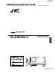
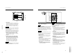
DLA-M2000LU DLA-M2000LE OPERATING INSTRUCTIONS (DLA-M2000LU / DLA-M2000LE) ® PROJECTOR FREEZE INSTRUCTIONS ENGLISH DLA-M2000LU OPERATE HIDE PRESET MENU EN R TE VIC SELECT ESCAPE PC + DIGITAL KEYSTONE VIDEO ZOOM – U T + SHIFT ZOOM FOCUS D + SHUTER – W – QUICK ALIGN. VOLUME + – RM-M2000 REMOTE CONTROL UNIT (Lenses are optional) Mar.2000 No.
IMPORTANT INFORMATION IMPORTANT SAFEGUARDS – This product is equipped with a three-wire plug. This plug will fit only into a grounded power outlet. If you are unable to insert the plug into the outlet, contact your electrician to install the proper outlet. Do not defeat the safety purpose of the grounded plug. WARNING : TO PREVENT FIRE OR SHOCK HAZARDS, DO NOT EXPOSE THIS APPLIANCE TO RAIN OR MOISTURE. CAUTION : To reduce the risk of electric shock, do not remove cover.
Contents Front Side / Top Surface / Right Side .....................6 Left-hand Side / Rear Side......................................7 Bottom Surface .......................................................8 Control Panel on the Projector ................................9 Connector Panel ...................................................11 Remote Control Unit..............................................12 Installing Batteries.................................................
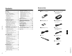
DLA-M2000LE PROJECTOR DLA-M2000LE FREEZE ENGLISH INSTRUCTIONS OPERATE HIDE PRESET MENU EN R TE VIC SELECT ESCAPE PC + DIGITAL KEYSTONE VIDEO ZOOM – U SHIFT D + SHUTER – T ZOOM + FOCUS W – QUICK ALIGN. VOLUME + – RM-M2000 REMOTE CONTROL UNIT (Lenses are optional) 1-4 No.
SAFETY PRECAUTIONS – This product should be operated only with the type of power source indicated on the label. If you are not sure of the type of power supply to your home, consult your product dealer or local power company. – This product is equipped with a three-wire plug. This plug will fit only into a grounded power outlet. If you are unable to insert the plug into the outlet, contact your electrician to install the proper outlet. Do not defeat the safety purpose of the grounded plug.
WARNING The wire which is coloured green-and-yellow must be Do not cut off the main plug from this equipment. If the plug fitted is not suitable for the power points in your home or the cable is too short to reach a power point, then obtain an appropriate safety approved extension lead or adapter or consult your dealer. connected to the terminal which is marked with the letter E or the safety earth or coloured green or green-and-yellow.
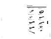
Accessories The following accessories are included with this projector. Check for them; if any item is missing, please contact your dealer. ■ Remote control unit (RM-M2000G) ■ Personal computer connection cable [approx. 2 m] (D-sub, 3-row 15 pin) ×2) ■ AA/R6-size dry cell battery (× (for checking operation) ■ AV connection cable [approx. 2 m] (for European continental countries) ■ Remote cable [approx. 3 m] (3.5 mm dia.
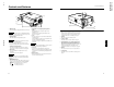
Controls and Features Left-hand Side / Rear Side EN ME EO t ME ATE LU ER VO OP ET PR NE TO E YS P HID KE p LA TEM ES ES CA PE PC VID NU TER Front Side / Top Surface / Right Side MP DLA-M2000LU DLA-M2000LE 1-8 Controls and Features 1 UP N W O D 9 MP LA HID MP TE E D BY PC PE CA ES ME ER OP LU VO AN E AT ST ET ES NE PR TO YS KE VID ME EO NU R TE EN 8 q 7 r 5 4 3 2 CAUTION • Do not block the exhaust vents, or heat will build up inside, possi
Controls and Features Controls and Features Bottom Surface Control Panel on the Projector UP DOW N LAMP HIDE NE 1 E PC ESCAPE E BY OPERAT VOLUM STAND PRESET KEYSTO TEMP t MENU VIDEO ENTER r u Opening for replacing the light-source lamp For replacing the light-source lamp, refer to “Replacing the Light-Source Lamp” on page 56.
Connector Panel 1 UP N LAMP NE MENU VIDEO ENTER 2 R PR/R-Y 8 AUDIO G Y H B PB/B-Y V 4 REMOTE 7 buttons RS-232C Use these buttons to correct a trapezoidal distortion of the projected image. (Refer to page 34.) w HIDE button Use this button to turn off the image on the screen and audio sound temporarily. Pressing it again restores the image and audio sound to resume. (Refer to page 34.) e VOLUME +/– buttons Use these buttons to adjust the sound volume: + : Increase the volume level.
Controls and Features Controls and Features q PRESET button Notes • The ZOOM T/W buttons work only if the lens unit with a zooming function is used. • The following buttons are not used with this projector. VIC SELECT, SHIFT U/D, SHUTTER e w q 1 FREEZE OPERATE HIDE MENU PRESET 2 3 EN R TE No.51781 p ESCAPE 9 + 4 VIC SELECT DIGITAL KEYSTONE VIDEO ZOOM DIGITAL KEYSTONE VIDEO ZOOM 5 LENS U T + SHIFT ZOOM FOCUS D W – QUICK ALIGN.
Installing the Projector Installing the Projector Install batteries in the remote control. If the remote control has started to work erratically, replace the batteries. Open the back cover. Open the back cover in the direction of the arrow. Precautions for using batteries If batteries are used incorrectly, they may crack or leak liquid. This could cause a fire, burn, malfunction, or staining or damaging of the surroundings. Beware of the following: 2 Install the batteries.
Installing the Projector Installing the Projector Adjusting the Inclination of the Projector Installing the Projector against the Screen The vertical angle and the leveling of the projector can be adjusted with the adjustable feet at the bottom of the projector. The projector should be placed so that the center line of the lens is at a right angle to the screen as shown in the following figures.
DLA-M2000LU DLA-M2000LE 1-14 Installing the Projector Installing the Projector Projection Distance and Screen Size Setting the Amount of Lens Shifting • The range of projection distances that can be focused depends on the lens unit (optional) to be used. When the aspect ratio of the screen is 4:3, the range is as follows and you need to install the projector within this range.
Installing the Projector Installing the Projector Effective Range and Distance of the Remote Control Unit Setting the Position Selecting Screw for Ceiling Mounting The remote control unit can be used as either a wireless remote control unit or a wired one. When using the projector in an upside-down, ceiling-mounted position (inverted top-to-bottom and right-to-left), the “position selecting screw for ceiling mounting” must be turned to switch to ceiling mounting.
Connecting to Various Devices Before connection, be sure to turn off the projector and connected devices. Read the manual which comes with each device thoroughly. ■ Allowable input signals Vertical frequency V [Hz] VESA350 640 350 37.86 PC/AT PC98 640 400 24.83 56.42 DOS/V VGA 60Hz 640 480 31.47 59.94 VGA 72Hz 640 480 37.86 72.81 VGA 75Hz 640 480 37.50 75.00 VGA 85Hz 640 480 43.27 85.01 SVGA 56Hz 800 600 35.16 56.25 SVGA 60Hz 800 600 37.88 60.
Connecting to Various Devices Connecting to Various Devices Connecting to Video Devices Connecting to Hi-Vision Devices Before connection, be sure to turn off both the projector and video device. Before connection, be sure to turn off both the projector and Hi-Vision devices. • Read thoroughly the manual that comes with each video device. • Use the supplied AV connection cable. An AV connection cable with an S-video (Y/C) terminal is not supplied.
DLA-M2000LU DLA-M2000LE 1-18 Connecting to Various Devices Connecting to Various Devices Connecting to Other Devices Connecting to Devices which Control the Projector Before connection, be sure to turn off both the projector and other devices to be connected. Before connection, be sure to turn off both the projector and devices to be connected. • Read thoroughly the manual that comes with the device to be connected. • Use the supplied AV connection cable or the cable supplied with the game device.
Connecting to Various Devices Connecting to Various Devices Connecting to Computer Devices Connecting to Computer Devices (Cont.) Before connection, be sure to turn off both the projector and computer devices. Before connection, be sure to turn off both the projector and computer devices. • Read thoroughly the manual that comes with each device. • Read thoroughly the manual that comes with each device.
Basic Operations Connecting the Power Cord ■ Projector’s buttons O VIDE ENT APE ESC PC E UME RAT VOL OPE SET PRE NE STO HIDE KEY TEM P LAM P 1 MEN U ER After all devices have been finished being connected, connect the supplied power cord. At this time, do not yet turn on the MAIN POWER switch. The following describes the basic procedure for normal use of the projector.
Basic Operations Basic Operations HIDE PC KEYSTONE VOLUME VIDEO PRESET MENU ■ Projector’s buttons To enlarge the projected screen size Press the ZOOM W (Wide) button. STAND BY LAMP TEMP OPERATE To reduce the screen size Press the ZOOM T (Tele) button. Remote control unit HIDE Y/C ↔ VIDEO PC VOLUME+/button When you press the PC button: PC1 ↔ PC2 ESCAPE ENTER Remote control unit Projector PC ■ Remote control unit PRESET PC VIDEO EN VIDEO ZOOM PRESET MENU W ESCAPE ENTER 4.
DLA-M2000LU DLA-M2000LE 1-22 Basic Operations Basic Operations ■ Projector’s buttons Turning off Image and Sound (HIDE) STAND BY LAMP TEMP OPERATE PC KEYSTONE FREEZE OPERATE HIDE VIDEO PRESET The Quick Alignment function automatically adjusts (sets) the screen settings of the image input from the PC1 or PC2 input terminals. This can only be performed from the remote control. EN Press the HIDE button again: Video image and audio sound come on again.
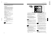
Menu Operations Basic Operations MENU EN ESCAPE button DIGITAL ZOOM +/-button R TE PRESET button VIC SELECT ESCAPE PC + DIGITAL KEYSTONE VIDEO ZOOM – T + ZOOM FOCUS D W – QUICK ALIGN. VOLUME + Cursor (5/∞/2/3)/ ENTER button When you press the FREEZE button: ■ Menu Transition Diagram in No signal Menu Mode “FREEZE” appears on the screen for a few seconds and then the still picture is shown on the screen. Refer to the FREEZE message shown on the left of this page.
Menu Operations Image adj. Image adj. Brightness Setting Contrast Color temp. Sharpness 3 or ENTER Brightness 12 Contrast 12 Sharpness 1 Color 12 Tint 12 All reset? ESCAPE Color Options Tint Language ESCAPE All reset Information All reset 5 ∞ 5 Yes ENTER Press ENTER to select an item. Press 5/∞ / 2/3 to move the video screen/menu position. Press 5/∞ to select an item. Press 2/3 to set or adjust the value.
Menu Operations Menu Operations 3 or ENTER Brightness Setting Contrast Color temp. Sharpness Brightness 12 Contrast Language 1 All reset 2 3 4 ∞ Menu ENTER Tracking Setting 3 or ENTER Phase Color temp. Tracking Position 123 Phase ENTER 12 Disp.Posi. Menu Position Options Position ENTER ESCAPE Clamp Information 5 ∞ No.51781 Menu Resize 1:1 Panel Aspect Clamp ST FP BP ENTER ESCAPE Press 2/3 to select Yes or No. Then, press ENTER to execute.
Menu Operations Basic Menu Operation Basic Menu Operation (Cont.) When the MENU button is pressed, the projector enters Video or PC menu mode by responding to the input signal being received. ■ Basic Button Functions in the Menu Mode Button Function Press the cursor button 5 or ∞ to select an item in the submenu. MENU Enters the main menu or exits the menu mode. Cursor button 5/∞ Selects an item in the menu. Pressing ∞ or 5 will scroll the item in the menu.
Menu Operations Menu Operations Changing the Color System (Video Menu Mode Only) Changing the Language Display This function is available only in Video menu mode. The menu is only displayed when there is a signal for the AV IN (Y/C and VIDEO) terminal, and not displayed when there is a signal for the PC2 terminal. Normally, use the color system in AUTO.
Menu Operations Adjusting Tracking / Phase Adjusting Picture Quality Normally, tracking and phase adjustments are automatically carried out when a video signal is input to the projector for the first time, or when the QUICK ALIGN. button on the remote control is pressed. However, you can manually adjust the tracking and phase on the menu. In the “Image adj.” submenu, adjust brightness, contrast, sharpness, etc. to obtain the desired picture quality.
Menu Operations Menu Operations Adjusting the Video Screen/Menu Position . Image adj. The position of the video screen and the menu on the video screen can be adjusted. You can finely adjust the video screen position. The menu will move widely on the video screen. All reset? Yes 1 No Press the MENU button. The main menu appears on the screen. 2 Select “Setting” with the cursor button 5 or ∞, and press 3 or the ENTER button. The “Setting 1” or “Setting” submenu appears on the screen.
Menu Operations Changing the Image Size - Resize Function (PC Menu Mode Only) The picture image projected can be selectable with the 1 Press the MENU button. Resize function which is available only in PC menu mode. You can choose the video image size projected from the following: (Factory setting is “Aspect”.) The main menu appears on the screen. The “Setting 1” submenu appears on the screen.
Menu Operations Menu Operations Setting and Adjusting Other Functions (OPTIONS) 2 or 3 Line display 2 or 3 Sets whether to show the line display (Y/C, VIDEO, PC1, or PC2) on top right of the screen or not when the VIDEO or PC button is pressed. 5sec* : Shows the line display for about 5 seconds. OFF : Does not show the line display. Select “Options” with the cursor button 5 or ∞, and press 3 or the ENTER button. ENTER Press the ENTER button to enter the keystone submenu.
DLA-M2000LU DLA-M2000LE 1-32 Replacing the Fuse Menu Operations A fuse is used to protect the power source of the projector. If the fuse is blown, replace it. When the power switch is turned on but no power is supplied to the projector, check the fuse. If there are any unclear points, contact the dealer where you purchased your projector, or consult the Service center. Getting Information You can get information on the input signal, accumulated used hours of light-source lamp, etc.
Replacing the Light-Source Lamp Replacing the Light-Source Lamp The light-source lamp has a service life of approximately 1000 hours. When the light-source lamp approaches the end of its service life, degradation progresses rapidly. The LAMP indicator and the message on the screen warn you that replacement of the lamp is required, as follows: ■ Be sure that the power cord is unplugged from the wall outlet.
Replacing the Light-Source Lamp ■ Resetting the Lamp Use Time Insert the new light-source lamp fully inside and fasten the screws. Light-source lamp After replacing with a new light-source lamp, reset the lamp-time counter inside the projector to clear the accumulated lamp time to zero (0). After resetting, a new count will start for the new light-source lamp. Fasten the two screws with a flat-end screwdriver. STANDBY indicator In stand-by mode, the STAND BY indicator on the projector lights up.
Cleaning and Replacing the Filter Cover Troubleshooting Clean the filter regularly. If the filter is heavily stained and does not clean, or if it is damaged, replace the filter with a new filter. Otherwise, dirt may get inside and appear on the screen, preventing you from fully enjoying the video image. If dirt gets inside or if you need information about the filter, consult authorized dealer where you purchased the projector or the nearest Service Center.
Probable cause • Is picture quality (color density, etc.) adjusted correctly? • Is the correct color system selected? 44 • Is the PC2 input terminal being used? • When the PC2 input terminal is being use, “PC 2(BNC)” must be selected from the menu options. Set it correctly with the input signal. 11, 52 • While computer system signal is input, isn’t a sync signal for composite sync (Cs) or G on sync being input? • Input separate sync signals for vertical sync (V) and horizontal sync (H) signals.
Warning Messages Warning Messages The following shows the warning messages that can be displayed on the screen. When a warning message is displayed, take the corrective action described here. Message PC 1 No image signal is inputted. PC 1 Cause Corrective action • Connect a device to the selected • No device is connected to the terminal. input terminal. • The terminal is connected but no • Operate the connected device and output a signal. signal is output from the connected device.
DLA-M2000LU DLA-M2000LE 1-38 RS-232C external control RS-232C external control By connecting a computer to the RS-232C terminal, you can control the projector. Use a reverse connection cable as the RS232C connection cable. The commands to control the projector and the response data against the received commands are explained here. For further information, please consult the dealer where you purchased your projector or consult the Service Center.
Appendix Appendix For lens unit GL-M2920ZG (2 to 3:1): Approximate projection distance unit: ft (m) No.51781 For 4:3 aspect-ratio screens For 16:9 aspect-ration screens 36.7” (approx. 93.2 cm) 40” (approx. 101.6 cm) 50” (approx. 127.0 cm) 60” (approx. 152.4 cm) 70” (approx. 177.8 cm) 80” (approx. 203.2 cm) 90” (approx. 228.6 cm) 100” (approx. 254.0 cm) 110” (approx. 279.4 cm) 120” (approx. 304.8 cm) 130” (approx. 330.2 cm) 140” (approx. 355.6 cm) 150” (approx. 381.0 cm) 160” (approx. 406.
® DLA-M2000LU U DLA-M2000LE U Printed in Japan LCT0941-001A/LCT0940-001A 0201-K-CR-VP PROJECTOR PROJECTOR No.