. D-ILA PROJECTOR Set up DLA-RS3000 DLA-RS2000 DLA-RS1000 Getting Started INSTRUCTIONS Operate Adjust/Set . Mobile User Guide Maintenance http://manual3.jvckenwood.com/projector/mobile/global/ The Mobile User Guide can be viewed on mobile internet devices including smartphones and tablets. . Pour utilisation par le client : Entrerci-dessous le N°de série qui est situé sous le boîtier. Garder cetteinformation comme référence pour le futur. DLA-RS3000, DLA-RS2000, Model No.
Safety Precautions Getting Started IMPORTANT INFORMATION This product has a High Intensity Dis-charge (HID) lamp that contains mercury. Manage in accord with disposal laws. Disposal of these materials may be regulated in your community due to environmental considerations. For disposal or recycling information, please contact your local authorities or for USA, the Electronic Industries Alliance: http://www.eiae.org. or call 1-800-252-5722(For USA) or 1-800-964-2650(For Canada).
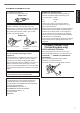
IMPORTANT SAFEGUARDS 300 mm (12 in) and above 150 mm (6 in) and above Front 300 mm (12 in) and above Getting Started Electrical energy can perform many useful functions. This unit has been engineered and manufactured to assure your personal safety. But IMPROPER USE CAN RESULT IN POTENTIAL ELECTRICAL SHOCK OR FIRE HAZARD. In order not to defeat the safeguards incorporated into this product, observe the following basic rules for its installation, use and service.
Getting Started - Do not place combustibles behind the cooling fan. For example, cloth, paper, matches, aerosol cans or gas lighters that present special hazards when over heated. - Do not look into the projection lens while the illumination lamp is turned on. Exposure of your eyes to the strong light can result in impaired eyesight. - Do not look into the inside of this unit through vents (ventilation holes), etc.
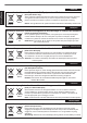
POWER CONNECTION Power cord The power supply voltage rating of this product is AC100V – AC240V. Use only the power cord designated by our dealer to ensure Safety and EMC. Ensure that the power cable used for the projector is the correct type for the AC outlet in your country. Consult your product dealer. Power cord For United Kingdom For European continent countries WARNING: Do not cut off the main plug from this equipment.
ENGLISH Getting Started Information for Users on Disposal of Old Equipment and Batteries [European Union only] These symbols indicate that equipment with these symbols should not be disposed of as general household waste. If you want to dispose of the product or battery, please consider the collection systems or facilities for appropriate recycling. Battery Products Notice: The sign Pb below the symbol for batteries indicates that this battery contains lead.
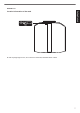
IEC62471-5 Getting Started Location information of the mark As with any bright light source, do not stare into the beam, RG2 IEC 62471-5:2015 7
Contents Getting Started Getting Started Safety Precautions .................................................. 2 Accessories/Optional Accessories .......................... 9 Check the Accessories ........................................ 9 Optional Accessories ........................................... 9 Controls and Features ........................................... 10 Main Unit - Front ................................................ 10 Main Unit - Bottom .............................................
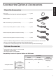
Accessories/Optional Accessories Getting Started Check the Accessories Lens cover .............................................................................. 1 piece * It is attached to the main unit at the time of shipment. Remote control ....................................................................... 1 piece AAA-size batteries (for operational check) ............................ 2 pieces Power cord (for USA) (about. 2 m (about. 78.7 in)) .................
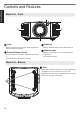
Controls and Features Getting Started Main Unit - Front B C D D A A Lens This is a projection lens. Do not look through the lens while an image is projected. B Remote Sensor (front) Please aim the remote control at this area when using it. C Indicator Refer to “Indicator Display on the Main Unit”P. 87. D Exhaust vent Warm air is discharged to cool down the internal temperature. Do not block the vents. * There is also a remote sensor at the rear.
F Lamp Cover When replacing the light source lamp, remove this cover. (P. 67) F Main Unit - Rear G H I K K J G Input terminals In addition to the video input terminal, there are also other connection terminals for devices such as controllers and optional equipment. Please see “Main Unit - Input Terminals”P. 12 for more details about the terminals. H Operation panel For more details, please refer to the “Operation panel” in the diagram below.
Operation panel Getting Started [J INPUT K]: Switches the input A: Turns “on”/“off” the power [BACK]: Returns to the previous menu [MENU]: Displays the menu [OK]: Confirms a selection [JKH I] keys: Selects an item Main Unit - Input Terminals A B C A [3D SYNCHRO] terminal By connecting a 3D Synchro Emitter (sold separately) to this terminal, you can view 3D movies. B [HDMI 1] input terminal C [HDMI 2] input terminal For connecting to devices that support HDMI output. (P.
A B [STANDBY] Turns off the power. (P. 23) B C [ON] M [COLOR PROFILE] Switches the input to [HDMI 1] or [HDMI 2]. (P. 22) N [GAMMA SETTINGS] Displays the installation mode selection menu. O [C.M.D.] For adjusting focus, zoom, and shift. (P. 24) Pressing the button each time switches the setting in the following sequence: “Focus” " “Zoom” " “Shift”... P [MPC] B C [INPUT] F G D [SETTING MEMORY] E [LENS CONTROL] H I K J L M O P R 0 Displays the picture mode selection menu. (P.
Getting Started Loading Batteries into the Remote Control Loading the batteries 0 0 0 Removing the batteries If the remote control has to be brought closer to the unit to operate, it means that the batteries are wearing out. Replace the batteries with new ones (AAA). Insert the batteries according to the t s marks. Be sure to insert the s end first. When removing the battery, do so from the t end. If an error occurs while using the remote control, remove the batteries and wait for five minutes.
A B C D E F Select the icon at the top of the menu to display its corresponding setting item as shown below.
Installing the Projector Precautions during Installation Please read the following carefully before installing this unit. When carrying this unit Do not install at the following 5° 5° 10° Vertical inclination: within ± 10 ° 0 10° Maintain clearance from the wall, etc. As the unit discharges a large amount of heat, install it with adequate clearance from the surroundings as shown below.
Precautions during Mounting Securing (mounting) the projector When this unit is to be mounted to a fixed position for use, install it horizontally. 0 Make sure to secure the main unit to prevent accidents such as during an earthquake. 0 Be sure to ask your dealer to install the unit for you. Installing the unit on your own may cause the unit to fall resulting in injury. 0 Take the necessary actions to prevent the main unit from falling off such as during an earthquake.
Adjusting the Position Adjusting the elevation angle of the projector The height and inclination of the unit (0 to 5 mm (0 to 0.2 in)) can be adjusted by turning the feet. Lift the unit and adjust the four feet. 4 Locations Set up Extend Contract Feet Adjusting the position of the image By using the lens shift feature of this unit, you can shift the image upward/downward or to the left/right. Set it to your preferred position. Æ “Adjusting the Lens According to the Projection Position” (P.
Connecting the Projector 0 Do not turn on the power until connection is complete. 0 The connection procedures differ according to the device used. For details, please refer to the instruction manual of the device to be connected. 0 This projector is used for projecting images. To output the audio of connected devices, please connect a separate audio output device, such as an amplifier or speaker. 0 The images may not be displayed depending on the devices and cables to be connected.
Connecting via HDMI-DVI conversion cable Desktop PC, etc. This Unit To [HDMI 1] or [HDMI 2] input terminal Set up DVI Output Terminal HDMI-DVI Conversion Cable (Sold Separately) 0 If noise occurs, move the desktop PC away from this unit. 0 If the video is not displayed, try to reduce the length of the cable or lower the resolution of the video transmitting equipment. Connecting to the LAN Terminal Hub This Unit Desktop PC, etc.
Connecting to the TRIGGER Terminal Screen This Unit Set up To [TRIGGER] Terminal Trigger Input Terminal (Ø3.5) Trigger Cable (Sold Separately) 0 Do not use it to supply power to other devices. 0 Connecting to the audio terminal of another device may cause the device to malfunction or break down. 0 Using beyond the rated value will cause the unit to malfunction. 0 The trigger terminal outputs a voltage of 12 V. Exercise adequate caution to prevent short circuit. 0 The factory setting is “Off”.
Viewing Videos MEMO 0 Make sure to remove the lens cover. 0 Connect the power cord, and ensure that the “STANDBY/ON” indicator lights up in red. 0 During standby in the “ECO Mode”, the “STANDBY/ON” indicator does not light up even when the power cord is correctly connected. In this case, cancel the standby mode by pressing any button on the remote control unit, or use the A button on the projector unit when you are turning on the power.
3 Turn off the power Remote control: press the B [STANDBY] button Projector unit: press the A button 0 While the “Are you sure you want to turn off?” message is displayed, press the button again. 0 The lamp turns off, and the “STANDBY/ON” indicator switches from a green light to a red blinking light. 0 After the light goes off, the fan will run for about 60 seconds to cool down the lamp (Cool-down mode). Do not disconnect the power cable while cooling is in progress.
Adjusting the Projector Screen Adjusting the Lens According to the Projection Position 1 Press the [LENS CONTROL] button, and use the [JKH I] keys to adjust Focus, Zoom (screen size), and Shift (screen position) 1 Focus 2 Operate 0 Pressing the [LENS CONTROL] or [OK] button each time switches the mode in the following sequence: “Focus” " “Zoom” " “Shift” " “Focus”... 0 Operation of the lens control feature is disabled when the lens lock is set to “On”. (P.
Setting Screen Correction 1 Set Screen Adjust By selecting the optimal correction mode according to the characteristics of the screen in use, corrections can be performed to reproduce natural images with balanced colors. Screen Adjust Screen Adjust Screen No. Off 0 1 8 This item is not available when “Color Profile” is set to “Off”. 0 For information on the screen and the corresponding correction mode, please visit our website.
Adjusting the Screen Size (Aspect) The screen size of the projected image can be adjusted optimally according to the original screen size (aspect) that has been input.
Viewing 3D Movies By using the 3D Glasses (PK-AG1, PK-AG2, or PK-AG3) and 3D Synchro Emitter (PK-EM1 or PK-EM2), both sold separately, you can enjoy 3D video images. 0 For 3D Glasses and 3D Synchro Emitter that are compatible with this unit, please refer to “Optional Accessories”P. 9.
Viewing 3D Movies 1 Connect this unit to a 3D-compatible HDMI device, and turn on the power to play back the 3D video image 0 0 For details on how to play back 3D video images, please refer to the instruction manual of the player or recorder in use. This unit supports the following 3D formats.
Selecting an Image Quality According to the Video Type Setting the Picture Mode You can adjust the image quality according to the type of video image you are viewing. 1 Press the [PICTURE MODE] button, use the [JK] keys to select “Picture Mode” and press [OK] 0 You can configure more detailed setting items by pressing the [MENU] button to display the menu, followed by selecting “Picture Adjust” " “Picture Mode” and pressing the [OK] button. (P.
Setting the Color Profile By setting the “Color Profile” (color space information) according to the “Picture Mode”, you can fine-tune the image quality according to the movie you are viewing. * This item is not available when “Picture Mode” is set to “Frame Adapt HDR”. 1 After configuring “Picture Mode” (P.
List of selectable “Color Profile” according to “Picture Mode” Picture Mode Natural Color Profile BT.709 BT.2020 r s DCI Video Anime. r s HDR Cinema BT.709 BT.2020 r s Cinema DCI Video HDR HDR10 HLG BT.709 BT.2020 r s DCI HDR Film r s Film 1 Film 2 THX BT.709 Adjust/Set THX r User 1 to User 6 BT.2020 r s DCI Video Anime. r s Cinema HDR Off Custom1 to Custom4 Pana_PQ_HL* Pana_PQ_BL* * Color profile for Panasonic UHD BD player only. For details on how to use these options, please refer to P. 35.
Adjusting to your Preferred Color (Color Management) Based on the setting of the selected “Color Profile”, you can adjust each of the following colors according to your preference: Red, Yellow, Green, Cyan, Blue, and Magenta.
Viewing HDR Contents When viewing HDR contents, making adjustments according to the content and viewing environment allows the images to be played back in higher quality. What is HDR content? HDR (High Dynamic Range) refers to images with a significant difference in brightness between the highlight and shadow areas (dynamic range).
Auto Tone Mapping Grading varies diversely with the video work, with some content being made brighter and others darker. By using the “Auto Tone Mapping” function, gamma adjustment is performed automatically to achieve the optimal picture performance based on the mastering information (Max CLL/Max FALL) contained in the HDR10 content. Also, by configuring the base brightness level in “Mapping Level”, you can enjoy the optimal picture quality according to the screen size and viewing environment.
Collaboration with Panasonic UHD BD Player DP-UB9000 Selecting one of two special projector color profiles from the HDR Display Type of the DP-UB9000 enhances dimensionality and improves gradation accuracy by tone mapping HDR video to match the JVC projector display characteristics. * Supports firmware version v2.00 or later. Step 1: Using Panasonic DP-UB9000: Select “High Luminance Projector” or “Basic Luminance Projector” from HDR Display Type Setting.
Adjusting Movies for Increased Expressiveness (Multiple Pixel Control) The new image-processing algorithm developed by JVC helps to create a natural impression that is sharper at areas in focus, and softer at areas that are not in focus, enabling you to enjoy highly expressive images with a greater sense of depth. 1 Press the [MPC] button to display the adjustment menu 0 The setting can also be configured by selecting “Picture Adjust” " “MPC/e-shift” r, “MPC Level” s t from the menu.
Fine-tuning the Image Quality Adjusting the Output Value of the Projected Image (Gamma) You can adjust the output value of the projected image with respect to the video signal input. * This item is not available when “Picture Mode” is set to “Frame Adapt HDR”. Example of gamma adjustment Output Value The overall image appear brighter with respect to the original image, making the dark areas more visible. A B 255 B A 0 0 Input Value 255 The photos are for illustrative purposes only.
“Gamma” Gamma Description When “Color Profile” is Film 1 set to “Film 1”r s Film 2 Image is close to the characteristics of Eastman Kodak Company movie films. When “Color Profile” is Film 1 set to “Film Film 2 2”r s Places more emphasis on the contrast compared to the “Film 2” setting. 2.2 The gamma is set to “2.2”, “2.4” and “2.6” respectively. Places more emphasis on the gradation compared to the “Film 1” setting. Image is close to the characteristics of FUJIFILM Corporation movie films. 2.4 2.
Fine-tuning to the Preferred Gamma Setting You can perform fine adjustments based on the selected gamma adjustment setting. 1 Press the [GAMMA SETTINGS] button to display the gamma menu 0 2 You can also perform setting from “Picture Adjust”"“Gamma” in the menu. Adjust to the preferred setting 0 Select the color to be adjusted from “Color Selection” and adjust the “Picture Tone”, “Dark Level” and “Bright Level”.
Selecting the Base Correction Value (Initial Value) for Adjustment 0 Selecting one of the “Custom 1” to “Custom 3” settings in “Gamma” allows you to select the “Correction Value”. Select the base “Correction Value” for adjustment using the H I keys. 0 The selectable correction values vary according to “Picture Mode”. (Refer to the table below.
Gamma Adjustment 0 Gamma Curve Bright 255 0 Output Value A 0 D” D Dark B 0 0 0 Dark 255 C Input Value When the gamma curve is a straight line: The brightness and contrast of the video input will be the same as that of the video output. Area for which the gamma curve is above the straight line (A): Video output appears brighter than the input. Area for which the gamma curve is below the straight line (B): Video output appears darker than the input.
Configure to “HDR Processing” in the “Picture Adjust” menu. *3 3 “HDR Processing” This is a feature for configuring the method of content analysis. HDR Processing Effects on the Video Image Frame by Frame Automatically adjusts the HDR tone mapping after analyzing the peak brightness of each frame. Scene by Scene Automatically adjusts the HDR tone mapping after analyzing the peak brightness of each scene.
Setting Auto Tone Mapping * This item is not available when “Picture Mode” is set to “Frame Adapt HDR”. 1 Press the [GAMMA SETTINGS] button to display the gamma menu Gamma Max CLL/Max FALL 1000 / 400 nits Gamma HDR(PQ) --- Correction Value Auto Tone Mapping 2 Set “Auto Tone Mapping” to “On” 0 3 The “Auto Tone Mapping” menu is displayed when “Gamma” is set to “HDR(PQ)” during playback of HDR contents, or when “Correction Value” of Gamma is set to “HDR(PQ)”.
Using Tone Mapping for Manual Adjustments “HDR(PQ)” gamma is the PQ curve adopted by HDR10. Fine adjustments can be made according to the screen size and environment although the default settings for viewing with the projector have been adjusted to allow optimum viewing. Default settings when viewing HDR contents of this projector Picture Mode Gamma Estimated Screen Size Estimated MaxCLL/ MaxFALL : : : : HDR10 HDR(PQ) 90 to 120 inch (screen gain 1.
For users seeking to obtain a gamma curve that is more faithful to the original PQ curve Our projectors have been adjusted to display the projector images on the screen in the optimal quality in the default setting based on the original PQ curve. For users who wish to obtain results more faithful to the original PQ curve, please adjust manually with reference to the values below.
Clear Motion Drive (C.M.D.) Optimal interpolation according to the content is made possible with the new high-definition image interpolation technique. For some scenes, interpolation may cause distortion in the image. In this case, set to “Off”. Original Image Interpolation Enabled Intermediate Frame Generation 1 Press the [C.M.D.
Adjustments and Settings in the Menu Pressing the [MENU] button displays the menu. Press the [JKH I] keys to select an item, followed by pressing the [OK] button to confirm the selection. List of Menu Items Picture Adjust Mode .................................................................................................................................................... P. 29 9 Lamp Power ....................................................................................................................
Installation Mode .............................................................................................................................................. P. 56 Control ..................................................................................................................................................... P. 24 9 Focus .......................................................................................................................................................... P. 24 9 Zoom .....
Picture Adjust Picture Mode You can adjust the image quality according to the type of video image you are viewing. Æ “Setting the Picture Mode” (P. 29) You can configure the following setting items by pressing the [MENU] button to display the menu, followed by selecting “Picture Adjust” " “Picture Mode” and pressing the [OK] button. Lamp Power Switches the brightness of the lamp. Setting Description Low Brightness (low) High Brightness (high) 0 0 The factory setting varies with the “Picture Mode”.
Color Profile By setting the “Color Profile” (color space information) according to the “Picture Mode”, you can fine-tune the image quality according to the movie you are viewing. Æ “Setting the Color Profile” (P. 30) * This item is not available when “Picture Mode” is set to “Frame Adapt HDR”. Color Management Each of the colors is adjustable according to the user’s preference. Æ “Adjusting to your Preferred Color (Color Management)” (P. 32) Color Temp.
List of selectable “Color Temp.” according to “Picture Mode” Picture Mode Film r s Color Temp. Xenon 1 r s Xenon 2 r s Custom 1 to Custom 2 Cinema 5500K 6500K 7500K 9300K Xenon 1 r s Xenon 2 r s High Bright HDR10 HLG Custom 1 to Custom 2 Natural HDR10 HLG User 1 to User 6 Frame Adapt HDR* 5500K 6500K 7500K 9300K High Bright HDR10 Adjust/Set HLG Custom 1 to Custom 2 THX r 6500K * Supports software version v3.10 and later versions.
List of selectable “Correction Value” according to “Picture Mode” Picture Mode Film r s Correction Value Xenon 1 r s Xenon 2 r s Cinema 5500K 6500K 7500K 9300K Xenon 1 r s Xenon 2 r s High Bright Natural HDR10 HLG User 1 to User 6 Frame Adapt HDR* 5500K 6500K 7500K 9300K High Bright * Supports software version v3.10 and later versions. Gamma Adjust/Set You can adjust the output value of the projected image with respect to the video signal input.
MPC/e-shift r, MPC Level s t You can enjoy natural, expressive images with a stronger sense of depth. Æ “Adjusting Movies for Increased Expressiveness (Multiple Pixel Control)” (P. 36) 8K e-shift r Switches the display resolution. 0 Setting values: On (8K), Off (4K) Graphic Mode Switches the MPC setting. It is recommended that this item be configured to “Standard” such as when viewing normal Blu-ray contents, and to “High-res” such as when viewing 4K resolution contents.
Input Signal Input Level For setting the dynamic range (gradation) of the video input. If the image is not displayed properly even after selecting “Auto”, select an appropriate setting. 0 If the dynamic range is not appropriate, the bright areas become overexposed, and the dark areas become underexposed. Setting Description Auto Sets the input signal level automatically. 16-235 (Video) Select this setting if you are inputting video signals (dynamic range: 16 - 235).
HDR Setting HDR10 Auto Select For configuring the automatic switching setting of “Picture Mode” when receiving HDR10 packets. Setting Description HDR10 Automatically switches “Picture Mode” to “HDR10” when receiving HDR10 packets. Frame Adapt HDR* Automatically switches “Picture Mode” to “Frame Adapt HDR” when receiving HDR10 packets. User 1 to User 6 Automatically switches “Picture Mode” to User 1 to User 6 when receiving HDR10 packets.
Installation Installation Mode Collectively manages the setting values of “Lens Control”, “Pixel Adjust”, “Mask”, “Anamorphic”, “Screen Adjust”, “Installation Style”, “Keystone”, “Pincushion” and “Aspect”. * The lens position may be shifted slightly with respect to the position that was saved. * Software version v3.10 and later versions do not support “Pincushion”. Mode Select For selecting the group to save and retrieve the setting values.
Lens Control Focus / Zoom / Shift For adjusting the lens according to the projection position Æ “Adjusting the Lens According to the Projection Position” (P. 24) Image Pattern For setting whether to display the lens adjustment pattern. Setting Description Off Displays external signals, and does not display the lens adjustment pattern. On Displays the lens adjustment pattern. Lock For setting whether to lock or unlock the lens.
Pixel Adjust For correcting the phase shifting between each RGB color by adjusting the pixel. Adjust For setting the adjustment feature to On or Off. Adjust Area Setting Description Whole Adjusts the entire image. Zone Enables fine adjustment of each area by dividing the screen evenly into 10 vertical and horizontal zones. Adjust Color For selecting the color to adjust (“Red” or “Blue”).
Whole Adjust (Pixel) Operation Procedure For making general adjustments to slight color fringing in the horizontal/vertical directions of the video image. A Set “Adjust Area” to “Whole” B Select “Adjust Color” and “Adjust Pattern Color” C Select “Adjust (Pixel)”, and press the [OK] button 0 The Adjustment mode is activated, and the selected adjustment pattern and Adjustment (Pixel) window are displayed.
Whole Adjust (Fine) Operation Procedure For making general adjustments on the misalignment of the entire screen using “Adjust (Pixel)”, followed by making fine adjustments. A Set “Adjust Area” to “Whole” B Select “Adjust Color” and “Adjust Pattern Color” C Select Adjust (Fine), and press the [OK] button 0 The Adjustment mode is activated, and the selected adjustment pattern and Fine window are displayed. 0 The adjustable range may be smaller depending on the pixels being adjusted on the entire screen.
Zone Adjust Operation Procedure For fine-tuning misalignments on a part of the screen after adjusting the overall screen misalignment using “Adjust (Pixel)” and “Adjust (Fine)”. 0 The screen can be divided vertically and horizontally into 10 sections for partial adjustments to be made.
Mask For hiding the peripheral area of the image with a mask (black strip). Setting Description Off Not masked. On Hides the ranges specified in “Top”, “Bottom”, “Left” and “Right” by masking (with black strips). Off On Mask: black strip around the periphery “Top” / “Bottom” / “Left” / “Right” For specifying the ranges to hide by masking (with black strips). 0 Setting range: 0 to 220 Anamorphic Configure this setting when an anamorphic lens is used.
Keystone For correcting any keystone distortion that occurs when the projector is installed at an angle with respect to the screen. 0 Vertical setting range: -16 to +16 * Increasing the value changes the aspect slightly. * This function cannot be used if “Pincushion” is set. -16 16 0 Pincushion Corrects the geometric distortion that occurs when projecting on a curved screen.
Logo For setting the display of logo during startup to “On” or “Off”. Setting Description Off Not displayed. On Displays the “D-ILA” logo for 5 seconds during startup. Language For setting the display language to “English”, “Deutsch”, “Español”, “Italiano”, “Français”, “Português”, “Nederlands”, “Polski”, “Norsk”, “Русский”, “中文”, “繁體中文”, or “日本語”. Function Trigger For setting whether to supply a 12 V output to devices such as an external screen equipped with a trigger function.
Network For specifying the settings for external control from a PC or smartphone. Setting DHCP Client Description On Obtains the IP address automatically from the DHCP server inside the connected network. Off For configuring the network settings manually. IP Address For configuring the IP address. Subnet Mask For configuring the subnet mask. Default Gateway For configuring the default gateway. MAC Address Displays the MAC address of the unit. Set Applies the network settings.
High Altitude Mode For setting the high altitude mode to “On” or “Off”. Set to “On” when using the projector at a location of low atmospheric pressure (higher than 900 m (3,000 ft) above sea level). Factory Reset For restoring the settings of this unit to the factory default. However, the following settings will not be reset. 0 Gamma data saved in “Gamma” " “Correction Value” " “Import”. 0 Color profile data saved in “Color Profile” " “Custom1 to Custom6”.
Replacing the Lamp The lamp is a consumable item. If the image appears dark or the lamp goes out, replace the lamp unit. 0 When the lamp replacement time approaches, the user is notified with a message displayed on the screen and by the indicator. (P. 87) Lamp Replacement Procedure CAUTION 0 Do not insert your hands into the lamp compartment. This could cause significant deterioration in the performance of the equipment, or lead to injury and electric shock.
6 Tighten the screws of the new lamp unit 0 Tighten the screws with a t screwdriver. MEMO Usable lamp life 0 When the lamp is used with “Lamp Power” set to “Low”, the lamp life on this unit is approximately 4500 hours. This is the average usable time and not a guaranteed value. 0 The lamp life may not reach 4500 hours depending on the operating conditions. 0 When the lamp has reached the end of its usable life, deterioration progresses rapidly.
Resetting the Lamp Time Reset the lamp time when you have replaced the lamp.
Maintaining the Cabinet and Remote Control 0 Gently wipe off dirt on the cabinet with a soft cloth. 0 If it is extremely dirty, wet a cloth in water, wring dry and use it to wipe off the dirt, followed by wiping again with a dry cloth. 0 Pay attention to the following as the cabinet may deteriorate in condition or the paint may come off.
Troubleshooting Before sending the unit to your authorized dealer for repair, please check the following points. The following symptoms are not malfunctions. You do not need to worry about the following symptoms if there is no abnormality on the screen. 0 A part of the top or front surface of the unit is hot. 0 A creaking sound is heard from the unit. 0 An operating sound is heard from the inside of the unit. 0 Color smear occurs on some screens. This unit is a digital device.
Video image does not appear Check Action Refer to Is the correct external input selected? Select the correct external input terminal. P. 22 Is the power of the AV device or PC turned on? Turn on the power of the AV device or PC and play the video. P. 19 Is the AV device or PC properly connected? Connect the AV device or PC properly. P. 19 Are the correct signals being output from Set the AV device or PC properly. the AV device or PC? P. 19 Is the cable in use an HDMI-certified cable? P.
Video image looks unnatural Colors are unnatural Check Action Refer to Is the color space of the input signal correctly set? The color may turn out unnatural when the input signal is P. 54 different from that in the projector setting. Set the “Color Space” for “Input Signal” correctly. Is the image correctly adjusted? Adjust “Color” and “Tint” accordingly. P. 53 Is the AV device or PC properly connected? Connect the AV device or PC properly. P.
Striped patterns appear on the screen Check Does the fabric of the screen have a regular pattern? Action Refer to Interference fringes may sometimes occur between the fabric pattern and the pixels. Please consult the authorized dealer. — Action Refer to Video images are missing Check Has screen mask been configured? Set “Mask” to “Off”. P. 62 Remote control does not work Check Action Refer to Are the batteries correctly loaded? Match the polarities (t s) correctly when loading the batteries.
When the Following Messages Appear... Message Description 0 No device is connected to the input terminal. 0 The input terminal is connected but there is no signal. No Input Action Input the video signals. The video signal input is not supported Input video signals that can be used. on this unit. (P. 86) Out of Range Lamp replacement Back BACK Indicates that the lamp needs to be Get ready a new lamp unit and replace replaced soon. as soon as possible.
External Control It is possible to control this unit by connecting it to a PC using an RS-232C cross cable (D-sub 9-pin). The projector can be controlled by connecting it to a PC through the computer network with a LAN cable for control commands to be sent to the projector. Æ “Network” (P. 65) 0 Please use it after you have gained proper understanding from professional books or consulting the system administrator. RS-232C Specifications This Unit Pin No.
Command Format The command between this unit and the computer consists of “Header”, “Unit ID”, “Command”, “Data” and “End”. 0 Header (1 byte), Unit ID (2 bytes), Command (2 bytes), Data (n bytes), End (1 byte) Header This binary code indicates the start of communication.
Remote Control Code Binary code is sent during communication. Remote Control Button Name Binary Code Remote Control Button Name Binary Code STANDBY 37 33 30 36 OK 37 33 32 46 ON 37 33 30 35 MENU 37 33 32 45 INPUT 37 33 30 38 BACK 37 33 30 33 SETTING MEMORY 37 33 44 34 PICTURE MODE 37 33 46 34 LENS CONTROL 37 33 33 30 COLOR PROFILE 37 33 38 38 HIDE 37 33 31 44 GAMMA SETTINGS 37 33 46 35 INFO. 37 33 37 34 C.M.D.
Communications Example This section shows the communication examples of RS-232C.
Specifications Product Name D-ILA Projector Model Name DLA-RS3000, DLA-RS2000, DLA-RS1000 Display Panel/Size D-ILA device *1, 2 0.69” 4K D-ILA (4096 x 2160 pixels) x 3 Projection Lens 2.0 x power zoom lens, motorized zoom and focus Light-source Lamp 265 W ultra-high pressure mercury lamp [product no.: PK-L2618UW Average lifespan: 4500 hours (“Low” mode) Screen Size Approx. 60” to 280” (Aspect ratio of 16:9) r Approx.
r has obtained the “THX 4K DISPLAY Certification” determined by THX Ltd. In addition to 2K content, you can also enjoy faithful reproduction of images in a quality as intended by the filmmaker during playback of 4K content. The THX 4K DISPLAY certification is “an indication of high definition and high resolution”, which is granted to products that have cleared more than 400 image quality tests. ® This unit is isf-certified, so calibration can be performed by an isf-certified trainer.
Screen Size and Projection Distance r Screen Size Diagonal (Inch) Projection Distance (m) 17:9 Screen 16:9 Screen 2.35:1 Screen 4:3 Screen Wide-end Tele-end Wide-end Tele-end Wide-end Tele-end Wide-end Tele-end 60 1.67 3.43 1.75 3.61 1.86 3.82 2.16 4.44 70 1.96 4.02 2.06 4.23 2.18 4.47 2.54 5.19 80 2.25 4.60 2.37 4.84 2.50 5.12 2.91 5.94 90 2.54 5.19 2.67 5.46 2.83 5.77 3.29 6.70 100 2.83 5.77 2.98 6.07 3.15 6.41 3.66 7.45 110 3.12 6.36 3.28 6.69 3.
Screen Size Diagonal (Inch) Projection Distance (Inch) 17:9 Screen 16:9 Screen 2.35:1 Screen 4:3 Screen Wide-end Tele-end Wide-end Tele-end Wide-end Tele-end Wide-end Tele-end 60 65.5 135.1 69.1 142.2 73.1 150.3 85.2 174.7 70 77.0 158.2 81.1 166.4 85.8 175.8 100.0 204.3 80 88.5 181.2 93.1 190.6 98.5 201.4 114.7 234.0 90 99.9 204.2 105.2 214.8 111.2 227.0 129.5 263.6 100 111.4 227.3 117.2 239.0 123.9 252.5 144.2 293.2 110 122.8 250.3 129.3 263.3 136.
s/t Screen size Diagonal (Inch) Projection Distance (m) 17:9 Screen 16:9 Screen 2.35:1 Screen 4:3 Screen Wide End Tele End Wide End Tele End Wide End Tele End Wide End Tele End 60 1.79 3.66 1.88 3.85 1.99 4.07 2.31 4.73 70 2.09 4.28 2.20 4.50 2.33 4.76 2.70 5.52 80 2.40 4.90 2.52 5.15 2.67 5.44 3.10 6.32 90 2.70 5.52 2.84 5.80 3.00 6.13 3.49 7.11 100 3.01 6.14 3.16 6.45 3.34 6.81 3.88 7.91 110 3.31 6.75 3.49 7.10 3.68 7.50 4.28 8.70 120 3.
Screen Size Diagonal (Inch) Projection Distance (Inch) 17:9 Screen 16:9 Screen 2.35:1 Screen 4:3 Screen Wide-end Tele-end Wide-end Tele-end Wide-end Tele-end Wide-end Tele-end 60 70.5 144.1 74.0 151.6 78.3 160.2 90.9 186.2 70 82.3 168.5 86.6 177.2 91.7 187.4 106.3 217.3 80 94.5 192.9 99.2 202.8 105.1 214.2 122.0 248.8 90 106.3 217.3 111.8 228.3 118.1 241.3 137.4 279.9 100 118.5 241.7 124.4 253.9 131.5 268.1 152.8 311.4 110 130.3 265.7 137.4 279.
Types of Possible Input Signals Video Digital Video Signal 480p 576p 720p 50/60 Hz 1080i 50/60 Hz 1080p 24/25/30/50/60 Hz 2K (2048×1080) 24/25/30/50/60 Hz 4K (3840x2160) 24/25/30/50*/60* Hz 4K (4096x2160) 24/25/30/50*/60* Hz 3D Signal Frame Packing 720p 50/60 Hz 1080p 24 Hz Side-by-side 720p 50/60 Hz 1080p 50/60/24 Hz 1080i 50/60 Hz Top-and-bottom 720p 50/60 Hz 1080p 24 Hz * When the color space is RGB/YCbCr(4:4:4), only 8-bit input is supported.
Indicator Display on the Main Unit Meaning of the front panel indicators The indicator is solid. The indicator appears blinking. Operation mode display Displays using the different colors and solid/blinking light of the indicator on the projector unit.
Warning display You can tell the details of a warning from the (repeated) displays of the “WARNING” and “LIGHT” indicators. The “STANDBY/ON” indicator will light up or appear blinking according to the operation mode of the projector unit. (Please refer to ““Operation mode display”P. 87”.) The Warning mode is activated once the message is displayed. Projection is interrupted, and the cooling fan is turned on for about 60 seconds. The power cannot be turned on again while cooling is in progress.
Dimensions (Unit: mm (in)) r Top Surface Bottom Surface 290 (11-7/16) 23 (15/16) 69 (2-3/4) 145 (5-11/16) 518 (20-3/8) 337 (13-1/4) 500 (19-3/4) 37 (1-7/16) Rear Surface 71 (2-13/16) 243 (9-19/32) 107 (4-7/32) 33 (1-5/16) 329 (12-15/16) 71 (2-13/16) 20 (13/16) 104 (4-1/16) 234 (9-1/4) 98 (3-7/8) 98 (3-7/8) 79 60 (3-1/8) (2-3/8) Front 41 (1-5/8) 211 (8-5/16) Others 89
s/t Top Surface Bottom Surface 290 (11-7/16) 46 (1-13/16) 122 (4-13/16) 495 (19-1/2) 337 (13-1/4) 500 (19-3/4) Front 41 (1-5/8) Rear Surface 71 (2-13/16) 98 (3-7/8) 79 60 (3-1/8) (2-3/8) 243 (9-19/32) 107 (4-7/32) 33 (1-5/16) 329 (12-15/16) 71 (2-13/16) 20 (13/16) 104 (4-1/16) 234 (9-1/4) 98 (3-7/8) Others 90 37 (1-7/16) 211 (8-5/16)
Index A Accessories............................................................ 9 Adjusting Distortion of the Projection Screen........ 24 Adjusting the Position........................................... 18 Adjustments and Settings in the Menu..................47 Anamorphic ..........................................................62 Aperture ............................................................... 49 Aspect ..................................................................26 Auto Tone Mapping .....
Types of Possible Input Signals............................ 86 U User Name Edit ....................................................49 V Viewing 3D Movies............................................ 000 Viewing HDR Contents......................................... 33 Viewing Videos..................................................... 22 W When the Following Messages Appear.................75 Whole Adjust (Fine) ........................................58, 60 Whole Adjust (Pixel) .............................
Others 93
. 0922KSH-XX-XX © 2019 DLA-RS3000 DLA-RS2000 DLA-RS1000 D-ILA PROJECTOR .