ENGLISH FRANÇAIS ESPAÑOL/CASTELLANO DILA PROJECTOR Set up DLARS66 DLARS56 DLARS48 DLARS46 Getting Started INSTRUCTIONS Operate Adjust/Set Maintenance Instrucción para el cliente : Introduzca a continuación el nº de serie que aparece en la parte inferior lateral de la caja. Conserve esta información como referencia para uso ulterior. Model No.
Safety Precautions Getting Started IMPORTANT INFORMATION This product has a High Intensity Dis-charge (HID) lamp that contains mercury. Disposal of these materials may be regulated in your community due to environmental considerations. For disposal or recycling information, please contact your local authorities or for USA, the Electronic Industries Alliance: http://www.eiae.org. WARNING: TO PREVENT FIRE OR SHOCK HAZARDS, DO NOT EXPOSE THIS APPLIANCE TO RAIN OR MOISTURE.
IMPORTANT SAFEGUARDS - All the safety and operating instructions should be read before the product is operated. - The safety and operating instructions should be retained for future reference. - All warnings on the product and in the operating instructions should be adhered to. - All operating instructions should be followed. - Place the projector near a wall outlet where the plug can be easily unplugged. - Unplug this product from the wall outlet before cleaning.
Getting Started - Do not place combustibles behind the cooling fan. For example, cloth, paper, matches, aerosol cans or gas lighters that present special hazards when over heated. - Do not look into the projection lens while the illumination lamp is turned on. Exposure of your eyes to the strong light can result in impaired eyesight. - Do not look into the inside of this unit through vents (ventilation holes), etc.
POWER CONNECTION Power cord The power supply voltage rating of this product is AC110V – AC240V. Use only the power cord designated by our dealer to ensure Safety and EMC. Ensure that the power cable used for the projector is the correct type for the AC outlet in your country. Consult your product dealer.
ENGLISH Getting Started Information for Users on Disposal of Old Equipment and Batteries [European Union only] These symbols indicate that equipment with these symbols should not be disposed of as general household waste. If you want to dispose of the product or battery, please consider the collection systems or fa cilities for appr opriate recycling. Battery Products Notice: The sign Pb below the symbol for batteries indicates that this battery contains lead.
ITALIANO Getting Started Informazioni per gli utenti sullo smaltimento delle apparecchiature e batterie obsolete [Solo per l’Unione Europea] Questi simboli indicano che le apparecchiature a cui sono relativi non devono essere smaltite tra i rifiuti domestici generici. Se si desidera smaltire questo prodotto o questa batteria, prendere in considerazione i sistem i o le strutture di raccolta appropriati per il riciclaggio corretto.
SVENSKA Getting Started Information för användare gällande bortskaffning av gammal utrustning och batterier [Endast den Europeiska unionen] Dessa symboler indikerar att utrustning med dessa symboler inte ska hanteras som vanligt hushållsavfall. Om du vill bortsk affa produkten eller batteriet ska du använda uppsamlingssystem eller inrättningar för lämplig återvinning. Batteri Produkter Observera: Märkningen Pb under symbolen för batterier indikerar att detta batteri innehåller bly.
MAGYAR Getting Started Felhasználói információ az elhasznált be rendezések és akkumulátorok elhelyezéséről [Csak az Európai Unióban] Ez a szimbólum azt jelzi, hogy a berendezés nem helyezhető az általános háztartási hulladék közé. Ha meg szeretne szabadulni a terméktől vagy az akkumulátortól, akkor legyen tekintettel az gyűjtő rendszerre vagy intézményekre a megfelelő hasznosítás érdekében.
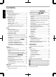
Contents Getting Started Getting Started Safety Precautions .................................................. 2 Accessories/Optional Accessories ........................ 11 Check the Accessories ...................................... 11 Optional Accessories ......................................... 11 Main Features ....................................................... 12 Controls and Features ........................................... 14 Main Unit Front ..............................................
Accessories/Optional Accessories Getting Started Check the Accessories Lens cover .............................................................. 1 piece *It is attached to the main unit at the time of shipment. Remote control ....................................................................... 1 piece AAAsize batteries (for operational check) ............................ 2 pieces Power cord (for USA) (about. 2 m) ......................................... 1 piece Power cord (for UK) (about.
Main Features Getting Started Highdefinition 4K display that surpasses full HD quality The optical engine equipped with a new eshift2 device has achieved a resolution of 4K. With JVC’s newlydeveloped imageprocessing algorithm, you can now enjoy the enhanced expressiveness of the 4K quality. (p.
Flexible installation The lens memory feature, which enables focus, zoom, or shift settings to be saved or retrieved, enables you to switch to different video size formats easily. Customizable image quality adjustment feature You can make adjustments according to the type of video images or your preferences to enjoy the videos in optimal quality. (p.
Controls and Features Getting Started Main Unit Front D E E C AB A Lens D Indicator This is a projection lens. Do not look through the lens while an image is projected. B Lens cover The lens cover opens/closes when the power supply is turned on/off. (p. 55) Refer to “Indicator Display on the Main Unit” (p. 81). E Exhaust vent Warm air is discharged to cool down the internal temperature. Do not block the vents. For , attach the lens cover when the unit is not in use.
Getting Started Main Unit Rear F F J I M L K I Input terminals In addition to the video input terminal, there are also other connection terminals for devices such as controllers and optional equipment. are used in the illustration. Please see “Main Unit Input Terminals”p. 16 for more details about the terminals and . L Remote Sensor (rear) Please aim the remote control at this area when using it. * There is also a remote sensor at the front.
Getting Started Main Unit Input Terminals Enlarged View of Rear Face A B C D G E H F I A [HDMI 1] input terminal B [HDMI 2] input terminal For connecting to devices that support HDMI output. (p. 22) It is fitted to the M3 lock hole. The depth of the screw hole is 3 mm. C [LAN] terminal (RJ45) The projector can be controlled by connecting it to a PC through the computer network for control commands to be sent to the projector.
A B [STAND BY] Turns off the power. (p. 27) B C [ON] A B Turns on the power. (p. 26) F C D E J G H K N P O Q Switches the 3D format. (p. 35) Displays the 3D setting menu. (p. 35) F [ANAMO.] U V W I R S I Returns to the previous menu. Q [PICTURE MODE] Switches the Picture mode to [FILM], [CINEMA], [ANIME], [NATURAL], [STAGE], [3D], [THX] ( only), or [USER]. (p. 37) R [MPC] For adjusting focus, zoom, and shift. (p.
Getting Started Loading Batteries into the Remote Control If the remote control has to be brought closer to the projector to operate, it means that the batteries are wearing out. Replace the batteries with new ones (AAA). Insert the batteries according to the t s marks. Be sure to insert the s end first. If an error occurs while using the remote control, remove the batteries and wait for five minutes. Load the batteries again and operate the remote control.
Installing the Projector Precautions during Installation Do not install at the following Projection with the unit inclined at an angle Horizontal inclination: within ± 5 ° 5° 5° Vertical inclination: within ± 15 ° 300 mm and above 150 mm and above Front 300 mm and above 15° 150 mm and above 15° As the unit discharges a large amount of heat, install it with adequate clearance from the surroundings as shown below. 15° Maintain clearance from the wall, etc.
Precautions during Mounting Securing (mounting) the projector Securing the projector (ceiling mount) Set up When this unit is to be mounted to a fixed position for use, install it horizontally. Make sure to secure the main unit to prevent accidents such as during an earthquake. Securing with screws 4 Locations Air Inlets Remove the four feet at the bottom, and fasten using the screws (M5 screws, 13 to 23 mm). * Using screws other than those designated may cause the unit to break down.
Adjusting the Position Adjusting the elevation angle of the projector The height and inclination of the unit (0 to 5 mm) can be adjusted by turning the feet. Lift the unit and adjust the four feet. Adjusting the position of the image By using the lens shift feature of this unit, you can shift the image upward/downward or to the left/right. Set it to your preferred position.
Connecting the Projector Do not turn on the power until connection is complete. The connection procedures differ according to the device used. For details, please refer to the instruction manual of the device to be connected. This projector is used for projecting images. To output the audio of connected devices, please connect a separate audio output device, such as an amplifier or speaker. The images may not be displayed depending on the devices and cables to be connected.
Connecting to the Component Video Input Terminal (Analog Input) Connecting via component video cable This Unit BD/DVD Recorder, etc. C B / P B (Blue) (Green) Y Component Video Cable (Sold Separately) Set up Component Video Output Terminals C R / P R (Red) To component video input terminals Set “COMP.” to “Y Pb/Cb Pr/Cr” in the setting menu. (p. 53) Connecting via RGB video cable This Unit Device Equipped with RGB Output, etc.
Connecting to the LAN Terminal Hub This Unit To [LAN] Terminal Network Connection Cable (Sold Separately) Set up Server Desktop PC, etc. The network is used to control this unit. It is not used for sending or receiving video signals. Please contact your network administrator for information concerning the network connection. Set “ECO Mode” to “Off” if RS232C/LAN communication is performed or the HDMI link function is used in the Standby mode. (p.
Connecting to the TRIGGER Terminal Screen This Unit Set up To [TRIGGER] Terminal Trigger Input Terminal (Ø3.5) Trigger Cable (Sold Separately) Do not use it to supply power to other devices. Connecting to the audio terminal of another device may cause the device to malfunction or break down. Using beyond the rated value will cause the unit to malfunction. The trigger terminal outputs a voltage of 12 V. Exercise adequate caution to prevent short circuit. The factory setting is “Off”.
Viewing Videos STANDBY/ON LAMP MEMO WARNING When you are using , be sure to remove the lens cover. Connect the power cord, and ensure that the “STANDBY/ON” indicator lights up in red. Turn on the power Remote control: press the C [ON] button Projector unit: press the A [STANDBY/ON] button The “STANDBY/ON” indicator light switches from red to green (light goes off after the unit starts up). 3 1 ( ) The motorized lens cover opens.
Turn off the power Remote control: press the B [STAND BY] button Projector unit: press the A [STANDBY/ON] button While the “Are you sure you want to turn off?” message is displayed, press the button again. The lamp turns off, and the “STANDBY/ON” indicator switches from a green light to a red blinking light. After the light goes off, the fan will run for about 60 seconds to cool down the lamp (Cooldown mode) Do not disconnect the power cable while cooling is in progress.
Adjusting the Projector Screen Adjusting the Lens According to the Projection Position Press the [LENS CONTROL] button, and use the [JKH I] keys to adjust Focus, Zoom (screen size), and Shift (screen position) Lens Control Focus 1 Operate Select Operate BACK Pressing the [LENS CONTROL] or [OK] button each time switches the mode in the following sequence: “Focus” “Zoom” “Shift” “Focus”...
Saving and Retrieving Adjustment Settings The focus, zoom, and shift settings can be saved or retrieved, so you can switch easily to a different aspect ratio (screen size) according to the image. Pressing the [LENS MEMORY] button each time switches the mode in the following sequence: “Lens Memory Save” “Lens Memory Select” “Lens Memory Name Edit” “Lens Memory Save”... In a state where no adjustment settings are saved (factory default), only “Lens Memory Save” is displayed.
Retrieving an adjustment data Press the [LENS MEMORY] button to display “Lens Memory Select” Installation >> Lens Memory Select MEMORY1 MEMORY2 --------------------------------Operate Exit Back BACK Select MENU You can also retrieve an adjustment data by selecting “Installation” “Lens Control” “Lens Memory Select” from the menu. Select the adjustment data to retrieve, and press the [OK] button Operate The retrieved data is adjusted automatically.
Adjusting Image Quality Automatically According to the Viewing Environment By configuring “Environment Setting” according to the viewing environment, image quality adjustment and correction according to environmental differences are performed automatically to minimize any influence on the image quality. “Environment Setting” is applied separately from the individual image adjustment settings (p. 49).
Setting Screen Correction By selecting the optimal correction mode according to the characteristics of the screen in use, corrections can be performed to reproduce natural images with balanced colors. For , this function is disactivated when “Color Profile” is set to “Off”.
Adjusting the Screen Size (Aspect) The screen size of the projected image can be adjusted optimally according to the original screen size (aspect) that has been input. Press the [MENU] button to display the menu Select “Input Signal” “Aspect (Video)” or “Aspect (PC)” from the menu Input Signal Example of input image and screen size HDMI input, component video input Output Image Input Image Setting 4:3 16:9 Zoom 4:3 2.35:1 (Cinema Scope) HDMI PC Input COMP.
Viewing 3D Movies By using the 3D GLASSES (PKAG1, PKAG2, or PKAG3) and 3D SYNCHRO EMITTER (PKEM1 or PKEM2), both sold separately, you can enjoy 3D video images. For 3D GLASSES and 3D SYNCHRO EMITTER that are compatible with this unit, please refer to “Optional Accessories”p. 11.
Viewing 3D Movies Connect this unit to a 3Dcompatible HDMI device, and turn on the power to play back the 3D video image For details on how to play back 3D video images, please refer to the instruction manual of the player or recorder in use. When 3D signals are received, the video image switches automatically to the 3D format. This unit supports the following 3D formats.
Adjusting 3D Movies 3D video images may appear differently to different viewers. It may also be affected by your physical condition at the time of viewing. You are therefore recommended to adjust the video images accordingly. Press the [3D SETTING] button to display “3D Setting” Adjusting parallax (Parallax) Adjust the displacement of the image for the left and right eyes separately to obtain the best 3D effect. To do so, use the H I keys to move the cursor.
Selecting an Image Quality According to the Video Type Setting the Picture Mode You can adjust the image quality according to the type of video image you are viewing. Press the [PICTURE MODE] button to display “Picture Mode” Select “Picture Mode” Item Reproduces the image in a film quality. Suitable for all movies. Cinema Reproduces the image in vivid colors based on the DCI* standard. Suitable for digital movies. Animation Suitable for animated works.
Setting the Color Profile By setting the “Color Profile” (color space information) according to the “Picture Mode”, you can finetune the image quality according to the movie you are viewing. After configuring “Picture Mode” (p. 37), press the [COLOR P.FILE] button Pressing the [COLOR P.FILE] button each time switches the “Color Profile” data for the “Picture Mode” in sequence.
List of “Color Profile” for “Picture Mode” Picture Mode Film Color Profile Description Color space that is close to the characteristics of Eastman Kodak Company movie films. Film 2 Color space that is close to the characteristics of FUJIFILM Corporation movie films. Film 3 Color space suitable for digitally remastered piece of art based on a Technicolor film. Cinema 1 Color space with rich colors that are characteristic of movies. Cinema 2 Color space that is close to that of the DCI standard.
Adjusting Movies for Increased Expressiveness (Multiple Pixel Control) The new imageprocessing algorithm developed by JVC helps to create a natural impression that is sharper at areas in focus, and softer at areas that are not in focus, enabling you to enjoy highly expressive 4K images with a greater sense of depth.
Finetuning the Image Quality Adjusting the Output Value of the Projected Image (Gamma) You can adjust the output value of the projected image with respect to the video signal input. Example of gamma adjustment The overall image appear brighter with respect to the original image, making the dark areas more visible. Output Value 255 0 0 Input Value 255 The photos are for illustrative purposes only. Increases the contrast with respect to the original image, creating a greater sense of depth.
Gamma adjustment settings Setting Normal Input Signal 2D, 3D Description Recommended setting for normal viewing. A Places more emphasis on the gradation compared to the “Normal” setting. B Image with a sense of depth that is characteristic of films. C Image contrast is enhanced compared to the “B” setting. D Image with brighter midtones compared to the “Normal” setting. E Recommended setting when viewing 3D movies. F The overall image is brighter than that in the “E” setting.
Adjusting to the Preferred Gamma Setting (Custom Gamma) Gamma setting can be adjusted according to your preferred video quality. * During 3D signal input and when “Picture Mode” is set to “3D”, gamma setting cannot be adjusted. Press the [MENU] button to display the menu Select “Picture Adjust” “Advanced” “Custom Gamma” from the menu Picture Adjust Normal, A, B, C, D, E, F, G, H, 1.8, 1.9, 2.0, 2.1, 2.2, 2.3, 2.4, 2.5, 2.6 > Advanced MPC Level Color Profile Film 1 Color Temp.
About gamma adjustment Gamma Curve Bright 255 Output Value A D” D Dark B 0 0 Dark 255 C Input Value Bright When the gamma curve is a straight line: The brightness and contrast of the video input will be the same as that of the video output. Area for which the gamma curve is above the straight line (A): Video output appears brighter than the input. Area for which the gamma curve is below the straight line (B): Video output appears darker than the input.
Adjusting to the Preferred Color (Color Management) You can adjust each of the following colors according to your preference: Red, Orange, Yellow, Green, Cyan, Blue, and Magenta. Press the [MENU] button to display the menu Select “Picture Adjust” “Advanced” “Color Management” from the menu Picture Adjust Picture Adjust > Advanced Picture Mode Film Color Profile Film 1 Color Temp.
Reducing the Afterimage of Fastmoving Images (Clear Motion Drive (C.M.D.)) By using the highdefinition image interpolation technology developed by JVC, afterimages that appear in fastmoving scenes can be reduced. This option is disabled during PC signal input, 3D signal input, and when “2D to 3D conversion” is set to “On”. For some scenes, interpolation may cause distortion in the image. In this case, set to “Off”.
Adjustments and Settings in the Menu Pressing the [MENU] button displays the menu. Press the [JKH I] keys to select an item, followed by pressing the [OK] button to confirm the selection. LIst of Menu Items Picture Adjust Picture Mode .................................................................................................................................................... p. 37 Color Profile .....................................................................................................
Installation Lens Control .................................................................................................................................................... p. 28 Focus .......................................................................................................................................................... p. 28 Zoom ..........................................................................................................................................................
Picture Adjust Picture Mode You can adjust the image quality according to the type of video image you are viewing. ¨ “Setting the Picture Mode”(p. 37) Color Profile By setting the “Color Profile” (color space information) according to the “Picture Mode”, you can finetune the image quality according to the movie you are viewing. ¨ “Setting the Color Profile ”(p. 38) Color Temp. For setting the color temperature of the video image.
Gamma You can adjust the output value of the projected image with respect to the video signal input. ¨ “Adjusting the Output Value of the Projected Image (Gamma)”(p. 41) Dark/Bright Level You can adjust the image quality to produce a sharp contrast in the brightness. ¨ “Compensating Highlights and Shadows (Dark/Bright Level)”(p. 44) Picture Tone For reproducing the intensity of the exposure.
Advanced For finetuning the image quality. Sharpness Setting Description Sharpness Emphasizes the outline of the video image. Detail Enhance Brings out details in the image, such as the hair or pattern of the clothes. MPC Level Setting range: 0 (blurry) to +50 (sharp) Setting range: 0 (weak) to +50 (strong) You can enjoy natural, expressive 4K images with a stronger sense of depth. ¨ “Adjusting Movies for Increased Expressiveness (Multiple Pixel Control) ”(p.
User Name Edit You can edit the “User 1” to “User 5” names in the Picture mode. Characters that are usable include alphabets (upper or lower case), numeric characters, and symbols. Enter not more than 10 characters. Installation >> User Name Edit Input Cursor User 1 Selection Cursor A B C D E F G H I J K L M N O P Q R S T U V W X Y Z a b c d e f g h i j k l m n o p q r s t y v w x y z 1 2 3 4 5 6 7 8 9 0 , .
Input Signal HDMI Setting is enabled when the HDMI input terminal is selected. Input For setting the dynamic range (gradation) of the video input. If the dynamic range is not appropriate, the bright areas become overexposed, and the dark areas become underexposed. Setting Description Standard Select this setting if you are inputting video signals (dynamic range: 16 235). Enhanced Select this setting if you are inputting PC signals (dynamic range: 0 255).
PC Setting is enabled when the PC input terminal is selected. Setting Description Auto Alignment Adjusts “Tracking”, “Phase”, and “Picture Position” automatically. Tracking Adjusts the horizontal size and display position of the video image. Phase Adjusts flicker and blur in the video image. Picture Position Horizontal Adjusts the horizontal position of the video image. Vertical Adjusts the vertical position of the video image. Picture Position (Horiz./Vert.
Installation Lens Control Focus / Zoom / Shift For adjusting the lens according to the projection position ¨ “Adjusting the Lens According to the Projection Position”(p. 28) Image Pattern Setting Description On Displays the lens adjustment pattern. Off Displays external signals, and does not display the lens adjustment pattern. Lock Setting Description On Locks the lens to prevent any erroneous operation on the adjustments.
Pixel Adjust Adjust For setting the adjustment feature to “On” or “Off”. Adjust Area Setting Description Whole Adjusts the entire image. Zone Enables fine adjustment of each zone by dividing the screen into 11 vertical x 11 horizontal zones. Adjust Color For selecting the color to adjust (“Red” or “Blue”). Adjust Pattern Color For setting the adjustment pattern color to “White” or “Yellow / Cyan”.
Installation Style For setting to “Front”, “Ceiling Mount (F)”, “Rear”, or “Ceiling Mount (R)” according to the installation status of the projector. “Front” or “Ceiling Mount (F)” is set when projector is installed in the front with respect to the screen. “Rear” or “Ceiling Mount (R)” is set when projector is installed in the rear with respect to the screen. Keystone For correcting any keystone distortion that occurs when the projector is installed at an angle with respect to the screen.
Whole Adjust (Pixel) Operation Procedure For making general adjustments to slight color fringing in the horizontal/vertical directions of the video image. A Set “Adjust Area” to “Whole” B Select “Adjust Color” and “Adjust Pattern Color” C Select “Adjust(Pixel)”, and press the [OK] button The selected adjustment pattern and Adjustment (Pixel) window are displayed. Adjustment (Pixel) Window V (Vertical) Adjustment Pattern Pixel Adjust Red Whole Adjust (Pixel) H 0 V 0 Color A. ADJUST. Color P.
Whole Adjust (Fine) Operation Procedure For making general adjustments on the misalignment of the entire screen using “Adjust(Pixel)”, followed by making fine adjustments. A Set “Adjust Area” to “Whole” B Select “Adjust Color” and “Adjust Pattern Color” C Select Adjust(Fine), and press the [OK] button The selected adjustment pattern and Fine window are displayed. The adjustable range may be smaller depending on the pixels being adjusted on the entire screen.
Zone Adjust Operation Procedure For finetuning misalignments on a part of the screen after adjusting the overall screen misalignment using “Adjust(Pixel)” and “Adjust(Fine)”. The screen can be divided vertically and horizontally into 10 sections for partial adjustments to be made. A Set “Adjust Area” to “Zone” B Select “Adjust Color” and “Adjust Pattern Color” C Select Adjust(Fine), and press the [OK] button The selected adjustment pattern and Zone Adjustment window are displayed.
Display Setup Back Color For setting the color of the background to “Blue” or “Black” when there is no input signal. Menu Position For setting the display position of the menu. Menu Display Setting Description 15sec The menu display disappears if it is not operated for 15 seconds. On Displays the menu at all times. Line Display Setting Description 5sec Shows the input terminal for 5 seconds when input is switched. Off Not displayed.
Function Trigger For configuring 12 V output to an external screen equipped with a trigger function. Setting Description Off No output. On (Power) Outputs control signals (12 V) from the trigger terminal when the power is turned on. On (Anamo) After the power is turned off, output stops when the unit shifts to the Standby mode after cooling is complete. You can also output signals in the Standby mode by pressing the [OK] button.
Remote Code For changing the remote control code. You need to configure the remote control according to the settings of this unit. On the remote control unit, press the [MENU] and [BACK] buttons at the same time for three seconds or longer to switch the code.
Information During video signal input Setting Description Input Displays video input terminal. Source Displays the input source. Deep Color Displays the color bit depth of the input video signal. Not displayed when YCbCr(4:2:2) is input. Displayed when Deep Color information is received from the source device. Lamp Time Displays the lamp time. Soft Ver. Displays the firmware version. During PC signal input Setting Description Input Displays video input terminal.
Replacing the Lamp The lamp is a consumable item. If the image appears dark or the lamp goes out, replace the lamp unit. When the lamp replacement time approaches, the user is notified with a message displayed on the screen and by the indicator. (p. 81) Lamp Replacement Procedure CAUTION Do not insert your hands into the opening of the lamp. This could cause significant deterioration in the performance of the equipment, or lead to injury and electric shock.
Install the new lamp unit MEMO Usable lamp life Handle Tighten the screws of the new lamp unit Tighten the screws with a t screwdriver. When the lamp is used with “Lamp Power” set to “Low” , the lamp life on this unit is approximately 4000 hours. This is the average usable time and not a guaranteed value. The lamp life may not reach 4000 hours depending on the operating conditions. When the lamp has reached the end of its usable life, deterioration progresses rapidly.
Resetting the Lamp Time Resetting the lamp time from the menu screen Press the [MENU] button to display the menu Select “Function” “Lamp Reset” from the menu Resetting the lamp time using the remote control Insert the power plug into the power outlet Make sure that you operate the remote control in the Standby mode (the power plug is inserted into the outlet, but the power is not turned on) Function Trigger Off Off Timer Off High Altitude Mode Off On ECO Mode Communication Termina
Cleaning and Replacing the Filter Clean the filter regularly Otherwise, the air intake efficiency may deteriorate, and malfunction may occur. Reinstall the inner filter CAUTION Make sure that you pull out the power plug from the outlet before cleaning or replacing the filter.
Troubleshooting Before sending the unit to your authorized dealer for repair, please check the following points. The following symptoms are not malfunctions. You do not need to worry about the following symptoms if there is no abnormality on the screen. A part of the top or front surface of the unit is hot. A creaking sound is heard from the unit An operating sound is heard from the inside of the unit. Color smear occurs on some screens This unit is a digital device.
Remote control does not work Check Action Refer to Are the batteries correctly loaded? Match the polarities (t s) correctly when loading the batteries. p. 18 Are the batteries exhausted? Replace with new batteries. p. 18 Is there an obstructing object between Remove any obstructing object. the remote control and remote sensor? Is the remote control held too far away from the unit? Hold the remote control closer to the sensor during use. p. 18 p.
Projected image is dark Check Action Is the lamp near exhaustion? Refer to Check the lamp time in the “Information” menu. Prepare a p. 64 new lamp unit or replace as soon as possible when the p. 65 lamp is near exhaustion. Is the image quality correctly adjusted? Adjust “Picture Adjust” and “Lens Aperture” accordingly. p. 37 p. 52 Power is cut off suddenly Check Action Refer to Has “Off Timer” been configured? Set “Off Timer” to “Off”. p.
External Control It is possible to control this unit by connecting it to a PC using an RS232C cross cable (Dsub 9pin). The projector can be controlled by connecting it to a PC through the computer network with a LAN cable for control commands to be sent to the projector. Please use it after you have gained proper understanding from professional books or consulting the system administrator. RS232C Specifications This Unit Pin No.
Command Format The command between this unit and the computer consists of “Header”, “Unit ID”, “Command”, “Data” and “End”. Header (1 byte), Unit ID (2 bytes), Command (2 bytes), Data (n bytes), End (1 byte) Header This binary code indicates the start of communication.
Remote Control Code Binary code is sent during communication. The following applies to the case when the remote control code is “A”. In the case of “B”, add “36” to the beginning of the code. Remote Control Button Name Binary Code Remote Control Button Name Binary Code STAND BY 37 33 30 36 MENU 37 33 32 45 ON 37 33 30 35 BACK 37 33 30 33 HDMI 1 37 33 37 30 FILM 37 33 36 39 HDMI 2 37 33 37 31 CINEMA 37 33 36 38 COMP.
Communications Example This section shows the communication examples of RS232C.
Specifications Product Name DILA Projector Model Name DLARS66, DLARS56, DLARS48, DLARS46 Display Panel/Size DILA device *1, 2 0.7" (1980 x 1080 pixels) x 3 (total no. of pixels: approx. 6.22 million) Projection Lens 2.0 x power zoom lens (1.4:1 to 2.8:1), motorized zoom and focus Lightsource Lamp 230 W ultrahigh pressure mercury lamp [model no.: PKL2312U] Average lifespan: 4000 hours (“Low” mode) Screen Size Approx. 60" to 200" (Aspect ratio of 16:9) Projection Distance Refer to p. 77.
Design and specifications are subject to change without prior notice. Please note that some of the pictures and illustrations may have been abridged, enlarged or contextualized in order to aid comprehension. Images may differ from the actual product. About Trademarks and Copyrights HDMI, HDMI logo and HighDefinition Multimedia Interface are trademarks or registered trademarks of HDMI Licensing LCC.
When a 4:3 screen is used Screen Size Projection Distance Diagonal (Model) Width (mm) Height (mm) Wideend (m) Teleend (m) 60 1219 914 2.22 4.49 70 1422 1067 2.60 5.24 80 1626 1219 2.98 6.00 90 1829 1372 3.36 6.75 100 2032 1524 3.74 7.51 110 2235 1676 4.11 8.26 120 2438 1829 4.49 9.02 130 2642 1981 4.87 9.77 140 2845 2134 5.25 10.53 150 3048 2286 5.63 11.28 160 3251 2438 6.00 12.
Types of Possible Input Signals Video Analog Video Signal 480i, 480p, 576i, 576p, 720p/50 Hz, 720p/60 Hz, 1080i/50 Hz, 1080i/60 Hz Digital Video Signal 480i, 480p, 576i, 576p, 720p/50 Hz, 720p/60 Hz, 1080i/50 Hz, 1080i/60 Hz, 1080p/24 Hz, 1080p/50 Hz, 1080p/60 Hz 3D Signal Frame Packing 720p/50 Hz, 720p/60 Hz, 1080p/24 Hz, 1080i/50 Hz, 1080i/60 Hz Sidebyside 1080i/60 Hz, 1080p/60 Hz, 1080i/50 Hz, 1080p/50 Hz, 1080p/24 Hz, 720p/50 Hz, 720p/60 Hz Topandbottom 720p/50 Hz, 720p/60 Hz, 1080p/24 Hz
PC signal (Dsub 3line 15pin) No. Designation Resolution fh [kHz] fv [Hz] dot CLK [MHz] Total No. of Dots [dot] Total No. No. of of Lines Effective [line] Dots [dot] No.
Indicator Display on the Main Unit Meaning of the lighting figures The indicator lights up. The indicator appears blinking. Operation mode display Displays using the different colors and solid/blinking light of the “STANDBY/ON” indicator.
Warning display You can tell the details of a warning from the (repeated) displays of the “WARNING” and “LAMP” indicators. The “STANDBY/ON” indicator, which shows the operating mode of the unit, is displayed simultaneously as described above. The Warning mode is activated once the message is displayed. Projection is interrupted, and the cooling fan is turned on for about 60 seconds. The power cannot be turned on again while cooling is in progress. Check the following after cooling is complete.
Dimensions (Unit: mm) Bottom Surface 91 472 290 Top Surface 5 59 455 337 Lens Lens Rear Surface Front Lens Center 110 178.5 32 Ø60 24 103.5 227.5 Lamp Cover 110 92 The illustrations show the connection terminals of . The dimensions are identical for all the models.
Index A Accessories ......................................................... 11 Adjusting Details of the Image Quality ................. 41 Adjusting Distortion of the Projection Screen ....... 28 Adjustment and Setting by the Menu ................... 47 Adjustment of the Image Quality .......................... 49 Advanced Menu ................................................... 51 ANAMO. .............................................................. 57 Anamorphic .........................................
R Remote Control ................................................... 17 Replacing the Lamp ............................................. 65 Resetting the Lamp .............................................. 63 RGB ............................................................... 23, 53 RS232C .............................................................. 24 S Screen Correction ................................................ 32 Screen Mask ........................................................
DLA-RS66 DLA-RS56 DLA-RS48 DLA-RS46 D-ILA PROJECTOR 0912SIBSWX © 2012 JVCKENWOOD Corporation