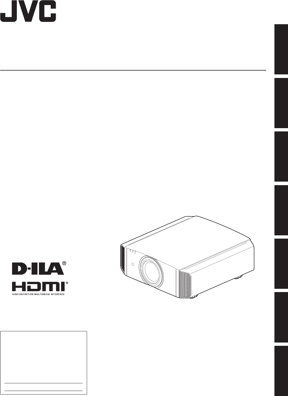
. D-ILA PROJECTOR Set up DLA-VS2500ZG DLA-VS2500G DLA-VS2300ZG DLA-VS2300G Getting Started INSTRUCTIONS Operate Adjust/Set Maintenance . Troubleshooting . Others For Customer use : Enter below the serial No. which is located on the back of the cabinet. Retain this information for future reference. Model No. DLA-VS2500ZG DLA-VS2500G DLA-VS2300ZG DLA-VS2300G Serial No.
Safety Precautions Getting Started IMPORTANT INFORMATION WARNING: WARNING TO PREVENT FIRE OR SHOCK HAZARDS, DO NOT EXPOSE THIS APPLIANCE TO RAIN OR MOISTURE. This is a Class A product. In a domestic environment this product may cause radio interference in which case the user may be required to take adequate measures. In case where the strong electromagnetic waves or magnetism are near the signal cable, the picture will contain noise.
IMPORTANT SAFEGUARDS - All the safety and operating instructions should be read before the product is operated. - The safety and operating instructions should be retained for future reference. - All warnings on the product and in the operating instructions should be adhered to. - All operating instructions should be followed. - Place the projector near a wall outlet where the plug can be easily unplugged. - Unplug this product from the wall outlet before cleaning.
. Getting Started - Do not place combustibles behind the cooling fan. For example, cloth, paper, matches, aerosol cans or gas lighters that present special hazards when over heated. - Do not ceiling-mount the projector to a place which tends to vibrate; otherwise, the attaching fixture of the projector could be broken by the vibration, possibly causing it to fall or overturn, which could lead to personal injury. - Use only the accessory cord designed for this product to prevent shock.
CAUTION: Location information of the labels Getting Started Use of controls or adjustments or performance of procedures other than those specified herein may result in hazardous radiation exposure. This Projector is classified as a CLASS 2 LASER PRODUCT. DO NOT STARE INTO BEAM . This CLASS 2 LASER PRODUCT label and Caution label are located on the TOP Side surface of the projector. Light source specifications 30 W Laser diodes ×2 Wavelength 450-460 nm Maximum output is 64.
POWER CONNECTION Getting Started For USA and Canada only Use only the following power cord. Power cord The power supply voltage rating of this product is AC110V – AC240V. Use only the power cord designated by our dealer to ensure Safety and EMC. Ensure that the power cable used for the projector is the correct type for the AC outlet in your country. Consult your product dealer.
ENGLISH Getting Started Information on Disposal of Old Electrical and Electronic Equipment and Batteries (applicable for countries that have adopted separate waste collection systems) Products and batteries with the symbol (crossed-out wheeled bin) cannot be disposed as household waste. Old electrical and electronic equipment and batteries should be recycled at a facility capable of handling these items and their waste byproducts.
ESPAÑOL / CASTELLANO Getting Started Información acerca de la eliminación de equipos eléctricos, electrónicos y baterías al final de la vida útil (aplicable a los países de la que hayan adoptado sistemas independientes de recogida de residuos) Los productos y las baterías con el símbolo (contenedor con ruedas tachado) no podrán ser desechados como residuos domésticos.
Contents Safety Precautions .................................................. 2 Accessories/Optional Accessories ........................ 10 Check the Accessories ...................................... 10 Optional Accessories ......................................... 10 Controls and Features ........................................... 11 Main Unit - Front ................................................ 11 Main Unit - Bottom ............................................. 11 Main Unit - Rear ................
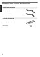
Accessories/Optional Accessories . Power cord (for USA) (about. 2 m) ......................................... 1 piece . Power cord (for EU) (about. 2 m) ............................................ 1 piece Optional Accessories 0 Remote control: Model no. RM-MH13G 0 AAA-size battery . .
Controls and Features Getting Started Main Unit - Front D E . E C AB A Lens P D Indicator This is a projection lens. Do not look through the lens while an image is projected. 0 For O, the lens is sold separately. B Lens sheet P The lens comes attached with a protective sheet when you purchase this product. Refer to “Indicator Display on the Main Unit”p. 52. E Exhaust vent Warm air is discharged to cool down the internal temperature. Do not block the vents.
Getting Started Main Unit - Rear F F . H K J I H Input terminals For details on the terminals. refer to “Main Unit - Input Terminals”p. 13. I Operation panel For more details, please refer to the “Operation panel” in the diagram below. J Remote Sensor (rear) Please aim the remote control (sold separately) at this area when using it. * There is also a remote sensor at the front. K Power input terminal Connect the supplied power cord to this terminal.
Getting Started Main Unit - Input Terminals Enlarged View of Rear Face A B C D . E A [HDMI 1] input terminal B [HDMI 2] input terminal For connecting to devices that support HDMI output. (p. 19) It is fitted to the M3 lock hole. The depth of the screw hole is 3 mm. C [LAN] terminal (RJ-45) The projector can be controlled by connecting it to a PC through the computer network for control commands to be sent to the projector.
Getting Started Remote control (sold separately, model no. RM-MH13G) A B [STAND BY] J [C.M.D.] For setting frame interpolation. (p. 29) Turns off the power. (p. 23) B C [ON] C [INPUT] Select an input from [HDMI 1], [HDMI 2], and [Dual]. (p. 22) * The Dual function is available only on 2. C D E F G K [LIGHT] Turns on the power. (p. 22) A B D [LENS CONTROL] J P Confirms a selected item. M [BACK] N [PICTURE MODE] E [HIDE] Hides the image temporarily. (p.
. Getting Started Loading Batteries into the Remote Control (Sold Separately) 0 If the remote control has to be brought closer to the projector to operate, it means that the batteries are wearing out. Replace the batteries with new ones (AAA). 0 Insert the batteries according to the t s marks. Be sure to insert the s end first. 0 If an error occurs while using the remote control, remove the batteries and wait for five minutes. Load the batteries again and operate the remote control.
Installing the Projector Precautions during Installation Do not install at the following locations Maintain clearance from the wall, etc. Installing the screen Install the unit and the screen such that they are perpendicular to each other. Screen Front Please choose a screen material with non-uniform patterns. Uniform patterns such as checks may cause interference patterns to occur. In this case, you can change the size of the screen to make the interference patterns less noticeable.
Precautions during Mounting Securing (mounting) the projector . 0 0 Be sure to ask your dealer to install the unit for you. Installing the unit on your own may cause the unit to fall resulting in injury. 0 Take the necessary actions to prevent the main unit from falling off such as during an earthquake. 0 Regardless of the warranty period, JVC is not liable for any product damage caused by mounting the unit with non-JVC ceiling fittings or to an environment that is not suited for ceiling mount.
Adjusting the Position Adjusting the elevation angle of the projector The height and inclination of the unit (0 to 5 mm) can be adjusted by turning the foot. Lift the unit and adjust the foot (x4). Adjusting the position of the image By using the lens shift feature of this unit, you can shift the image upward/downward or to the left/right. Set it to your preferred position.
Connecting the Projector 0 Do not turn on the power until connection is complete. 0 The connection procedures differ according to the device used. For details, please refer to the instruction manual of the device to be connected. 0 This projector is used for projecting images. To output the audio of connected devices, please connect a separate audio output device, such as an amplifier or speaker. 0 The images may not be displayed depending on the devices and cables to be connected.
Connecting to the LAN Terminal Hub This Unit To [LAN] Terminal Network Connection Cable (Sold Separately) Set up Server . Desktop PC, etc. The network is used to control this unit. It is not used for sending or receiving video signals. 0 0 Please contact your network administrator for information concerning the network connection. 0 For more information on control, please refer to “External Control” (p. 45). Connecting to the RS-232C Terminal This Unit Laptop, etc.
Connecting the Power Cord (Supplied Accessory) A Connect the power cord supplied to the power input terminal on the main unit B Insert the supplied power plug into the wall outlet. Set up A Power Cord (Supplied) B Precautions to prevent fire and electric shock 0 The power consumption of this unit is large. Please connect it directly to the wall outlet. 0 Pull out the power plug when the unit is not to be used for a prolonged period of time. 0 Connect it using only the power cord supplied.
Viewing Videos STANDBY/ON LIGHT MEMO WARNING 0 When you are using this unit, be sure to remove the lens sheet. P 0 Connect the power cord, and ensure that the “STANDBY/ON” indicator lights up in red. 1 Turn on the power Projector unit: press the A [STANDBY/ON] button Remote control (sold separately): press the C [ON] button 0 3 1 The “STANDBY/ON” indicator light switches from red to green (light goes off after the unit starts up).
3 Turn off the power Projector unit: press the A [STANDBY/ON] button Remote control (sold separately): press the B [STAND BY] button 0 While the “Are you sure you want to turn off?” message is displayed, press the button again. 0 The laser light source turns off, and the “STANDBY/ON” indicator switches from a green light to a red blinking light. 0 After the light goes off, the fan will run for about 5 seconds to cool down the laser light source (Cool-down mode).
Adjustments and Settings in the Menu Pressing the [MENU] button displays the menu. Press the [JKH I] keys to select an item, followed by pressing the [OK] button to confirm the selection. List of Menu Items Picture Adjust IPicture Mode .................................................................................................................................................... p. 26 9 Sharpness ...........................................................................................................
Display Setup IBack Color ........................................................................................................................................................ p. 37 Position ................................................................................................................................................... p. 37 ISignal Display ...................................................................................................................................................
Picture Adjust Picture Mode You can adjust the image quality according to the type of video image you are viewing. Item Description Natural Image quality that focuses on natural color and gradation reproduction. Suitable for displaying video images in general. Dynamic This is the picture setting best suited for viewing the picture in a room that cannot be made completely dark. User 1 to User 6 Enables user-defined image quality data to be saved and retrieved.
Color Management Each of the colors is adjustable according to the user’s preference. 1 Select the “Picture Adjust” " “Color Management” menu, and press the [OK] button. 2 Set “Color Management” to “On”, and adjust to the preferred color. A Select “Color Selection”, and press the H I keys to select the color to adjust 0 For color adjustment, select the color from the following: “Red”, “Orange”, “Yellow”, “Green”, “Cyan”, “Blue”, “Magenta”.
Color Temp. For setting the color temperature of the video image. Preset Setting Description 5500K, 6500K, 9500K Increasing the value enhances the blue tone of the video image, while decreasing the value enhances the red tone. High Bright Color temperature that gives priority to brightness. Custom 1 to Custom 3 The color temperature of video images can be adjusted manually and saved as one of the three customized settings.
Clear Motion Drive For reducing the after-image, which occurs in a fast-moving scene. 0 Pressing the [C.M.D.] button each time switches the mode in the following sequence: “Off”"“Mode1”"“Mode2”"“Mode3”"“Mode4”"“Off”... Setting Description Off No black insertion and no motion interpolation. Mode1 Black insertion weak. Mode2 Black insertion strong. Mode3 Motion interpolation weak. Mode4 Motion interpolation strong. * C.M.D. is the abbreviation for Clear Motion Drive.
Input Signal Input Level For setting the dynamic range (gradation) of the video input. 0 If the dynamic range is not appropriate, the bright areas become overexposed, and the dark areas become underexposed. Setting Description 0-255 (PC) Select this setting if you are inputting PC signals (dynamic range: 0 - 255). 16-235 (Video) Select this setting if you are inputting video signals (dynamic range: 16 - 235). Color Space For setting the color space of the input signal.
Mask For hiding the peripheral area of the image with a mask (black strip). Off Setting Description Off Not masked. 2.5% Masks about 2.5% of the peripheral area of the image. 5% Masks about 5.0% of the peripheral area of the image. Custom Masks about 0% to 5% of the four sides of the image. On Mask: black strip around the periphery Picture Position (Horiz./Vert.
Installation Lens Control P Focus / Zoom / Shift For adjusting the lens according to the projection position A Press the [LENS CONTROL] button, and use the [JKH I] keys to adjust Focus, Zoom (screen size), and Shift (screen position) . Focus 0 Pressing the [LENS CONTROL] or [OK] button each time switches the mode in the following sequence: “Focus”"“Zoom”"“Shift”"“Focus”... ABCD .
Pixel Adjust Adjust For setting the adjustment feature to “On” or “Off”. Adjust Area Setting Description Whole Adjusts the entire image. Zone Enables fine adjustment of each zone by dividing the screen into 11 vertical x 11 horizontal zones. Adjust Color For selecting the color to adjust (“Red” or “Blue”). Adjust Pattern Setting Description On Displays the lens adjustment pattern. Off Displays external signals, and does not display the lens adjustment pattern.
Operation procedure for Whole Adjust (Pixel) For making general adjustments to slight color fringing in the horizontal/vertical directions of the video image. A Set “Adjust Area” to “Whole” B Select “Adjust Color” and “Adjust Pattern Color” C Select “Adjust(Pixel)”, and press the [OK] button 0 The selected adjustment pattern and Adjustment (Pixel) window are displayed. Adjustment (Pixel) Window V (Vertical) Adjustment Pattern Pixel Adjust Red Whole Adjust (Pixel) H 0 V 0 Color A. ADJUST. Color P. A.
Operation procedure for Whole Adjust (Fine) For making general adjustments on the misalignment of the entire screen using “Adjust(Pixel)”, followed by making fine adjustments. A Set “Adjust Area” to “Whole” B Select “Adjust Color” and “Adjust Pattern Color” C Select Adjust(Fine), and press the [OK] button 0 The selected adjustment pattern and Fine window are displayed. 0 The adjustable range may be smaller depending on the pixels being adjusted on the entire screen.
Operation procedure for Zone Adjust For fine-tuning misalignments on a part of the screen after adjusting the overall screen misalignment using “Adjust(Pixel)” and “Adjust(Fine)”. 0 The screen can be divided vertically and horizontally into 10 sections for partial adjustments to be made. A Set “Adjust Area” to “Zone” B Select “Adjust Color” and “Adjust Pattern Color” C Select Adjust(Fine), and press the [OK] button 0 The selected adjustment pattern and Zone Adjustment window are displayed.
Installation Style For setting to “Front”, “Ceiling Mount (F)”, “Rear”, or “Ceiling Mount (R)” according to the installation status of the projector. 0 “Front” or “Ceiling Mount (F)” is set when projector is installed in the front with respect to the screen. 0 “Rear” or “Ceiling Mount (R)” is set when projector is installed in the rear with respect to the screen. LED Indication When LED Indication is set to “Off”, the LED indicator does not light up or blink under the following status.
Function Off Timer For setting the timing to power off the unit automatically (“1 Hour”, “2 Hours”, “3 Hours”, or “4 Hours”) when it is not operated for a period of time. Network Setting DHCP Client Description On Obtains the IP address automatically from the DHCP server inside the connected network. Off For configuring the network settings manually. IP Address For configuring the IP address. Subnet Mask For configuring the subnet mask. Default Gateway For configuring the default gateway.
Information During video signal input Setting Description Input Displays video input terminal. Source Displays the input source. Deep Color* Displays the color bit depth of the input video signal. 0 Displayed when Deep Color information is received from the source device. Light source time Displays the laser light source time. Soft Ver. Displays the firmware version. PS Ver. Displays the version of image quality data. Unit ID Adds an ID to the projector.
Maintaining the Cabinet and Remote Control (Sold Separately) 0 Gently wipe off dirt on the cabinet with a soft cloth. 0 If it is extremely dirty, wet a cloth in water, wring dry and use it to wipe off the dirt, followed by wiping again with a dry cloth. 0 Pay attention to the following as the cabinet may deteriorate in condition or the paint may come off.
Cleaning and Replacing the Filter Clean the filter regularly Otherwise, the air intake efficiency may deteriorate, and malfunction may occur. 3 Reinstall the inner filter CAUTION 0 Make sure that you pull out the power plug from the outlet before cleaning or replacing the filter. 0 Before turning this unit upside down and placing it on the floor or a table, make sure that you lay a soft rag in advance to prevent the projector from being scratched.
Troubleshooting Before sending the unit to your authorized dealer for repair, please check the following points. The following symptoms are not malfunctions. You do not need to worry about the following symptoms if there is no abnormality on the screen. 0 A part of the top or front surface of the unit is hot. 0 A creaking sound is heard from the unit. 0 An operating sound is heard from the inside of the unit. Color smear occurs on some screens. This unit is a digital device.
Cool-down time is long Check Is the Auto Intensity function On? Action Refer to Please wait until the Cool-down mode is completed. If the p. 23 Auto Intensity function is On, it will take up to 6 minutes to process the brightness adjustment. Video image looks unnatural Colors are unnatural Check Action Refer to Is the color space of the input signal correctly set? The color may turn out unnatural when the input signal is p. 30 different from that in the projector setting.
Remote control does not work Check Action Refer to Are the batteries correctly loaded? Match the polarities (t s) correctly when loading the batteries. p. 15 Are the batteries exhausted? Replace with new batteries. p. 15 Is there an obstructing object between Remove any obstructing object. the remote control and remote sensor? p. 15 Is the remote control held too far away from the unit? p. 15 Hold the remote control closer to the sensor during use.
External Control You can control this unit by connecting it to a PC using an RS-232C null modem cable (D-sub 9-pin). The projector can be controlled by connecting it to a PC through the computer network with a LAN cable for control commands to be sent to the projector. Please use it after you have gained proper understanding from professional books or consulting the system administrator. 0 RS-232C Specifications This Unit Pin No.
Command Format The command between this unit and the computer consists of “Header”, “Unit ID”, “Command”, “Data” and “End”. 0 Header (1 byte), Unit ID (2 bytes), Command (2 bytes), Data (n bytes), End (1 byte) Header This binary code indicates the start of communication.
Remote Control Code Binary code is sent during communication. 0 The following applies to the case when the remote control code is “A”. In the case of “B”, add “36” to the beginning of the code. Remote Control Button Name Binary Code Remote Control Button Name Binary Code STAND BY 37 33 30 36 MENU 37 33 32 45 ON 37 33 30 35 BACK 37 33 30 33 HDMI 1 37 33 37 30 NATURAL 37 33 36 41 HDMI 2 37 33 37 31 DYNAMIC 37 33 36 42 Dual 37 33 34 44 USER 37 33 44 37 LENS CONTROL 37 33 33 30 C.M.D.
Communications Example This section shows the communication examples of RS-232C.
Specifications Product Name D-ILA Projector Model Name DLA-VS2500ZG, DLA-VS2500G, DLA-VS2300ZG, DLA-VS2300G Display Panel/Size D-ILA device *1, 2 0.7" (1920 x 1080 pixels) x 3 (total no. of pixels: approx. 6.22 million) Projection Lens 2.0x power zoom lens (1.4:1 to 2.8:1), motorized zoom and focusP Light source BLU-Escent Technology (Laser and Phosphor) Screen Size Approx. 60" to 200" (Aspect ratio of 16:9) P Projection Distance Refer to p. 50. P Input Compatibility Signal Refer to p. 52.
About Trademarks and Copyrights HDMI, HDMI logo and High-Definition Multimedia Interface are trademarks or registered trademarks of HDMI Licensing LCC. Screen Size and Projection Distance When a 16:9 screen is used P Screen Size Projection Distance Diagonal (inch) Width (mm) Height (mm) Wide-end (m) Tele-end (m) 60 1328 747 1.78 3.66 70 1549 872 2.09 4.28 80 1771 996 2.4 4.89 90 1992 1121 2.7 5.51 100 2214 1245 3.01 6.13 110 2435 1370 3.31 6.75 120 2656 1494 3.62 7.
When a 4:3 screen is used P Screen Size Projection Distance Diagonal (inch) Width (mm) Height (mm) Wide-end (m) Tele-end (m) 60 1219 914 2.22 4.49 70 1422 1067 2.60 5.24 80 1626 1219 2.98 6.00 90 1829 1372 3.36 6.75 100 2032 1524 3.74 7.51 110 2235 1676 4.11 8.26 120 2438 1829 4.49 9.02 130 2642 1981 4.87 9.77 140 2845 2134 5.25 10.53 150 3048 2286 5.63 11.28 160 3251 2438 6.00 12.
Types of Possible Input Signals Video (HDMI1, HDMI2) Digital Video Signal 480p/60 Hz, 576p/50 Hz, 720p/50 Hz, 720p/60 Hz, 1080p/50 Hz, 1080p/60 Hz Video (Dual) Digital Video Signal 1080p/50 Hz, 1080p/60 Hz In the Dual mode, both HDMI1 and HDMI2 need to be synchronized at 1080p/60 Hz or at 1080p/50 Hz. 0 PC Signal (HDMI1, HDMI2) No. Designation Resolution fh [kHz] Total No. of Hsize [dot] dot CLK [MHz] fv [Hz] Total No. No. of of Lines Effective [line] Dots [dot] No.
Estimated timing for laser light source replacement Displays using the solid/blinking light of the “LIGHT” indicator. The “STANDBY/ON” indicator, which shows the operating mode of the unit, is also displayed simultaneously. * “LIGHT” indicator does not light up when “LED Indication” is set to “Off” (p. 37). “LIGHT” lights up (orange) LIGHT GH WARNING . STANDBY/ON If 40,000 hours have elapsed, the brightness will be half the brightness at shipment.
Dimensions (Unit: mm) Bottom Surface 91 472 290 Top Surface 5 455 59 . Lens . Lens 337 Rear Surface Front 110 178.5 32 Ø60 110 92 . . Lens Center 24 103.5 227.5 0 Others 54 The dimensions are identical for all the models.
Index A Accessories ......................................................... Projection Screen Adjustment ............................. Adjustment and Setting by the Menu ................... Adjustment of the Image Quality .......................... Aperture ............................................................... 10 32 24 26 26 B Back Color ........................................................... 37 Basic Setting for Image Quality ............................ 26 Brightness ....................
. .