. D-ILA PROJECTOR Set up DLA-X9000 DLA-X7000 DLA-X5000 Getting Started INSTRUCTIONS Operate Adjust/Set . Maintenance Mobile User Guide http://manual3.jvckenwood.com/projector/mobile/global/ The Mobile User Guide can be viewed on mobile internet devices including smartphones and tablets. Pour utilisation par le client : Entrerci-dessous le N°de série qui est situé sous le boîtier. Garder cetteinformation comme référence pour le futur.
Safety Precautions Getting Started IMPORTANT INFORMATION This product has a High Intensity Dis-charge (HID) lamp that contains mercury. Manage in accord with disposal laws. Disposal of these materials may be regulated in your community due to environmental considerations. For disposal or recycling information, please contact your local authorities or for USA, the Electronic Industries Alliance: http://www.eiae.org. or call 1-800-252-5722(For USA) or 1-800-964-2650(For Canada).
IMPORTANT SAFEGUARDS - All the safety and operating instructions should be read before the product is operated. - The safety and operating instructions should be retained for future reference. - All warnings on the product and in the operating instructions should be adhered to. - All operating instructions should be followed. - Place the projector near a wall outlet where the plug can be easily unplugged. - Unplug this product from the wall outlet before cleaning.
Getting Started - Do not place combustibles behind the cooling fan. For example, cloth, paper, matches, aerosol cans or gas lighters that present special hazards when over heated. - Do not look into the projection lens while the illumination lamp is turned on. Exposure of your eyes to the strong light can result in impaired eyesight. - Do not look into the inside of this unit through vents (ventilation holes), etc.
POWER CONNECTION Power cord The power supply voltage rating of this product is AC100V – AC240V. Use only the power cord designated by our dealer to ensure Safety and EMC. Ensure that the power cable used for the projector is the correct type for the AC outlet in your country. Consult your product dealer. Power cord For United Kingdom For European continent countries WARNING: Do not cut off the main plug from this equipment.
ENGLISH Getting Started Information for Users on Disposal of Old Equipment and Batteries [European Union only] These symbols indicate that equipment with these symbols should not be disposed of as general household waste. If you want to dispose of the product or battery, please consider the collection systems or facilities for appropriate recycling. Battery Products Notice: The sign Pb below the symbol for batteries indicates that this battery contains lead.
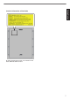
Getting Started Location information of the labels As with any bright light source, do not stare into the beam, RG2 IEC 62471-5:2015 .
Contents Getting Started Getting Started Safety Precautions .................................................. 2 Accessories/Optional Accessories .......................... 9 Check the Accessories ........................................ 9 Optional Accessories ........................................... 9 Controls and Features ........................................... 10 Main Unit - Front ................................................ 10 Main Unit - Bottom .............................................
Accessories/Optional Accessories Getting Started Check the Accessories Lens cover v ................................................................... 1 piece * It is attached to the main unit at the time of shipment. . Remote control ....................................................................... 1 piece . AAA-size batteries (for operational check) ............................ 2 pieces . Power cord (for USA) (about. 2 m) ......................................... 1 piece .
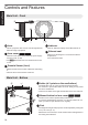
Controls and Features Getting Started Main Unit - Front D E E C . AB A Lens D Indicator This is a projection lens. Do not look through the lens while an image is projected. B Lens cover t u The lens cover opens/closes when the power supply is turned on/off. (P. 48) Refer to “Indicator Display on the Main Unit”P. 74. E Exhaust vent Warm air is discharged to cool down the internal temperature. Do not block the vents. For v, attach the lens cover when the unit is not in use.
Getting Started Main Unit - Rear F F J I . M L K I Input terminals In addition to the video input terminal, there are also other connection terminals for devices such as controllers and optional equipment. Please see “Main Unit - Input Terminals”P. 12 for more details about the terminals. J Lamp cover L Remote Sensor (rear) Please aim the remote control at this area when using it. * There is also a remote sensor at the front.
Getting Started Main Unit - Input Terminals Enlarged View of Rear Face A B C D F E . A [HDMI 1] input terminal B [HDMI 2] input terminal For connecting to devices that support HDMI output. (P. 18) It is fitted to the M3 lock hole. The depth of the screw hole is 3 mm. C [LAN] terminal (RJ-45) The projector can be controlled by connecting it to a PC through the computer network for control commands to be sent to the projector.
A B [STAND BY] Turns off the power. (P. 22) A B C [ON] B C C [INPUT] D E F G H I J Turns on the power. (P. 21) Select an input from [HDMI 1] and [HDMI 2]. (P. 21) INPUT HDMI 1 HDMI 2 INFO. MEMORY MENU MEMORY1 MEMORY2 D [INFO.] Displays the information menu. (P. 56) LENS MEMORY LENS CONTROL LENS AP. E [MEMORY MENU] C.M.D. Switches between saving, retrieving, and editing of the lens memory. (P. 24) F [MEMORY 1] K L Retrieves LENS MEMORY 1. G [MEMORY 2] M N O Retrieves LENS MEMORY 2.
Getting Started Loading Batteries into the Remote Control Loading the batteries 0 . 0 0 Removing the batteries If the remote control has to be brought closer to the projector to operate, it means that the batteries are wearing out. Replace the batteries with new ones (AAA). Insert the batteries according to the t s marks. Be sure to insert the s end first. When removing the battery, do so from the t end.
Installing the Projector Precautions during Installation Do not install at the following . Projection with the unit inclined at an angle Horizontal inclination: within ± 5 ° 0 5° 5° . Vertical inclination: within ± 15 ° . 15° 15° As the unit discharges a large amount of heat, install it with adequate clearance from the surroundings as shown below. 15° Maintain clearance from the wall, etc. .
Precautions during Mounting Securing (mounting) the projector Securing the projector (ceiling mount) Set up . . 0 When this unit is to be mounted to a fixed position for use, install it horizontally. 0 Make sure to secure the main unit to prevent accidents such as during an earthquake. 0 Be sure to ask your dealer to install the unit for you. Installing the unit on your own may cause the unit to fall resulting in injury.
Adjusting the Position Adjusting the elevation angle of the projector The height and inclination of the unit (0 to 5 mm) can be adjusted by turning the feet. Lift the unit and adjust the four feet. Adjusting the position of the image By using the lens shift feature of this unit, you can shift the image upward/downward or to the left/right. Set it to your preferred position. Æ “Adjusting the Lens According to the Projection Position” (P.
Connecting the Projector Set up 0 Do not turn on the power until connection is complete. 0 The connection procedures differ according to the device used. For details, please refer to the instruction manual of the device to be connected. 0 This projector is used for projecting images. To output the audio of connected devices, please connect a separate audio output device, such as an amplifier or speaker. 0 The images may not be displayed depending on the devices and cables to be connected.
Connecting via HDMI-DVI conversion cable Desktop PC, etc. This Unit To [HDMI 1] or [HDMI 2] input terminal Set up DVI Output Terminal HDMI-DVI Conversion Cable (Sold Separately) . 0 If noise occurs, move the desktop PC away from this unit. 0 If the video is not displayed, try to reduce the length of the cable or lower the resolution of the video transmitting equipment.
Connecting to the TRIGGER Terminal Screen This Unit Set up To [TRIGGER] Terminal Trigger Input Terminal (Ø3.5) Trigger Cable (Sold Separately) . Do not use it to supply power to other devices. 0 0 Connecting to the audio terminal of another device may cause the device to malfunction or break down. 0 Using beyond the rated value will cause the unit to malfunction. 0 The trigger terminal outputs a voltage of 12 V. Exercise adequate caution to prevent short circuit. 0 The factory setting is “Off”.
Viewing Videos STANDBY/ON LAMP MEMO WARNING 0 When you are using v, be sure to remove the lens cover. 0 Connect the power cord, and ensure that the “STANDBY/ON” indicator lights up in red. 1 Remote control: press the C [ON] button v Projector unit: press the A [STANDBY/ON] button Remote Control 3 1 MEMORY MENU HDMI 2 INFO. MEMORY1 MEMORY2 The “STANDBY/ON” indicator light switches from red to green (light goes off after the unit starts up). 0 t (u) The lens cover opens.
3 Turn off the power Remote control: press the B [STAND BY] button Projector unit: press the A [STANDBY/ON] button 0 While the “Are you sure you want to turn off?” message is displayed, press the button again. 0 The lamp turns off, and the “STANDBY/ON” indicator switches from a green light to a red blinking light. 0 After the light goes off, the fan will run for about 100 seconds to cool down the lamp (Cool-down mode). Do not disconnect the power cable while cooling is in progress.
Adjusting the Projector Screen Adjusting the Lens According to the Projection Position Press the [LENS CONTROL] button, and use the [JKH I] keys to adjust Focus, Zoom (screen size), and Shift (screen position) 1 INPUT HDMI 1 HDMI 2 INFO. MEMORY MENU MEMORY1 MEMORY2 Focus LENS MEMORY 1 LENS CONTROL LENS AP. C.M.D. . Pressing the [LENS CONTROL] or [OK] button each time switches the mode in the following sequence: “Focus” " “Zoom” " “Shift” " “Focus”...
Saving and Retrieving Adjustment Settings The Focus, Zoom, and Shift settings can be saved or retrieved, so you can switch easily to a different aspect ratio (screen size) according to the image. 0 In a state where no adjustment settings are saved (factory default), only “Lens Memory Save” is displayed. 0 Operation of the lens control feature is disabled when the lens lock is set to “On”. INPUT HDMI 1 2 MEMORY MENU HDMI 2 INFO. MEMORY1 MEMORY2 LENS MEMORY LENS CONTROL LENS AP.
Retrieving an adjustment data 1 Press the [MEMORY MENU] button to display “Lens Memory Select” 0 0 You can also retrieve an adjustment data by selecting “Installation”"“Lens Control”"“Lens Memory Select” from the menu. MEMORY1 and 2 can also be retrieved using the direct keys on the remote control. Installation >> Lens Memory Select MEMORY1 MEMORY2 --------- MEMORY MENU ------------------------Operate Exit Back BACK Select MENU .
Setting Screen Correction 1 Set Screen Adjust By selecting the optimal correction mode according to the characteristics of the screen in use, corrections can be performed to reproduce natural images with balanced colors. Installation Lens Control Keystone Front 0 Anamorphic Off High Altitude Mode Off Screen Adjust 2 Operate Exit MENU Off 3 Screen No. Select 1 Back BACK . Operate 0 This item is not available when “Color Profile” is set to “Off”.
Adjusting the Screen Size (Aspect) The screen size of the projected image can be adjusted optimally according to the original screen size (aspect) that has been input. 1 2 Press the [MENU] button to display the menu Select “Input Signal”"“Aspect” from the menu Auto Color Space Auto Aspect 16:9 Progressive Auto HDMI Signal Input . Output Image Input Image Setting 4:3 16:9 Zoom 4:3 2.
Viewing 3D Movies By using the 3D GLASSES (PK-AG1, PK-AG2, or PK-AG3) and 3D SYNCHRO EMITTER (PK-EM1 or PK-EM2), both sold separately, you can enjoy 3D video images. For 3D GLASSES and 3D SYNCHRO EMITTER that are compatible with this unit, please refer to “Optional Accessories”P. 9. 0 Installing the 3D SYNCHRO EMITTER 1 Connect 3D SYNCHRO EMITTER to the [3D SYNCHRO] terminal on the main unit Installation Example This Unit Operate 3D GLASSES PK-AG3 3D SYNCHRO EMITTER PK-EM2 .
Viewing 3D Movies 1 Connect this unit to a 3D-compatible HDMI device, and turn on the power to play back the 3D video image Format Description Auto The format is detected and configured automatically. Side by Side Select this setting if the 3D input signal is of the side-by-side format. 0 For details on how to play back 3D video images, please refer to the instruction manual of the player or recorder in use. 0 When 3D signals are received, the video image switches automatically to the 3D format.
Selecting an Image Quality According to the Video Type Setting the Picture Mode You can adjust the image quality according to the type of video image you are viewing. 1 0 INPUT HDMI 1 MEMORY MENU Press the [PICTURE MODE] button to select “Picture Mode” HDMI 2 INFO. MEMORY1 MEMORY2 You can also perform setting from “Picture Adjust”"“Picture Mode” in the menu. Item LENS MEMORY LENS CONTROL LENS AP. C.M.D. PICTURE MODE Adjust/Set 1 FILM CINEMA ANIME. NATURAL THX USER P.
Setting the Color Profile By setting the “Color Profile” (color space information) according to the “Picture Mode”, you can fine-tune the image quality according to the movie you are viewing. 1 Configure “Picture Mode” (P. 30), then select “Picture Adjust”"“Color Profile” in the menu 0 The selectable “Color Profile” settings vary according to the “Picture Mode” and also whether the signal is 2D or 3D.
List of “Color Profile” for “Picture Mode” t u Picture Mode Film 3D Signal Input Description Film 1 2D Signal Input — Color space that is close to the characteristics of Eastman Kodak Company movie films. Film 2 — Color space that is close to the characteristics of FUJIFILM Corporation movie films. — Color space suitable for digitally remastered piece of art based on a Technicolor film. Film 3 — Cinema Cinema 1 3D Film*1 Color space suitable for 3D movies recorded in film.
Adjusting to the Preferred Color (Color Management) Based on the setting of the selected “Color Profile”, you can adjust each of the following colors according to your preference: Red, Yellow, Green, Cyan, Blue, and Magenta. 1 Press the [ADVANCED MENU] button to display the “Color Profile” menu 2 Set “Color Management” to “On”, and press the [OK] button Picture Adjust > Color Profile Color Profile You can also perform setting from “Picture Adjust”"“Color Profile”"“Color Management” in the menu.
Adjusting Movies for Increased Expressiveness (Multiple Pixel Control) The new image-processing algorithm developed by JVC helps to create a natural impression that is sharper at areas in focus, and softer at areas that are not in focus, enabling you to enjoy highly expressive 4K images with a greater sense of depth. 1 Press the [MPC] button to display the adjustment menu You can also perform setting from “Picture Adjust”"“MPC Level” in the menu.
About the analysis screen Pressing the [P.ANALYZER] button on the remote control displays the analysis screen. The operation varies with the state of the OSD. * The analysis screen is not displayed during 4K 50/60p signal input. 1 Press the [P.ANALYZER] button The frequency components of the input image are displayed. . 0 The frequency components are distinguished using different colors.
Fine-tuning the Image Quality Adjusting the Output Value of the Projected Image (Gamma) You can adjust the output value of the projected image with respect to the video signal input. Example of gamma adjustment Output Value The overall image appear brighter with respect to the original image, making the dark areas more visible. A B 255 B A 0 0 255 Input Value The photos are for illustrative purposes only. .
Gamma Settings for Different “Color Profile” t u Color Profile Selectable Settings Film 1 Description Image is close to the characteristics of Eastman Kodak Company movie films. Film 2 Places more emphasis on the gradation compared to the “Film 1” setting. Custom 1 to Custom 3 Fine-tunes the gamma setting according to the user’s preference. Film 1 Places more emphasis on the contrast compared to the “Film 2” setting.
2 Adjust to the preferred setting Item Description Setting Color Selection Select “Color Selection”, and select the color to adjust White/Red/Green/Blue Picture Tone Adjusts the overall brightness automatically for a well-balanced -16 (darkens image for an result without compromising the gradation of the image. underexposed effect) to +16 (brightens image for an overexposed effect) Dark Level Adjusts the dark areas of the input image.
Procedures for adjusting the image when gamma is set to “D” If the image appears dark when gamma is set to “D”, it is recommended to adjust the image according to the following procedures. A While checking the overall image, adjust the setting value of “Picture Tone” in the + direction. B Focus on the bright area of the image and adjust the setting value of “Bright Level” in the + direction until the bright area appears appropriate.
Motion Enhance Optimal image quality with reduced image blurring is made possible by enhancing the responsiveness of the liquid crystal panel. If the image outline is unnatural, set this item to “Off”. Select “Picture Adjust”"“Blur Reduction”"“Motion Enhance” from the menu 1 Setting Description Off Does not perform correction. Low Reduces image blurring. High Further reduces image blurring than “Low”.
Adjustments and Settings in the Menu Pressing the [MENU] button displays the menu. Press the [JKH I] keys to select an item, followed by pressing the [OK] button to confirm the selection. List of Menu Items Picture Adjust Picture Mode ................................................................................................................................................... P. 30 9 Clear Black ............................................................................................................
Installation Lens Control .................................................................................................................................................... P. 23 9 Focus ......................................................................................................................................................... P. 23 9 Zoom ..........................................................................................................................................................
Picture Adjust Picture Mode You can adjust the image quality according to the type of video image you are viewing. Æ “Setting the Picture Mode” (P. 30) Clear Black Adjusts the difference in brightness in an image electrically to produce an image with contrast. Setting Description Off Does not perform correction. Low Mode with a mild effect. High Mode with a strong effect. Lamp Power The brightness of the lamp can be set to “Low” or “High”. 0 The factory setting varies with the “Picture Mode”.
Color Profile By setting the “Color Profile” (color space information) according to the “Picture Mode”, you can fine-tune the image quality according to the movie you are viewing. Æ “Setting the Color Profile” (P. 31) Color Management Each of the colors is adjustable according to the user’s preference. Æ “Adjusting to the Preferred Color (Color Management)” (P. 33) Color Temp. For setting the color temperature of the video image.
MPC Level You can enjoy natural, expressive 4K images with a stronger sense of depth. Æ “Adjusting Movies for Increased Expressiveness (Multiple Pixel Control)” (P. 34) 4K e-shift Switches the display resolution. 0 Setting values: On (4K), Off (2K) Original Resolution For selecting a resolution for the content you are viewing. 0 Setting values: Auto, 4K and 1080p * The default “Original Resolution” setting is “Auto”, which switches the resolution automatically according to the type of signal input.
Color For adjusting the color density of the video image. Setting range: -50 (lighter) to +50 (deeper) 0 * Adjustment cannot be made when “Color Profile” is set to “x.v.Color”. Tint For adjusting the hue of the video image. Setting range: -50 (reddish) to +50 (greenish) 0 * Adjustment cannot be made when “Color Profile” is set to “x.v.Color”. Input Signal Input Level For setting the dynamic range (gradation) of the video input.
Aspect The screen size of the projected image can be adjusted optimally according to the original screen size (aspect) that has been input. Æ “Adjusting the Screen Size (Aspect)” (P. 27) Progressive For setting the interpolation method for the interlaced signals. If the image outline is unnatural, set this item to “Off”.
Installation Lens Control Focus / Zoom / Shift For adjusting the lens according to the projection position Æ “Adjusting the Lens According to the Projection Position” (P. 23) Image Pattern Setting Description On Displays the lens adjustment pattern. Off Displays external signals, and does not display the lens adjustment pattern. Lock Setting On Description Locks the lens to prevent any erroneous operation on the adjustments.
Pixel Adjust Adjust For setting the adjustment feature to On (Memory 1 or Memory 2) or Off. * You can save the settings separately when an anamorphic lens is used and when you are using the projector with a screen. Adjust Area Setting Description Whole Adjusts the entire image. Zone Enables fine adjustment of each zone by dividing the screen into 11 vertical x 11 horizontal zones. Adjust Color For selecting the color to adjust (“Red” or “Blue”).
Installation Style For setting to “Front”, “Ceiling Mount (F)”, “Rear”, or “Ceiling Mount (R)” according to the installation status of the projector. 0 “Front” or “Ceiling Mount (F)” is set when projector is installed in the front with respect to the screen. 0 “Rear” or “Ceiling Mount (R)” is set when projector is installed in the rear with respect to the screen. Keystone For correcting any keystone distortion that occurs when the projector is installed at an angle with respect to the screen.
Whole Adjust (Pixel) Operation Procedure For making general adjustments to slight color fringing in the horizontal/vertical directions of the video image. A Set “Adjust Area” to “Whole” B Select “Adjust Color” and “Adjust Pattern Color” C Select “Adjust (Pixel)”, and press the [OK] button 0 The selected adjustment pattern and Adjustment (Pixel) window are displayed. Adjustment (Pixel) Window V (Vertical) Adjustment Pattern Pixel Adjust Whole Adjust (Pixel) Red H 0 V 0 Color A. GAMMA Adjust. Color P.
Whole Adjust (Fine) Operation Procedure For making general adjustments on the misalignment of the entire screen using “Adjust (Pixel)”, followed by making fine adjustments. A Set “Adjust Area” to “Whole” B Select “Adjust Color” and “Adjust Pattern Color” C Select Adjust (Fine), and press the [OK] button 0 The selected adjustment pattern and Fine window are displayed. 0 The adjustable range may be smaller depending on the pixels being adjusted on the entire screen.
Zone Adjust Operation Procedure For fine-tuning misalignments on a part of the screen after adjusting the overall screen misalignment using “Adjust (Pixel)” and “Adjust (Fine)”. 0 The screen can be divided vertically and horizontally into 10 sections for partial adjustments to be made. A Set “Adjust Area” to “Zone” B Select “Adjust Color” and “Adjust Pattern Color” C Select Adjust (Fine), and press the [OK] button 0 The selected adjustment pattern and Zone Adjustment window are displayed.
Display Setup Back Color For setting the color of the background to “Blue” or “Black” when there is no signal input. Menu Position For setting the display position of the menu. Signal Display Setting Description On Shows the input terminal for 5 seconds when input is switched. Off Not displayed. Logo Setting Description On Displays the “D-ILA” logo for 5 seconds during startup. Off Not displayed.
ECO Mode Setting Description On Enables “ECO Mode” to minimize power consumption in the Standby mode. Off 0 RS-232C / LAN communication cannot be used in the Standby mode. 0 If there is no signal transmission and operation for 20 minutes while an image is projected, the power management switches the equipment automatically into standby mode. Select this option to control via RS-232C / LAN communication in the Standby mode or if Control4 is to be used.
Remote Code For changing the remote control code. You need to configure the remote control according to the settings of this unit. On the remote control unit, press the [MENU] and [BACK] buttons at the same time for three seconds or longer to switch the code.
Replacing the Lamp The lamp is a consumable item. If the image appears dark or the lamp goes out, replace the lamp unit. When the lamp replacement time approaches, the user is notified with a message displayed on the screen and by the indicator. (P. 74) 0 Lamp Replacement Procedure CAUTION Do not insert your hands into the lamp compartment. This could cause significant deterioration in the performance of the equipment, or lead to injury and electric shock.
5 Install the new lamp unit MEMO Usable lamp life 0 When the lamp is used with “Lamp Power” set to “Low”, the lamp life on this unit is approximately 4500 hours. This is the average usable time and not a guaranteed value. 0 The lamp life may not reach 4500 hours depending on the operating conditions. 0 When the lamp has reached the end of its usable life, deterioration progresses rapidly.
Resetting the Lamp Time Reset the lamp time when you have replaced the lamp.
Cleaning and Replacing the Filter Clean the filter regularly Otherwise, the air intake efficiency may deteriorate, and malfunction may occur. 3 Reinstall the inner filter CAUTION 0 Make sure that you pull out the power plug from the outlet before cleaning or replacing the filter. 0 Before turning this unit upside down and placing it on the floor or a table, make sure that you lay a soft rag in advance to prevent the projector from being scratched.
Troubleshooting Before sending the unit to your authorized dealer for repair, please check the following points. The following symptoms are not malfunctions. You do not need to worry about the following symptoms if there is no abnormality on the screen. A part of the top or front surface of the unit is hot. A creaking sound is heard from the unit. 0 An operating sound is heard from the inside of the unit. 0 Color smear occurs on some screens. This unit is a digital device.
Video image does not appear Check Is the correct external input selected? Action Select the correct external input terminal. Refer to P. 21 Is the power of the AV device turned on? Turn on the power of the AV device and play the video. P. 18 Is the AV device properly connected? P. 18 Connect the AV device properly. Are the correct signals being output from Set the AV device properly. the AV device? P. 18 Is the cable in use an HDMI-certified cable? P. 18 Use an HDMI-certified high-speed cable.
Video image looks unnatural Colors are unnatural Check Action Refer to Is the color space of the input signal correctly set? The color may turn out unnatural when the input signal is P. 46 different from that in the projector setting. Set the “Color Space” for “Input Signal” correctly. Is the image correctly adjusted? Adjust “Color” and “Tint” accordingly. P. 46 Is the AV device properly connected? Connect the AV device properly. P.
Striped patterns appear on the screen Check Does the fabric of the screen have a regular pattern? Action Refer to Interference fringes may sometimes occur between the fabric pattern and the pixels. Please consult the authorized dealer. — Action Refer to Video images are missing Check Has screen mask been configured? Set “Mask” to “Off”. P. 47 Is the display position misaligned? Alter the “Picture Position” value so that the entire image P. 47 appears on the screen.
When the following messages appear... Message Description 0 No device is connected to the input terminal. 0 The input terminal is connected but there is no signal. No Input . Input the video signals. A video signal that cannot be used with Input video signals that can be used. this unit has been input (The names of (P. 73) input terminals such as “HDMI-1” and “HDMI-2” will be displayed in yellow). HDMI-1 . Lamp replacement Back BACK .
External Control It is possible to control this unit by connecting it to a PC using an RS-232C cross cable (D-sub 9-pin). The projector can be controlled by connecting it to a PC through the computer network with a LAN cable for control commands to be sent to the projector. Æ “ Network ” (P. 55) Please use it after you have gained proper understanding from professional books or consulting the system administrator. 0 RS-232C Specifications This Unit Pin No.
Command Format The command between this unit and the computer consists of “Header”, “Unit ID”, “Command”, “Data” and “End”. 0 Header (1 byte), Unit ID (2 bytes), Command (2 bytes), Data (n bytes), End (1 byte) Header This binary code indicates the start of communication.
Remote Control Code Binary code is sent during communication. 0 The following applies to the case when the remote control code is “A”. In the case of “B”, add “36” to the beginning of the code. Remote Control Button Name Binary Code Remote Control Button Name Binary Code STAND BY 37 33 30 36 MENU 37 33 32 45 ON 37 33 30 35 BACK 37 33 30 33 HDMI 1 37 33 37 30 FILM t u 37 33 36 39 HDMI 2 37 33 37 31 CINEMA 37 33 36 38 INFO. 37 33 37 34 ANIME. 37 33 36 36 C.M.D.
Communications Example This section shows the communication examples of RS-232C.
Specifications Product Name D-ILA Projector Model Name DLA-X9000B, DLA-X7000B, DLA-X5000B/W *1, 2 Display Panel/Size D-ILA device *3, 4 0.7" (1920 x 1080 pixels) x 3 (total no. of pixels: approx. 6.22 million) Projection Lens 2.0 x power zoom lens (1.4:1 to 2.8:1), motorized zoom and focus Light-source Lamp 265 W ultra-high pressure mercury lamp [product no.: PK-L2615U] Average lifespan: 4500 hours (“Low” mode) Screen Size Approx.
For t u, a “THX 3D Display Certification” by THX has been obtained. In addition to 2D movies, you can also enjoy faithful reproduction of images in a “quality as intended by the filmmaker” during playback of 3D movies. The THX 3D certification is “an indication of high definition and high resolution”, which is granted to products that have cleared more than 400 image quality tests. ® t u are isf-certified, so calibration can be performed by an isf-certified trainer.
When a 4:3 screen is used Screen Size Projection Distance Diagonal (Model) Width (mm) Height (mm) Wide-end (m) Tele-end (m) 60 1219 914 2.22 4.49 70 1422 1067 2.60 5.24 80 1626 1219 2.98 6.00 90 1829 1372 3.36 6.75 100 2032 1524 3.74 7.51 110 2235 1676 4.11 8.26 120 2438 1829 4.49 9.02 130 2642 1981 4.87 9.77 140 2845 2134 5.25 10.53 150 3048 2286 5.63 11.28 160 3251 2438 6.00 12.
Types of Possible Input Signals Video Digital Video Signal 480p, 576p, 720p/50 Hz, 720p/60 Hz, 1080i/50 Hz, 1080i/60 Hz, 1080p/24 Hz, 1080p/50 Hz, 1080p/60 Hz, 3840×2160/24Hz, 3840×2160/25Hz, 3840×2160/30Hz, 3840×2160/50Hz*1, 3840×2160/60Hz*1, 4096×2160/24Hz*2, 4096×2160/25Hz*2, 4096×2160/30Hz*2, 4096×2160/50Hz*1, 2, 4096×2160/60Hz*1, 2 3D Signal Frame Packing 720p/50 Hz, 720p/60 Hz, 1080p/24 Hz Side-by-side 1080i/60 Hz, 1080p/60 Hz, 1080i/50 Hz, 1080p/50 Hz, 1080p/24 Hz, 720p/50 Hz, 720p/60 Hz Top-a
Indicator Display on the Main Unit Meaning of the lighting figures STANDBY/ON The indicator lights up. LAMP WARNING The indicator appears blinking. . Operation mode display Displays using the different colors and solid/blinking light of the “STANDBY/ON” indicator.
Warning display You can tell the details of a warning from the (repeated) displays of the “WARNING” and “LAMP” indicators. The “STANDBY/ON” indicator, which shows the operating mode of the unit, is displayed simultaneously as described above. The Warning mode is activated once the message is displayed. Projection is interrupted, and the cooling fan is turned on for about 100 seconds. The power cannot be turned on again while cooling is in progress. Check the following after cooling is complete.
Dimensions (Unit: mm) Bottom Surface 91 472 290 Top Surface 5 59 455 Lens . 337 Lens . Rear Surface Front Lens Center 110 178.5 32 Ø60 24 103.5 227.5 Lamp Cover 110 92 . . 0 Others 76 The dimensions are identical for all the models.
Index A Accessories ........................................................... 9 Adjusting Distortion of the Projection Screen ....... 23 Adjustment and Setting by the Menu ................... 41 Adjustment of the Image Quality .......................... 43 ADVANCED MENU ............................................. 13 Anamorphic ......................................................... 50 Aspect ................................................................. 27 B Back Color .............................
Side by Side ........................................................ Signal Display ...................................................... Software Ver. ....................................................... Specifications ...................................................... 29 56 56 70 T THX ..................................................................... Top and Bottom ................................................... Trigger .................................................................
. Others 79
© 2015 JVCKENWOOD Corporation DLA-X9000 DLA-X7000 DLA-X5000 D-ILA PROJECTOR .