
Digital Camera User Manual


E-10
Connections & Installation
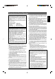
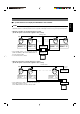
Point-to-Point Communication System
The following illustration shows a system in which a remote control unit (or a similar piece of equipment) controls a single camera.
Observe the following points when connecting components together:
• Turn all the components off before proceeding.
• Read the instruction manuals of all components before proceeding.
Control signal cable
AC 24 V
power supply
Video out
Controller
Monitor
Switch 4 : OFF
(Point to Point)
Switch 8 : ON
(Terminated 110Ω)
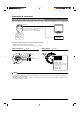
Cable connections
☞
P. 14
(Terminal side of the Ceiling Mount)
Power cable
Control signal cable
To the AC 24V power supply
To controller
Coaxial cable
To monitor
If this camera or the cables connected to this camera are used in places subject to strong electromagnetic waves or other forms
of magnetism, for example near a radio or TV transmitter, a power transformer or an electric motor, the picture may suffer from
noise and colors may be affected.
An optionally available controller is required to use a TK-C676 camera. Please contact your local dealer or installer for more
information about these controllers.
MEMO
Switch settings
☞
P. 12
(Setting switches are on the side of the Ceiling Mount)
Setting not
required
1
2
3
4
6
7
8
5
O
F
F
Setting not
required
Switch 1 : OFF
Switch 2 : OFF
Switch 4 : OFF
Switch 5 :
Configure in accordance
with the requirements of the controller
communication system.
Switch 7 : OFF
Switch 8 : ON