
Digital Camera User Manual


E-9
ENGLISH
VIDEO
SWITCHER, etc.
CONTROLLER*
Length of stub
Length of stub
CONTROL Cable
CAM1 CAM2
CAM31 CAM32
PROTOCOL(1) : ON
MACHINE ID : 01
RX TERM : ON
PROTOCOL(1) : ON
MACHINE ID : 02
RX TERM : OFF
PROTOCOL(1) : ON
MACHINE ID : 31
RX TERM : OFF
PROTOCOL(1) : ON
MACHINE ID : 32
RX TERM : ON
Length of stub
VIDEO
SWITCHER, etc.
CONTROLLER*
Length of stub
CONTROL Cable
PROTOCOL(1) : ON
MACHINE ID : 01
RX TERM : ON
PROTOCOL(1) : ON
MACHINE ID : 02
RX TERM : OFF
PROTOCOL(1) : ON
MACHINE ID : 32
RX TERM : OFF
Length of stub
CAM1 CAM2
CAM32
Terminate it
with 110 Ω.
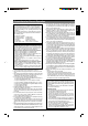
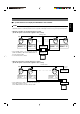
• Set the TERM switches of the cameras at each end
(CAM1 and CAM32) to ON, and the TERM switches of
the other cameras to OFF.
• Do not terminate at the controller.
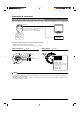
• Set the TERM switch of CAM1 to ON, and terminate at the con-
troller with a resistance of 110 Ω.
Set the TERM switches of the other cameras to OFF.
● When the controller is located at the end of a system.
(An AC 24V power source must be supplied to each camera)
● When the controller is not located at the end of a system.
(An AC 24V power source must be supplied to each camera)
Be sure to terminate the control signal cable at both ends. The cables (length of stub) connecting pieces of non-terminated
equipment (cameras or controllers) must be as short as possible. If the length of stub is too long, control precision may suffer.
MEMO
A system that does not employ the RM-P2580 as the controller