
Manual
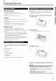


Getting Started
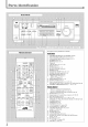
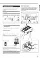
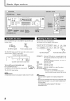
Analog connections
Audiocomponentconnections
Use the cables with RCA pin plugs (not supplied).
Connect the while plug to the audio left,jack, and the red plug to the
audio right ,jack.
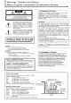
CAUTION:
If you connect a sound-enhancing device such as a graphic equalizer
between the source components and this receiver, the sound output
through this receiver may be distorted.
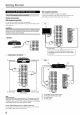
[ CDplayer 1
CD player
To audio output
TAPE
/CDR
Cassettedeckor CD recorder
Cassette deck
To audio input
To audio output
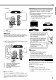
Videocomponent connections
Use the cables with RCA pin plugs (not supplied).
Comlect the white plug to the audio left jack, the red plug to the
audio right jack, and the yellow plug to the video jack.
TV
TV
To audio
output
I
_CR
IN
To video input
;onnect the TV to the MONITOFt OUT jack to view
the playback picture from the other connected video
components.
VCR
r
CO
OUT
(REC) (
TAPE
/CDR
iN I
(PLAY)
CD recorder
Note:
You can connect either a cassette deck or a CD recorder to the TAPE/
CDFt jacks. When connecting a CD recorder to the TAPE/CDR jacks,
change the source name to "CDR'; which will be shown on the display
when selected as the source. See page 9 for details.
If your audio components have a COMPU LINK jack
See also page 25 for detailed information about the connection and
the COMPU LINK remote control system.
IA, To left/right channel audio output
To left/right channel audio input
To video output
To video input
6