Instructions MICRO HD CAMERA DZ-VCA1SE LYT0468-001B
Applications Micro HD camera system can be used for following applications; (This system should only be operated by doctors or authorized persons.) (1) Operation microscope in OR neurosurgery, eye surgery, orthopedic surgery and etc. (2) Slit lamp microscope (3) Pathology microscope (4) Operation Room camera shooting operation area. (5) Endoscope operation in OR. Above applications, the system can supply HD signals to HD monitor for display and to HD VTR for recording/playback.
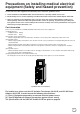
Precautions on installing medical electrical equipment (Safety and hazard prevention) For the safe use of this equipment, be absolutely sure to follow the guidelines below. 1. Leave installation of the Mobile Video Cart and the unit to a specially trained service man. 2. Be absolutely sure to use the separately sold AA-V31E isolation transformer and AC adapter AA-V112E. 3. There are openings in the equipment. Fire or electric shock may result if liquid splashes inside one of these openings.
Safety precautions Please Read Before Use WARNING: TO PREVENT FIRE OR SHOCK HAZARD, DO NOT EXPOSE THIS UNIT TO RAIN OR MOISTURE. CAUTION: This MICRO HD CAMERA should be used with a power supply of AC 120 V , 50 Hz only. To prevent electric shocks and fire hazards, DO NOT use any other power supply. WARNING: This camera head, camera control unit, camera cable and video adapter are not sterilized.
Important product safety instructions Electrical energy can perform many useful functions. But improper use can result in potential electrical shock or fire hazards. This product has been engineered and manufactured to assure your personal safety. In order not to defeat the built-in safeguards, observe the following basic rules for its installation, use and servicing. 8. Disposing of the Product Always sterilize this product before disposing of it. (See page 6.
Important product safety instructions (continued) 4. Object and Liquid Entry Never push objects of any kind into this product through openings as they may touch dangerous voltage points or short-out parts that could result in a fire or electric shock. Never spill liquid of any kind on the product. 5. Attachments Do not use attachments not recommended by the manufacturer of this product as they may cause hazards. 6. Cleaning Unplug this product from the wall outlet before cleaning.
Precautions Safety precautions ● Do not damage or modify the power cable. Doing so could result in current leakage or electric shock. ● To protect the camera and avoid electric shock hazards, always disconnect the power cord of the AC power adapter from the AC outlet when the camera is not in use for an extended period. ● Make sure that no flammable objects, water, or bits of metal get inside the unit. These could damage the unit or cause a malfunction.
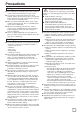
Precautions (continued) Inspection and maintenance Phenomena peculiar to CCDs (1) The product and its components must be inspected regularly by a specialist. (The product should be inspected once every three times that it is used, or once every two months.) (2) When using the product after it has not been used for at least one month, confirm that the product still operates normally and safely before attempting to actually use it. Pale, vertical streaks appear in the picture.
Contents Applications ........................................................... 2 Precautions on installing medical electrical equipment (Safety and hazard prevention) ........... 3 Safety precautions ................................................ 4 Important product safety instructions .................... 5 Precautions Safety precautions ............................................ 7 Handling precautions ........................................ 7 Inspection and maintenance.............................
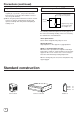
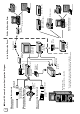
* Before using the endoscope, always be sure to sterilize the endoscope video adapter, the camera head, and the camera cable. Video cassette W-VHS SR-W7MAE W-VHS SR-W7MAE 4:3 HD monitor HV-M2000V ZIP drive (Z250S) Removable disk Inside the Operating Room Isolation transformer AA-V31E AC power adapter AA-V112 E CCU (camera control unit) DZ-VCA1SE Mobile video cart iTD GmbH VS5402.X or VS6300.
Connections ■ Connection example Notes: • Do not connect this camera to equipment other than that depicted in these connection diagrams. • Always be certain to use the AA-V31E Isolation Transformer. Endoscope application Operation field application 1/2" bayonet mount conversion adapter (GL-V62J) Endoscope Video Adapter GL-V63J* Endoscope Video Zoom Adapter GL-V64J* Lens (commercially available) Endoscope Front panel * Always use an adapter that is designed for the Endoscope.
Names of parts and their functions Camera control unit (front panel) 2 CAMERA CONTROL UNIT DZ-VCA1U GAIN SHUTTER WHITE BALANCE MODE MENU PUSH OPEN POWER CAMERA ON I OFF O 1 3 9 Interior of the function box GAIN SHUTTER NORMAL OFF AUTO MANUAL ON WHITE BALANCE SET. V.SCAN MODE MANUAL AUTO MENU BAR CAMERA PRESET TEST SG ON OFF FREEZE 3200K ALC 5600K ALC + EEI R R FINE ADJ.
Camera control unit (rear panel) SYNC OUT DC-IN HD OUT HD G Y VD B PB R PR GEN-LOCK IN C. SYNC VS /C. SYNC (75Ω) 1 2 3 1 [DC INPUT] DC input connector 4 5 6 7 5 [SYNC OUT] sync signal output jacks Input DC 12 V from the optional AA-V112U power adaptor. 2 Cover for extension slot Outputs HD (horizontal drive signal)/VD (vertical drive signal)/C. SYNC. 6 [RGB OUT] RGB signal output jacks Remove the cover to install an optional device in this slot.
Names of parts and their functions (continued) Gain control section 1 GAIN switch 2 AUTO MODE switch GAIN GAIN NORMAL AUTO ALC NORMAL MANUAL ALC + EEI AUTO ALC NORMAL OVER UNDER MANUAL ALC + EEI NORMAL OVER UNDER [AUTO] The modes set with the 2 [AUTO MODE] switch can be engaged for automatic gain adjustment. In this mode, the [GAIN UP]/[GAIN DOWN] buttons are disabled. [ALC] Adjusts the gain automatically according to changes in the brightness of the subject (auto sensitivity adjustment).
Shutter control section 1 SHUTTER switch 2 SHUTTER UP/DOWN buttons SHUTTER SHUTTER OFF ON OFF V.SCAN ON SHUTTER switch 1 and SHUTTER [UP]/[DOWN] buttons 2 V.SCAN Flicker-free mode Prevents flickering caused by fluorescent lighting in a 50-Hz area. When the shutter speed is set to 1/100 sec. (Flicker-free mode), flickering is eliminated. ●When the SHUTTER switch 1 is set to [ON] • Press the SHUTTER [UP] button 2 to decrease the shutter speed.
Names of parts and their functions (continued) White balance control section 1 WHITE BALANCE switch [AUTO] When set to this position, the camera is automatically set to a pre-adjusted white balance. Use the [SET] switch 2 to automatically readjust the white balance. WHITE BALANCE SET. MANUAL AUTO PRESET 3200K R B 5600K R FINE ADJ. B [MANUAL] Set to this position to adjust the white balance manually with the [R]/[B] volume controls 3.
Mode control section 1 SOURCE switch 2 FREEZE button MODE MODE BAR CAMERA BAR TEST SG FREEZE POSI NEGA DATE & TIME ON OFF [CAMERA] Outputs signals from the camera to the monitor. [BAR] Outputs an internal colour bar signal from the unit to the monitor. [TEST SG] Outputs an internal 100% WHITE square screen from the unit to the monitor. Use to adjust for 100% WHITE and the aspect ratio of the monitor.
Names of parts and their functions (continued) Menu control section 1 MENU switch 2 CURSOR button MENU MENU ON ON OFF [ON] The menu is displayed on the screen. Select a menu item with the CURSOR button 2. [OFF] The menu is not displayed. Menu settings will be stored in memory when this switch is set to [OFF]. When you finish menu setting, be sure to set this button to [OFF] before turning the power off. OFF • The mark (•) on the left of the menu item indicates that the item is selected.
■ MENU-PAGE 2 [IRIS ZONE] menu Change the size of the zone where automatic sensitivity compensation (ALC, ALC+EEI) is performed. Select from [LARGE], [MEDIUM], [SMALL] or [V.STRIPE] with the [LEFT]/[RIGHT] buttons. [DATE] menu Set the date. Use the [LEFT]/[RIGHT] buttons to select the part of the date to be changed (the numbers will blink). Use the [UP]/[DOWN] buttons to set the new value. [TIME] menu Set the time.
Preparation Installing a lens This unit is not provided with a lens. A special C mount type lens with flange back of 28.0 mm can be used with no adapter. To use a 1/2" bayonet mount type lens, an optional adapter (GL-V62U) is required. • Consult your lens dealer for information on installing and using your lens. • Make sure the lens is screwed all the way in. Otherwise, back focus cannot be obtained.
Before shooting Setting the switches for white balance adjustment To ensure a clear picture with correct colour tones, the back focus and white balance must be adjusted prior to shooting. Check your connections before making any adjustments. With a monitor connected, set the camera control unit's switches as shown below. WHITE BALANCE switch → “AUTO” SOURCE switch → “CAMERA” SHUTTER switch → “OFF” GAIN SHUTTER OFF NORMAL AUTO MANUAL WHITE BALANCE ON SET. V.
Basic operation While referring to the monitor, shoot a white subject (such as a wall or sheet of paper) in full screen under the same lighting conditions as those that will exist during the actual shoot. White balance adjustment 1 White balance adjustment (auto) SET switch WHITE BALANCE switch WHITE BALANCE SET. MANUAL AUTO PRESET 3200K R B 5600K Set the WHITE BALANCE switch to [AUTO]. Hold the [SET] switch to the right. [AUTO WHITE] will blink in the upper left corner of the monitor screen.
Connectors 1 Input/output connector on the camera head Pin Nos. 8 19 9 18 2 10 3 11 7 1 4 16 5 12 15 13 14 Pin Nos. Signals 1 Clock output q Video signal output 2 GND w GND 3 Control signal input e Video signal output 4 Control signal input r GND 5 Sync signal input t 15 V input 6 Sync signal input y 5 V input 7 Video signal output u GND 8 GND i -8.
Micro HD camera system component list ■ HD camera system Trade name Model name Organization Camera head Camera Control Unit Handle Power code for UK Power code for EC Continent Power code for W-VHS SCSI cable Power code for ZIP drive DZ-VCA1SE Micro HD camera Option ● AC power adapter AA-V112E AC power adapter Power code for AC adapter Isolation transformer AA-V31E Isolation transformer, Plug retainer brackets, Cover plates, Torx head screws Camera cable VC-V3 Camera cable 3 m ● Camera cabl
Specifications * Design and specifications subject to change without notice. Camera head section ■ Image sensing device : ■ Shooting system : ■ Colour separation optical system : ■ Number of effective pixels : ■ Camera output : ■ Lens mount : ■ Dimensions : 1/3-inch IT-CCD (410,000 pixels) 4-CCD new dual green system 1/3 type F1.4 3-colour separation prism 768 (horizontal) x 494 (vertical), 380,000 pixels 19 pins Special mount (C mount form, flange back: 28.
Isolation transformer AA-V31E ■ Manufacturer ■ Classification ■ Input ■ Output ■ Accessories : Victor Company of Japan Limited : CLASS I : 230 V AC 1.50 A 50 Hz 2.7 A : 120 V AC 50 Hz : Plug retainer bracket x 4 Torx head screw x 8 Cover plate x 4 Flat washer x 3 Split locking washer x 3 AC power adapter AA-V112E ■ Manufacturer ■ Input ■ Output ■ Accessories ■ Classification : Victor Company of Japan Limited 50 Hz, MAX. : 120 V AC 0.8 A : 12 V DC 3.
■ Outer dimensions 78.5 72 Camera head 3 0.5 59 8.5 60 70 67.5 36 6.5 31.5 7.25 8.05 13 29 (Side) 34 (Rear) 29 (Front) (Bottom) Camera control unit 482 430 26 26 CAMERA CONTROL UNIT DZ-VCA1U GAIN (Front) SHUTTER WHITE BALANCE MODE MENU PUSH OPEN 88 POWER CAMERA ON I OFF O 289.4 SHUTTER NORMAL OFF AUTO MANUAL ON 5 WHITE BALANCE SET. V.SCAN MODE AUTO MENU BAR MANUAL CAMERA PRESET TEST SG ON OFF 55.
JVC PROFESSIONAL PRODUCTS (UK) LIMITED ULLswater House, Kendel Avenue, London W3 OXA, United Kingdom JVC PROFESSIONAL PRODUCTS GmbH Grüner Weg 10, 61169 Fiedberg/Hessen, Germany COPYRIGHT © 2000 VICTOR COMPANY OF JAPAN, LTD.