Instructions MICRO HD CAMERA DZ-VCA3U Model No. Serial No.
Contents Feature Applications .......................................................................... 3 Precautions on installing medical electrical equipment (Safety and hazard prevention) ........................................ 3 Safety precautions ............................................................... 4 Important product safety instructions ............................... 5 Precautions ........................................................................... 7 Safety precautions ........
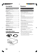
Applications Micro HD camera system can be used for following application; Endoscope operation in OR. (This system should only be operated by doctors or authorized persons.) Above application, the system can supply HD and SD signals to HD/SD monitor for display and to HD/SD VTR for recording/playback. Electrical energy can perform many useful functions. But improper use can result in potential electrical shock or fire hazards. This product has been engineered and manufactured to assure your personal safety.
Safety precautions Please Read Before Use WARNING: This MICRO HD CAMERA should be used with a power supply of AC 120 V , 60 Hz only. To prevent electric shocks and fire hazards, DO NOT use any other power supply. WARNING: This camera head with camera cable and camera control unit are not sterilized. Before using, please conduct the sterilization according to page 6. WARNING: Use the endoscope in accordance with IEC60601-1 and IEC60601-2-18. WARNING: RISK OF ELECTRIC SHOCK. DO NOT OPEN THE CABINET.
Important product safety instructions INSTALLATION AND DISPOSAL USE 1. Grounding or Polarization Precautions should be taken so that the grounding or polarization of an appliance is not defeated. 1. Accessories To avoid personal injury: • Do not place this product on an unstable cart, stand, tripod, bracket, or table. It may fall, causing serious injury to a child or adult, and serious damage to the product.
Important product safety instructions (Continued) SERVICING 1. Servicing Should the product fail to work normally, do not attempt to fix it yourself. Please rely on a qualified service person. Note: Before returning the camera head, endoscope adapter, be sure to sterilize the camera head with cable and endoscope. 2. Damage Requiring Service Unplug this product from the wall outlet and refer servicing to qualified service personnel under the following conditions: a.
Precautions Safety precautions L Do not damage or modify the power cable. Doing so could result in current leakage or electric shock. L To protect the camera and avoid electric shock hazards, always disconnect the power cord of the camera control unit from the AC outlet when the camera is not in use for an extended period. L Make sure that no flammable objects, water, or bits of metal get inside the unit. These could damage the unit or cause a malfunction.
Precautions (Continued) Inspection and maintenance Phenomena peculiar to CCDs The product and its components must be inspected regularly by a specialist. (The product should be inspected Pale, vertical streaks appear in the picture. once a year). Monitor screen Camera Head Section High-intensity subject (electric light, lamp, the sunlight, etc.) 1. Leave installation of the product to a specially trained service personnel. 2.
Connections L Connection example DT-V1900CG (Optional) Endoscope adapter (Optional) Endoscope (Commercially available) MUTING DEGAUSS UNDER SCAN PULSE CROSS COLOR OFF MENU SCREENS CHECK ASPECT AREA MARKER SLOT 1 A VOLUME SLOT 2 B C POWER SLOT 3 E D Camera head F INPUT SELECT SR-W7MAU (Optional) (W-VHS) Connector Cap Video S(Y/C) Out HD (Y, PB, PR) Out GENLOCK IN/OUT NTSC OUT SXGA OUT Front HD OUT ~AC IN DV GBR Y Connector PB CAMERA Y/C (S) PR VBS To each equipment Iso
Name of parts and their functions Camera control unit (front panel) 5 OUTPUT LEVEL 2 AUTO WHITE BALANCE AUTO MANUAL CAMERA MANUAL MENU SETTING ON POWER OFF SETTING ADJUST GAIN SHUTTER 3 1 [POWER] power switch and power indication LED When switching power on again after it is just switched off: Wait for more than 5 seconds before switching it on.
Camera control unit (rear panel) 1 GENLOCK IN/OUT NTSC OUT SXGA OUT HD OUT ~AC IN DV Y GBR PB Y/C (S) PR VBS 2 3 4 1 [AC INPUT] power input connector To input AC120V. 2 Equal-potential connector 3 Cover for extension slot Remove the cover to install an optional device in this slot. 5 6 7 5 [GENLOCK IN/OUT] sync signal input/output Input/output of composite sync signal for external sync. (menu-based switching). 6 [SXGA OUT] SXGA output section Output of progressive scan GBR signal.
Names of parts and their functions (continued) Output level control section OUTPUT LEVEL 1 AUTO MANUAL OUTPUT LEVEL AUTO MANUAL CAMERA WHITE BALANCE AUTO MANUAL MENU SETTING ON POWER OFF SETTING ADJUST 2 GAIN SHUTTER ADJUST GAIN 3 RED ON I OFF O BLUE ENHANCE FREEZE BAR 4 4 SHUTTER UP/SHUTTER DOWN button 1 GAIN switch [AUTO] Adjusts gain automatically. In this mode, the [GAIN UP]/[GAIN DOWN] button 3 and [SHUTTER UP]/[SHUTTER DOWN] button 4 operations are disabled.
White balance control section WHITE BALANCE 5 AUTO OUTPUT LEVEL WHITE BALANCE MANUAL MENU SETTING SETTING AUTO MANUAL CAMERA AUTO MANUAL ON POWER OFF 6 SETTING ADJUST GAIN SHUTTER RED ON I OFF O BLUE ENHANCE FREEZE BAR RED BLUE 7 5 WHITE BALANCE switch 6 SETTING button 7 R/B button [AUTO] When set to this position, the camera is automatically set to a pre-adjusted white balance. To automatically readjust the while balance, use [SETTING] button 6 .
Names of parts and their functions (continued) Mode control section OUTPUT LEVEL AUTO MANUAL CAMERA WHITE BALANCE AUTO MANUAL MENU SETTING ON ENHANCE FREEZE BAR 8 9 10 POWER OFF SETTING ADJUST GAIN RED SHUTTER ON I OFF O BLUE ENHANCE FREEZE BAR 8 ENHANCE button To set enhance. 10 BAR button By pressing this button, LED will light up, and the enhance will be functional.
L MENU [INDICATION1] menu Set the display on the top left of HD OUT and SXGA OUT screen. . I ND I ND I ND I D / DA T S YN I I I C E C CA CA CA OD &T T T T E I I ON 1 I ON2 I ON3 ME I D / COD E GA I N& S HU T OF F Selection items and functions are as follows: Selection items Functions ID/CODE Displays the content set under ID/CODE menu. GAIN&SHUT OFF Displays the gain value and shutter value. No display [INDICATION2] menu Set the display on the top right of HD OUT and SXGA OUT screen.
Names of parts and their functions (continued) [ID/CODE] menu Edit ID/CODE that can be displayed on the screen. • Select from INDICATION 1, 3 menu to see if it can be displayed. • Message is up to 24 alphanumeric characters. • Characters that can be used: A-Z, 0-9, ., :, -, /, and space. [DATE&TIME] menu To change date and time setting, and date display format.
Basic operation White balance adjustment a AUTO While watching the monitor, shoot a white object with full screen under the same lighting condition as actual shooting. SETTING button Set the WHITE BALANCE switch to [AUTO]. When you press and hold [SETTING] button, [AUTO WHITE] WHITE BALANCE WHITE BALANCE AUTO switch MANUAL will blink at the upper left corner of the screen. When white balance adjustment is complete, the indication changes to [AUTO WHITE OK].
Basic operation (Continued) Operation of Micro HD camera Connector Cap Mark (Red) Check system operation according to the following procedures. Connector 1. Insert the camera connector while aligning it to the red Camera head mark as shown on the left figure. When cap is connected to the camera connector: Turn the cap counterclockwise to remove it. 2. Connect the endoscope adapter to the C mount of camera CAMERA head. 3.
Connector a Camera cable connector input/output terminals (CCU side) 1. Sync signal output 2. Sync signal output 3. Shutter speed control signal 12 11 10 2 13 3 14 15 4. Shutter speed control signal 5. Shutter speed control signal 1 16 19 8 7 4 17 18 9 5 6 6. Control signal input 7. DC 15V output 8. DC 5V output 9. GND 10.–7.5V output 11.B signal input 12.GND 13.G signal input 14.GND 15.R signal input 16.GND 17.Basic clock input 18.GND 19.
Specifications Design and specifications subject to change without notice. MICRO HD CAMERA DZ-VCA3U Camera head section L Image sensing device L Shooting system : 1/3-inch PS-CCD (350,000 pixels) : 3-CCD system L Color separation optical system L Number of effective pixels : 1/3-inch F1.4 3-color separation prism : 659 (horizontal) x 494 (vertical), 330,000 pixels approximately L Camera output L Lens mount : 19 pins : Standard C mount ( flange back: 17.
L Outer dimensions Camera head (Top) 57.2 43 1.5 12.7 51.4 27.4 44 57.
Optional Equipments Isolation transformer AA-V31U L Input : 120 V AC 3.1 A 60 Hz L Output L Weight : 120 V AC 3.0 A 60 Hz : 6.7kg L Accessories : Plug retainer bracket x 3 Torx head screw x 8 Cover plate x 3 Flat washer x 3 Split locking washer x 3 HD monitor DT-V1900CG L Power requirements : 120 V AC 60 Hz L Power consumption L Dimensions : 1.6 A : 476 mm (W) x 407.5 mm (H) x L Weight 529 mm (D) : 31.
Warranty and after-sales-service Warranty record confirmation and safekeeping This product is sold with a warranty card attached. Warranty card has been delivered to sales dealer of this product. Please check your particulars and the record after filling, and keep it properly. L Warranty period: Warranty period is one year from the date of purchase. Thereafter, service will be chargeable. Servicing will be done by sales dealer based on record written in warranty card.
DZ-VCA3U VICTOR COMPANY OF JAPAN, LIMITED COPYRIGHT 2002 VICTOR COMPANY OF JAPAN, LTD.