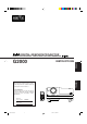
DIGITAL GRAPHICS PROJECTOR MANUEL D’INSTRUCTIONS : PROJECTEUR GRAPHIQUE NUMÉRIQUE INSTRUCTIONS FRANÇAIS ENGLISH G2000 For customer Use: Enter below the Serial No. which is located on the side panel of the cabinet. Retain this information for future reference. Pour l’utilisateur: Inscrivez ci-dessous le No de série situé sur le panneau latéral du coffret de l’appareil. Conservez cette information à titre d’information. OPERATE COMPUTER VIDEO T VOL.
G2000 Cover(A4) 4 99.11.
INSTRUCTIONS DIGITAL GRAPHICS PROJECTOR ENGLISH G2000 1 G2000 SubcoverEN 1 99.11.
Thank you for purchasing this projector. Before using it, read and follow all instructions carefully to take full advantage of the projector's capabilities. SAFETY PRECAUTIONS IMPORTANT INFORMATION WARNING : TO PREVENT FIRE OR SHOCK HAZARDS, DO NOT EXPOSE THIS APPLIANCE TO RAIN OR MOISTURE. CAUTION : To reduce the risk of electric shock, do not remove cover. Refer servicing to qualified service personnel. This projector is equipped with a 3-blade grounding-type plug to satisfy FCC rule.
– This product should be operated only with the type of power source indicated on the label. If you are not sure of the type of power supply to your home, consult your product dealer or local power company. – The product should be placed more than one foot away from heat sources such as radiators, heat registers, stoves, and other products (including amplifiers) that produce heat. – This product is equipped with a three-wire plug. This plug will fit only into a grounded power outlet.
Contents SAFETY PRECAUTIONS ........................... 2 Operating the Setting Menu ................... 32 Accessories ............................................... 5 Making Basic Settings ......................................... 32 Controls and Features .............................. 6 Front Side / Top Surface / Right Side .................... 6 Left-hand side ....................................................... 7 Bottom Surface .....................................................
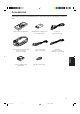
Accessories The following accessories are included with this projector. Check for them; if any item is missing, please contact your dealer. Remote control unit (RM-M100U) AV connection cable [approx. 1.5 m (4.92 ft)] Power code [approx. 2.5 m (8.2 ft)] Audio cable [approx. 3 m (9.84 ft)] (3.5 mm dia. stereo mini plug) ENGLISH Personal computer connection cable [approx. 2 m (6.
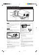
Controls and Features Front Side / Top Surface / Right Side q 1 p 9 8 7 5 4 3 2 6 6 Adjustable foot (for horizontal angle adjustment) 1 Exhaust vents Vents for cooling fans through which warm air comes out. By extending the feet, the projector angle can be adjusted up to +7°. CAUTION • Do not block the exhaust vents, or heat builds up inside, possibly causing a fire. Also, do not touch the vents, or this could cause a low-temperature burn.
Controls and Features (cont.) Left-hand side w D N TA S Y B M E P + 3 K IC U N Q LIG A G IN T T E S R E T U P O E ID V P M E T Y C N E G R E M LA M O C -2 e r w Control panel For details, refer to “Control Panel” (page 9). For details, refer to “Connector Panel” on page 11. r Adjustable foot (for horizontal angle adjustment) It is set at the shortest position when shipped from the factory. Turn the foot to make the projector level. Adjustment can be made in the range of + 1.5° and – 1.
Controls and Features (cont.) Bottom Surface t y u i t Air intake area (filter) Air is taken in through this area to cool the light-source lamp. If this area is blocked or if something that obstructs taking in or exhausting air is placed around the projector, heat may build up inside and could cause a fire. For details, refer to “Precautions for Installation” on page 15.
Controls and Features (cont.) Control Panel 1 STAND BY 2 3 LAMP 4 TEMP 5 EMERGENCY 6 VIDEO 7 COMPUTER 8 SETTING 9 4 Lamp indicator ON : After the light-source lamp has been used for more than approx. 900 hours. Blinking : Replace the lamp. Refer to “Replacing the LightSource Lamp” on page 61. 5 TEMP indicator ON: The temperature inside the projector has abnormally risen.
Controls and Features (cont.) Control Panel (Cont.) 1 STAND BY 2 3 LAMP 4 TEMP 5 EMERGENCY 6 VIDEO 7 COMPUTER 8 9 SETTING p QUICK ALIGN. button While a menu screen is shown, use this button to adjust the values for the item selected. When no menu is shown, the quick alignment function works. • When a menu is shown + 3 button: The value for the selected item increases. – 2 button: The value for the selected item decreases.
Controls and Features (cont.) Connector Panel w 2 1 Y/C VIDEO AUDIO q PC p AUDIO AUDIO R 9 G H/CS B V L Y R PB/B-Y 3 PR/R-Y 4 COMPUTER OUT REMOTE AUDIO OUT 6 5 RS-232C 7 1 Y/C (S video) input terminal (Mini DIN 4 pin) Connect this terminal to the S video output terminal of a video deck, etc. 2 VIDEO (composite video) input terminal (BNC) Connect this terminal to the composite video output terminal of a video deck, etc.
Controls and Features (cont.) Connector Panel (Cont.) w 2 1 Y/C VIDEO AUDIO q PC p AUDIO AUDIO R 9 G H/CS B V L Y R PB/B-Y 3 PR/R-Y 4 COMPUTER OUT REMOTE AUDIO OUT 6 5 RS-232C 8 7 9 COMPUTER IN (computer input) -2 terminal (BNC) These are input terminals for analog RGB signals, vertical sync (V) signals, and horizontal sync (H) signals / composite signals(Cs). Devices which have analog RGB signal output terminals can be connected.
Controls and Features (Cont.) Remote Control Unit 1 2 OPERATE e COMPUTER VIDEO 3 4 T w VOL. ZOOM 5 FOCUS W PAGE BACK q 6 MENU/ENTER 7 PRESET p 9 QUICK ALIGN. 1 Remote control’s signal transmitter 9 QUICK ALIGN. (Quick Alignment) button Use this button to select the devices connected to the projector’s COMPUTER IN (computer input) -1 and -2 input terminals.
Controls and Features (cont.) Installing Batteries Install batteries in the remote control. If the remote control has started to work erratically, replace the batteries. 1 Open the back cover. While pushing on the back cover, slide it in the direction of the arrow. 2 Install the batteries. Place the two batteries (AAA/R03-size) supplied in the remote control as illustrated below. Precautions for using batteries If batteries are used incorrectly, they may crack or leak liquid.
Installing the Projector Precautions for Installation CAUTION Do not install the projector in the following places : • There is much water, humidity or dust. • The projector may be subjected to oil smoke or cigarette smoke. • On a soft surface such as a carpet or cushion. • The projector may be subjected to direct sunlight. • Temperature is high or humidity is low.
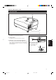
Installing the Projector (Cont.) Projection Distance and Screen Size ■ The projector’s projection lens is a zoom lens of about 1.5 x. The screen size at the maximum enlargement is 1.5 times that of the minimum size. ■ The projection distance that can be focused is 2.5 to 20 m. Install the projector within this range.
Installing the Projector (Cont.) Relationship between Projection Distances and Projection Screen Sizes ■ For 4 : 3 aspect ratio screens Projection screen size (diagonal length) Minimum projection screen size (Tele end) Maximum projection screen size (Wide end) Projection distance 8.2 ft (2.5 m) 42” (approx. 107 cm) 63” (approx. 160 cm) 9.84 ft (3.0 m) 51” (approx. 130 cm) 76” (approx. 193 cm) 13.12 ft (4.0 m) 68” (approx. 173 cm) 102” (approx. 259 cm) 16.4 ft (5.0 m) 86” (approx.
Installing the Projector (Cont.) Effective Range and Distance of the Remote Control Unit The operable distance of the remote control unit is about 10 m (32.8 ft) for direct reception. The remote control can be used by having it reflected on the screen, etc. When you use the remote control by reflecting it at the screen, the total distance of A + B should be about 10 m (32.8 ft) or less. The operable angles of the remote control unit is 50° right to left, and 15° up and down.
Connecting to Various Devices * Before connection, be sure to turn off the projector and connected devices. * Read the manual which comes with each device thoroughly. Signals that Can Be Input to the Projector The following signals can be input to the projector: ■ Video signals (1) Response to color systems Color system Input terminal NTSC NTSC4.
Connecting to Various Devices (Cont.) Connecting to Video Devices Before connection, be sure to turn off both the projector and video device. • Read the manual which comes with each video device thoroughly. • Use the supplied AV connection cable. An AV connection cable with an S video terminal is not supplied.
Connecting to Various Devices (Cont.) Connecting to Other Devices Before connection, be sure to turn off both the projector and other devices to be connected. • Read the manual thoroughly which comes with the device to be connected. • Speakers with a built-in amplifier and game devices can be connected. Use the AV connection cable and audio cable supplied, or the cable supplied with a game device. BNC-RCA conversion plug (supplied) Y/C • Game device, etc.
Connecting to Various Devices (Cont.) Connecting to Computer Devices Before connection, be sure to turn off both the projector and computer devices. • Read the manual which comes with each device thoroughly. ■ Connection to an IBM PC or IBM-compatible computer • Use the supplied computer connection cable. Also, prepare cables required for connecting the devices connected.
Connecting to Various Devices (Cont.) Connecting to Computer Devices (Cont.) Before connection, be sure to turn off both the projector and computer devices. • Read the manual which comes with each device thoroughly. ■ Connection to Macintosh • Use the supplied Personal computer connection cable and the supplied conversion adapter for Mac. • When connecting an audio output terminal such as a computer sound source to the projector, connect to the AUDIO terminal using the supplied audio cable.
Connecting to Various Devices (Cont.) Connecting the Power Cord (Supplied) After all devices have finished being connected, connect the projector’s power cord. At this time, do not turn on the MAIN POWER switch yet. 1 Insert the supplied power cord into the power input terminal (AC IN ~) of the projector. AC IN ~ 1 Power cord (supplied) 2 Insert the plug of the supplied power cord into a wall outlet.
Connecting to Various Devices (Cont.) When Turning On the Devices Connected to the Projector Turn on the switches of the projector and the devices connected in the following order. Skip over unconnected devices if there is any. Power switch of the monitor of the computer which provides input to the projector Peripheral devices of the computer which provides input to the projector (Hard disk, magneto optical disk, scanner, etc.
Basic Operations ■ Projector’s buttons The following describes the basic procedure for normal use of the projector. 1. Turning on the Power STAND BY indicator STAND BY 1 Turn on the MAIN POWER switch. OPERATE indicator ON [ ❙ ]:The main power turns on and the STAND BY indicator comes on. OPERATE button LAMP 2, 1 TEMP Projector’s indicator EMERGENCY STAND BY MAIN POWER switch VIDEO COMPUTER (ON) 1, 2 2 Press the OPERATE button for one second or more.
Basic Operations (Cont.) ■ Projector’s buttons 2. Select the video input to be projected ■ Press the VIDEO button or the COMPUTER button to switch the input. STAND BY • Each time you press either button, the selected input changes as follows.
Basic Operations (Cont.) ■ Remote control unit 4. Adjust focus ■ Adjust focus with the remote control’s FOCUS (+/–) buttons. OPERATE ■ To focus on farther points: Press the FOCUS (+) button. ■ To focus on nearer points: Press the FOCUS (–) button. COMPUTER VIDEO T VOL. ZOOM FOCUS Remote control unit FOCUS (+/–) buttons W PAGE BACK MENU/ENTER VOL. (+/–) buttons PRESET QUICK ALIGN. FOCUS AV MUTING Note • Focus adjustment can also be made on the setting menu.
Basic Operations (Cont.) ¶ For Operating Other Functions ■ Remote control unit ■ To turn off video image and audio sound temporarily OPERATE Press the AV MUTING button. ■ Press once: Video image and audio sound turn off (do not come out). ■ Press again: Video image and audio sound come out again. COMPUTER VIDEO T VOL. ZOOM Remote control unit FOCUS W MENU/ENTER PAGE BACK AV MUTING PRESET ■ To use the quick alignment function AV MUTING button AV MUTING QUICK ALIGN.
Basic Operations (Cont.) ■ Projector button ■ To display the SETTING menu The setting menu is used to make basic adjustments and settings (TRACKING, PHASE, H. POS., V. POS., FOCUS, ZOOM and AUDIO-VOL.) of the video picture being projected after installation (connection) or after inputs are switched. For operating the setting menu, refer to “Making Basic Settings” on page 32. STAND BY LAMP • Press the projector’s SETTING button. The setting menu is displayed on the screen.
Basic Operations (Cont.) ■ Remote control unit OPERATE When no menu is displayed, pressing PAGE BACK button will show the channel now being used on the upper right corner of the screen. Also, the channel can be switched to another channel. For details, refer to “Changing Channels” (page 54). COMPUTER VIDEO • When no menu is shown, press PAGE BACK button on the remote control. The channel is displayed on the upper right corner of the screen. T VOL.
Operating the Setting Menu Making Basic Settings ■ Projector’s buttons Here, we make basic video adjustment and sound volume adjustment which are set up after installation (connection). EMERGENCY Notes VIDEO COMPUTER SETTING button SETTING +3 QUICK ALIGN -2 QUICK ALIGN. buttons ■ Setting menu • This adjustment menu (setting menu) can be displayed with only the projector’s button.
Operating the Main Menu Configuration the Main Menu (AV Input) For computer inputs, see the following page. You can adjust video quality (PICTURE), audio quality (SOUND), etc. using the menus. The menus are configured as follows: Main menu (AV inputs : During AV IN input signal) PIXEL CLOCK TRACKING PHASE : Normally, no adjustment is required. The lateral size and display area of video image are adjusted. : Normally, no adjustment is required. Flickering or dim video image is adjusted. POSITION V. POS.
Operating the Main Menu (Cont.) Configuration of the Main Menu (Computer-related input) Main menu (Computer-related inputs : During COMPUTER IN-1 or -2 input signal) PIXEL CLOCK TRACKING PHASE : The lateral size and display area of video image are adjusted. : Flickering or dim video image is adjusted. POSITION V. POS. H. POS. : The vertical position of the video image being projected is adjusted. : The horizontal position of the video image being projected is adjusted.
Operating the Main Menu (Cont.) Operating the Main Menu (Basic Operation of the Main Menu) ■ Remote control unit OPERATE For projector’s menus, the setting menu and the main menu are available. Here, we explain about the operation of the main menu. For the setting menu, refer to “Making Basic Settings” on page 32. MENU/ENTER button COMPUTER VIDEO 1 Press the MENU/ENTER button. • The main menu is displayed on the screen. an item with the cursor button 2 Select 5 or ∞. T VOL.
Operating the Main Menu (Cont.) Changing the Color System ■ Remote control unit OPERATE COMPUTER VIDEO MENU/ENTER button AUTO is set for the color system when the projector is shipped from the factory. Normally, use it in AUTO. If operation in AUTO is unstable such as with color not being shown, set to a dedicated color system in accordance with the color system of the signal being input. 1 Press the MENU/ENTER button. • The main menu is shown on the screen.
Operating the Main Menu (Cont.) Changing the Language Display ■ Remote control unit OPERATE COMPUTER VIDEO MENU/ENTER button ZOOM FOCUS • The main menu is shown on the screen. • The selected item (displayed in text) is shown in magenta color on the screen. W MENU/ENTER PAGE BACK 1 Press the MENU/ENTER button. “LANGUAGE” with the cursor 2 Select button 5 or ∞. T VOL. The language in the menu display is set to English when shipped from the factory.
Operating the Main Menu (Cont.) Adjusting the Pixel Clock ■ Remote control unit OPERATE MENU/ENTER button COMPUTER VIDEO The pixel clock should be adjusted mainly for computer-related inputs. (Normally, it does not need to be adjusted for video inputs.) If a wide stripe appears on the screen, adjust the lateral size of video image and the display area (tracking adjustment) so the stripe disappears.
Operating the Main Menu (Cont.) Adjusting the Screen Position ■ Remote control unit Adjust the position of the screen if it is displaced. 1 Press the MENU/ENTER button. • The main menu appears on the screen. OPERATE COMPUTER VIDEO MENU/ENTER button • The selected item (displayed in text) is shown in magenta color on the screen. T VOL. ZOOM “POSITION” with the cursor 2 Select button 5 or ∞. FOCUS W 3 Press the MENU/ENTER button.
Operating the Main Menu (Cont.) Adjusting Picture Quality ■ Remote control unit OPERATE COMPUTER VIDEO MENU/ENTER button ZOOM FOCUS • The main menu appears on the screen. • The selected item (displayed in text) is shown in magenta color on the screen. W MENU/ENTER PAGE BACK 1 Press the MENU/ENTER button. “PICTURE” with the cursor 2 Select button 5 or ∞. T VOL. Adjust brightness, contrast, etc. so you have the desired screen.
Operating the Main Menu (Cont.) Adjusting Picture Quality (Cont.) ■Remote control unit adjustment 5 Make button 2 or 3. with the cursor ■ For video system input COMPUTER VIDEO T VOL. ZOOM FOCUS W PAGE BACK MENU/ENTER • To adjust multiple items, repeat steps 4 and 5. • To reset all items (to factory-set adjustment values “0”), select ALL RESET with the cursor buttons and press the MENU/ ENTER button.
Operating the Main Menu (Cont.) Adjusting Picture Quality (Cont.) ■Remote control unit Adjustment item Button 2 3 Gets brighter. (–30 → 0 → +30) 2 Gets lower. (–30 ← 0 ← +30) 3 Gets higher. (–30 → 0 → +30) 2 Gets less reddish. (–30 ← 0 ← +30) 3 Gets more reddish. (–30 → 0 → +30) 2 Gets less greenish. (–30 ← 0 ← +30) 3 Gets more greenish. (–30 → 0 → +30) 2 Gets less bluish. (–30 ← 0 ← +30) 3 Gets more bluish.
Operating the Main Menu (Cont.) Adjusting Sound Quality ■ Remote control unit Adjust the quality (treble/bass) of sound. 1 Press the MENU/ENTER button. • The main menu appears on the screen. OPERATE COMPUTER VIDEO MENU/ENTER button • The selected item (displayed in text) is shown in magenta color on the screen. T VOL. ZOOM the “SOUND” with the cursor 2 Select button 5 or ∞. FOCUS W 3 Press the MENU/ENTER button. MENU/ENTER PAGE BACK •The submenu items of the SOUND menu appear on the screen.
Operating the Main Menu (Cont.) Setting and Adjusting Other Functions (OPTIONS) ■ Remote control unit OPERATE COMPUTER VIDEO MENU/ENTER button The following optional functions can be set (adjusted). • MENU AUTO OFF • LINE DISPLAY • RIGHT LEFT REV. • TOP BOTTOM INV.
Operating the Main Menu (Cont.) Setting and Adjusting Other Functions (OPTIONS) (Cont.) ■Remote control unit (adjust) the desired item with the 5 Set cursor button 2 or 3. • To adjust multiple items, repeat steps 4 and 5. COMPUTER VIDEO MENU AUTO OFF T VOL. ZOOM Adjustment item Button 2/3 2/3 Sets whether to show the line display (Y/C, VIDEO, etc.) at the top of the projected screen or not. (Factory setting : ON) OFF: Does not show the line display. ON : Shows the line display.
Operating the Main Menu (Cont.) Setting and Adjusting Other Functions (OPTIONS) (Cont.) ■Remote control unit Adjustment item Button BACK COLOR OPERATE COMPUTER VIDEO 2/3 MENU/ENTER button YELLOW ZOOM COLOR TEMP. MENU/ENTER MAGENTA 2/3 2/3 Sets the vertical-to-horizontal ratio (4 : 3 or 16 : 9) of the video image projected. (Factory setting : 4 : 3) 4 : 3 : The aspect ratio of the screen becomes 4 : 3. Set it to 4 : 3 for video of NTSC, NTSC4.43, PAL, SECAM.
Operating the Main Menu (Cont.) Changing (Setting) the Source ■ Remote control unit OPERATE COMPUTER VIDEO MENU/ENTER button Normally, use the source setting in AUTO. If use in AUTO is unstable such as color not appearing, the screen being disturbed or the screen being intermitted, set to the dedicated source (forced mode) in accordance with the input signal. Also, User Source mode, which lets you set up special signals, is available.
Operating the Main Menu (Cont.) Changing (Setting) the Source (Cont.) ■ Remote control unit the MENU/ENTER button to set 5 Press (fix) it. ■ When AUTO is selected: OPERATE COMPUTER VIDEO MENU/ENTER button setting procedure, and the source display inputted appears. • Both line display and source display appear on the screen and disappear in five seconds. However, they do not appear if the line display is set to OFF. T VOL.
Operating the Main Menu (Cont.) Setting Up Channels ■ Remote control unit OPERATE COMPUTER VIDEO MENU/ENTER button T VOL. ZOOM • With multiple sources having been set on channels, when a channel is selected, incoming signal is automatically checked and switched to one of the sources registered on the channel. If a matching source is not found among the registered sources, all other available sources are searched to find a matching source. 1 Press the MENU/ENTER button.
Operating the Main Menu (Cont.) Setting Up Channels (Cont.) ■ Remote control unit the MENU/ENTER button to set 5 Press (fix). • The “LINE selection menu” is shown on the screen. OPERATE COMPUTER VIDEO LINE MENU/ENTER button Y/C VIDEO YPBPR COMP1 COMP2 NONE T VOL. ZOOM FOCUS W PAGE BACK MENU/ENTER (Line selection menu) PRESET Cursor buttons QUICK ALIGN. AV MUTING the cursor button 5 or ∞ to select 6 Press a “LINE” item.
Operating the Main Menu (Cont.) Setting Up Channels (Cont.) ■ Remote control unit OPERATE COMPUTER VIDEO ■ To set up a source, “SOURCE” : MENU/ENTER button ZOOM FOCUS • The “SOURCE SETUP” menu is displayed on the screen. • The “SOURCE” items that have been registered are shown with check marks. W PAGE BACK • The main menu appears on the screen. • If any “LINE” item is not registered, you cannot choose a “SOURCE’ or “SWNo” item. First register a “LINE” item. 2 Press the MENU/ENTER button. T VOL.
Operating the Main Menu (Cont.) Setting Up Channels (Cont.) ■ Remote control unit OPERATE COMPUTER VIDEO MENU/ENTER button ZOOM FOCUS W PAGE BACK • When the item is set, a check mark is placed next to its user name, which is registered as a “SOURCE”. • If you place the cursor on a “SOURCE” item with a check mark attached and press MENU/ENTER button, the check mark will disappear, making the item unregistered as a “SOURCE” item. ¶ To return to the main menu, press the PAGE BACK button.
Operating the Main Menu (Cont.) Setting Up Channels (Cont.) ■ Remote control unit OPERATE COMPUTER VIDEO ■ To set up a switcher number “SWNo” : MENU/ENTER button ZOOM FOCUS • The “Switcher Number Setup” menu is displayed on the screen. W PAGE BACK • The selected item is shown in magenta color on the screen. • If any “LINE” item is not selected, you cannot choose a “SOURCE” or “SWNo” item. First, register a “LINE” item. 2 Press the MENU/ENTER button (fix). T VOL.
Operating the Main Menu (Cont.) Changing Channels ■ Remote control unit OPERATE COMPUTER VIDEO MENU/ENTER button ZOOM FOCUS W PAGE BACK ■ To changing channels using a “Direct Channel” : the PAGE BACK when no menu 1 Press is displayed. • The channel number is shown on the upper part of the screen. • A channel number which has a line and source registered is displayed. (If no channel that has such registration is available, AUTO will be displayed.) T VOL.
Operating the Main Menu (Cont.) Changing Channels (Cont.) ■ Remote control unit OPERATE COMPUTER VIDEO MENU/ENTER button ZOOM 1 Press the MENU/ENTER button. • The main menu appears on the screen. the cursor button 5 or ∞ 2 Press select a submenu item, CHANNEL. to • The selected item (displayed in text) is shown in magenta color on the screen. T VOL. ■ Changing channels on the “CHANNEL Setup/ Selection” menu : FOCUS W 3 Press the MENU/ENTER button.
Operating the Main Menu (Cont.) Setting up (or Change) User Sources ■ Remote control unit A maximum of 10 types of information can be registered regarding the source being input and projected through line connection. Memo Before setting up a user source OPERATE COMPUTER VIDEO MENU/ENTER button 1 Press the MENU/ENTER button. T VOL. ZOOM FOCUS • The main menu appears on the screen.
Operating the Main Menu (Cont.) Setting up (or Change) User Sources (Cont.) ■ Remote control unit To set up (change) user names The procedure for setting up or changing user names given to user sources is described below. OPERATE COMPUTER VIDEO MENU/ENTER button 1 Press the MENU/ENTER button. • The main menu appears on the screen. the cursor button 5 or ∞ 2 Press select “USER SOURCE SETUP”. T VOL. ZOOM FOCUS W 3 Press the MENU/ENTER button.
Operating the Main Menu (Cont.) Setting up (or Change) User Sources (Cont.) ■ Remote control unit 6 Press the MENU/ENTER button. • The “USER NAME” setup menu appears. OPERATE COMPUTER VIDEO MENU/ENTER button T VOL. If a user name is not registered to the selected number (“No”), the source area of the selected line is registered as a user source, and a temporary user name is displayed on the “USER NAME” item on the screen.
Operating the Main Menu (Cont.) Setting up or Changing the Display Size ■ Remote control unit OPERATE COMPUTER VIDEO MENU/ENTER button The image display size (the numbers of horizontal /vertical effective dots and horizontal /vertical display positions) of the input signals (sources) registered in the user source setup can be adjusted. 1 Press the MENU/ENTER button. • The main menu appears on the screen. the cursor button 5 or ∞ to select 2 Press “DISPLAY SIZE”. T VOL.
Replacing the Fuse A fuse is used to protect the power source of the projector. If the fuse is burned out, replace it. When the power switch is turned on but no power is supplied to the projector, check the fuse. When replacing the fuse, obtain the same type of fuse rated 15A/250V. If there are any unclear points, contact the dealer where you purchased your projector. off the main power switch and 1 Turn disconnect the power cord from both the projector and the wall outlet. ‡] position.
Replacing the Light-Source Lamp The light-source lamp has its service life. It is approximately 1000 hours. When the light-source lamp approaches the end of its service life, its degradation progresses rapidly. When the lamp’s used hours exceed 900 hours, the projector’s LAMP indicator comes on. Also, at the start of projection (lamp energized), the message “REPL.-LAMP” appears on the projection screen for about two minutes. Then, replace with a new light-source lamp, or arrange for a replacement lamp.
Replacing the Light-Source Lamp (Cont.) the lamp-unit screws, raise 2 Loosen the handle, and pull out the lamp unit. Screw Loosen the two screws with a flat-end screwdriver. Note • The screws are fitted so that they do not come off the lampunit. Lamp unit 2 1 the new lamp unit fully 3 Insert inside and fasten the screws. Handle Lamp unit Fasten the two screws with a flat-end screwdriver.
Replacing the Light-source Lamp (Cont.) Resetting the Lamp Use Time After replacing with a new light-source lamp, reset the counter inside the projector. This works to reset the life calculation of the light-source lamp, allowing the used time of the new light-source lamp to be accumulated. on the MAIN POWER switch 1 Turn to go into stand-by mode. ■Projector’s button • ON [ ❙ ]:The main power turns ON and the STAND BY [MAIN POWER switch] indicator lights.
Cleaning and Replacing the Filter Clean the filter periodically. If the filter is heavily stained and does not get clean, or if it is damaged, replace the filter with a new filter (part No.: LC30208). Otherwise, dirt may get inside and appear on the screen, possibly preventing you from enjoying the video image fully. If dirt gets inside or if you need information about the filter, consult a authorized dealer where you have purchased the projector or Service center. 1 Turn off the MAIN POWER switch.
Troubleshooting Solutions to common problems related to your projector are described here. If none of the solutions presented here solves the problem, unplug the projector and consult a authorized dealer or service center. • Is the main power switch turned on? Corrective action • Insert the power cord (plug) firmly. Page 24 • Turn on the MAIN POWER switch. 26 • Turn off the main power switch, and • Is fuse burned out? check the fuse. If it is burned out, replace it.
Symptom Video image is abnormally dark or bright. Probable cause • Is picture quality (color density, etc.) adjusted correctly? • Is the correct CLAMP selected? Color is poor or unstable. • Is picture quality (color density, etc.) adjusted correctly? • Is the correct broadcast system (color system) selected? • Are signals (scanning frequency, etc.) to connected devices appropriate? Corrective action • Adjust picture quality on the menu. Page • Select the correct CLAMP on the OPTION MENU.
Specifications Optical mechanism system • Projection method • D-ILA device 3D-ILA device, 1 lens, 3 primary color optical shutter method 0.9" (2.3cm) measured diagonally (1365 pixels ×1024 pixels) × 3 (Total number of pixels : 4,193,280) Electric-driven zoom of 1.5 × Approx.42" (107cm) to Approx.300" (762cm) [recommended] to Approx.
Specifications (Cont.) Horizontal sync/composite sync signal (H/Cs) H : 1V(p-p) to 5V(p-p), high impedance (positive/negative polarity) Cs : 1V(p-p) to 5V(p-p), high impedance (positive/negative polarity) Vertical sync signal (V) V : 1V(p-p) to 5V(p-p), high impedance (positive/negative polarity) * Some connected devices may not correspond to composite sync (Cs) or G on sync signal. • AUDIO (For COMPUTER IN-2) 1-line, stereo mini-jack × 1 0.
Specifications (Cont.) Outside dimensions ■ Top Unit: Inch (mm) 20 (505)*1 14-1/2 (367) 15-3/8 (388) *1: Protrusion excluded φ4-1/8 (φ102) 5-1/4 (133)*1 ■ Front ■ Side 15-5/8 (388) ENGLISH 15-1/2 (392) 10-1/2 (264) 8-1/8 (204) 10- /2 (264) 1 2-1/8 (53) 8-3/8 (211) 20 (505)*1 10-1/8 (256) 2-5/8 (68) 5 2- /8 (64) DTV-format signals * The following are DTV-format signals that can be input.
Specifications (Cont.
G2000 Cover(A4) 1 99.11.
G2000 DIGITAL GRAPHICS PROJECTOR Confidential and proprietary information. © Copyright 1999 by Hughes-JVC Technology Corporation. All worldwide rights reserved. This manual was produced by Hughes-JVC Technology Corporation and may be revised without prior notice. No part of this manual may be reproduced in any form without the express written permission of Hughes-JVC Technology Corporation.