PLASMA DISPLAY MONITOR GD-V501PCE INSTRUCTIONS
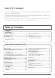
Dear JVC Customer Welcome to the JVC family of customers. We hope that you will have many years of enjoyment from your new Plasma Display. To obtain maximum benefit from your set, please read these Instructions before making any adjustments, and retain them for future reference. Retain your purchase receipt also, and note down the model number and serial number of your set in the space provided on the rear cover of these instructions. Table of Contents Basic Important Safety Notice ........................
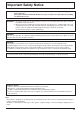
Important Safety Notice WARNING: To prevent damage which may result in fire or shock hazard, do not expose this appliance to rain or moisture. Do not place containers with water (flower vase, cups, cosmetics, etc.) above the set. (including on shelves above, etc.) WARNING: 1) To prevent electric shock, do not remove cover. No user serviceable parts inside. Refer servicing to qualified service personnel. 2) Do not remove the earthing pin on the power plug.
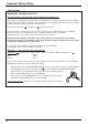
Important Safety Notice FOR UK ONLY IMPORTANT: THE MOULDED PLUG FOR YOUR SAFETY, PLEASE READ THE FOLLOWING TEXT CAREFULLY. This appliance is supplied with a moulded three pin mains plug for your safety and convenience. A 5 amp fuse is fitted in this plug. Shall the fuse need to be replaced, please ensure that the replacement fuse has a rating of 5 amps and that it is approved by ASTA or BSI to BS1362. Check for the ASTA mark ASA or the BSI mark on the body of the fuse.
Safety Precautions WARNING Setup This Plasma Display is for use only with the following optional accessories. Use with any other type of optional accessories may cause instability which could result in the possibility of injury. • • • • • • (All of the following accessories are manufactured by JVC) ................................................... Speakers TS-C5000SPG Stand Unit ................................................. TS-C50P1G Video Input Card .......................................
Safety Precautions If problems occur during use If a problem occurs (such as no picture or no sound), or if smoke or an abnormal odour starts to come out from the Plasma Display, immediately unplug the power cord plug from the wall outlet. If you continue to use the Plasma Display in this condition, fire or electric shock could result. After checking that the smoke has stopped, contact your local JVC dealer so that the necessary repairs can be made.
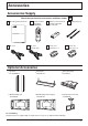
Accessories Accessories Supply Check that you have the accessories and items shown Operating Instruction book Remote Control Transmitter EUR646526 Fixing bands × 2 Batteries for the Remote Control Transmitter (2 × R6 Size) INPUT SURROUND VOL N R PICTURE GD-V501PCE SOUND SET UP PICTURE POS.
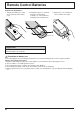
Remote Control Batteries Requires two R6 batteries. 1. Turn the transmitter face down. Press and slide off the battery cover. 2. Install the batteries as shown in the battery compartment. (Polarity + or – must match the markings in the compartment.) 3. Replace the cover and slide in reverse until the lock snaps. Two "R6" size Helpful Hint: For frequent remote control users, replace old batteries with Alkaline batteries for longer life.
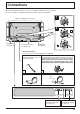
Connections When connecting the speakers, be sure to use only the optional accessory speakers. Refer to the speaker’s Installation Manual for details on speaker installation. 1 Speakers (Optional accessories) 2 1 SPEAKERS Terminals (R) AC cord connection (see page 14) SPEAKERS Terminals (L) 2 – Cable fixing bands Secure any excess cables with bands as required. Pass the attached cable fixing band through the clip as shown in the figure.
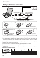
Connections PC Input Terminals connection COMPUTER AUDIO PC IN POWER / R - STANDBY INPUT – VOL + G POWER ON Conversion adapter (if necessary) Less than 3" 15/16 (10 cm) Ferrite core (large size) (supplied) D-sub 15p RGB PC cable Less than 3" 15/16 (10 cm) Ferrite core (small size) (supplied) Audio Stereo plug Connect a cable which matches the audio output terminal on the computer.
Connections SERIAL Terminals connection The SERIAL terminal is used when the Plasma Display is controlled by a computer. COMPUTER 6 1 RS-232C straight cable Ferrite core (large size) (supplied) SERIAL 7 2 8 3 9 4 5 Pin layout for RS-232C Installing the ferrite core (Large size) Less than 3" 15/16 (10 cm) D-sub 9p Open Notes: (1) Use the RS-232C cable to connect the computer to the Plasma Display. (2) The computer shown is for example purposes only.
Basic Controls INPUT R - STANDBY G POWER ON Main Power On/Off Switch Power Indicator The Power Indicator will light. Power-OFF... Indicator not illuminated (The unit will still consume some power as long as the power cord is still inserted into the wall outlet.) Stand-by .... Red Power-ON ..... Green • • • – VOL INPUT button (AV(S Video), Component/RGB and PC Mode Selection) Press the “INPUT” button to select AV (S Video), Component/RGB and PC input signal modes sequentially.
Basic Controls Explanations from here onward describe the functions when the optional Video Input Card is installed. SURROUND button (see page 23) INPUT button (AV(S Video), Component/RGB and PC Mode Selection) Press to select AV(S Video), Component/RGB and PC input signal modes sequentially. (see page 15) Sound mute On/Off (see page 22) INPUT Volume Adjustment Press the Volume Up “+” or Down “–” button to increase or decrease the sound volume level.
Power On/Off and input signal selection AC cord connection Connecting the AC cord plug to the Plasma Display. Power On/Off Connecting the plug to the Wall Outlet Note: Main plug types vary between countries. The power plug shown at left may, therefore, not be the type fitted to your set. R - STANDBY INPUT — VOL Press the Power switch on the Plasma Display to turn the set on : Power-On.
Power On/Off and input signal selection Select the input signal INPUT Press the INPUT button to select the input signal to be played back from the equipment which has been connected to the Plasma Display. R - STANDBY INPUT — VOL Select the input signals to be connected by installing the optional Video Input Card.
On-Screen Menu Display from Remote Control To Picture adjust menu (see page 24) Press to select each item.
On-Screen Menu Display from Remote Control Press to access each adjust screen. R Press the R buttun to return to “Setup” menu. To Signal screen for AV (see page 30, 31) To Signal screen for Component (see page 31) [ AV ] Signal 3D Y/C Filter (NTSC) Colour system 3:2 Pulldown Aspect Auto (4:3 ) On Auto Off 4:3 To Signal screen for RGB (see page 32) [ Component ] Signal 3:2 Pulldown [ RGB ] Signal H&V Sync Off H-Freq. V-Freq.
ASPECT Controls The Plasma Display will allow you to enjoy viewing the picture at its maximum size, including wide screen cinema format picture. ASPECT INPUT VOL N R PICTURE POS. /SIZE PC SOUND SET UP ASPECT OFF TIMER PLASMA DISPLAY 18 4:3 Zoom Auto SURROUND PICTURE ASPECT button The aspect mode changes each time the ASPECT button is pressed. 16 : 9 Just Notes: (1) During RGB and PC input signal modes, the mode switches between “4:3”, “Zoom” and “16:9” only.
ASPECT Controls Explanation Picture Mode 4:3 will display a 4:3 picture at its standard 4:3 size. 4 4:3 4:3 3 4 Zoom mode magnifies the central section of the picture. 16 Zoom Zoom 3 4 9 16:9 will display the picture at its maximum size but with slight elongation. 16 16 : 9 16 : 9 3 4 9 16 Just Just 3 4 9 16 Auto 3 For an elongated image Auto 9 Image is expanded 4 3 For a 4:3 image Changes in accordance with the Aspect Auto mode setting (see page 31).
Adjusting Picture Pos./Size Adjusting screen 1 PICTURE POS. /SIZE Press to display the Picture Pos./Size menu. INPUT SURROUND 2 Press to select H-Pos/H-Size/V-Pos/VSize/Clock Phase. VOL N During “AV(S Video)” and “Component” input signal modes. Picture Pos./Size Normalise H-Pos H-Size V-Pos V-Size During “RGB” and “PC” input signal modes. Picture Pos./Size Normal 3 Normal Normalise H-Pos H-Size V-Pos V-Size Clock Phase R PICTURE PICTURE POS.
Adjusting Picture Pos./Size When the Position Left “ ” button is pressed. When the Position Right “ ” button is pressed. H-Pos When the Position Left “ ” button is pressed. When the Position Right “ ” button is pressed. H-Size When the Position Left “ ” button is pressed. When the Position Right “ ” button is pressed. V-Pos When the Position Left “ ” button is pressed. When the Position Right “ ” button is pressed.
Sound Adjustment 1 SOUND Press to display the Sound menu. INPUT SURROUND 2 Select to adjust each item. VOL Press to select the desired adjustment menu. N R Select the desired level by listening to the sound. PICTURE SOUND PICTURE POS /SIZE Bass Adjusts low sounds Treble Adjusts high sounds Balance Adjusts left and right volumes SET UP ASPECT Sound Normalise Sound Mode Bass Treble Balance Surround Normal Normal Emits the original sound.
Surround Controls SURROUND INPUT SURROUND Button The benefits of surround sound are enormous. You can be completely enveloped in sound; just as if you were at a concert hall or cinema. The surround setting switches on and off each time the SURROUND button is pressed. On SURROUND Off VOL N R PICTURE SOUND SET UP Surround PICTURE POS. /SIZE PC ASPECT On Note: The surround settings are memorized separately for each Sound mode (Normal, Auto).
Picture Adjustments 1 PICTURE Press to display the Picture menu. Picture 2 Select to adjust each item. Press to select the menu to adjust. Select the desired level by looking at the picture behind the menu. Press the left modes. Picture Normal Normalise Picture Mode Contrast Brightness Colour Tint Sharpness White balance Advanced settings Normal Normal 20 0 0 0 0 Normal On button to switch between Normal 20 0 0 0 0 Dynamic Cinema Normal For viewing in standard (evening lighting) environments.
Picture Adjustments Item Effect Adjustments Contrast Less More Brightness Darker Brighter Adjusts for easier viewing of dark pictures such as night scenes and black hair. Adjusts colour saturation. Colour Less Tint (NTSC only) Selects the proper brightness and density for the room. More Adjust for nice skin colour. Reddish Greenish Adjusts picture sharpness. Sharpness Less More Notes: (1) “Colour” and “Tint” settings cannot be adjusted for “RGB” and “PC” input signal modes.
Set up TIMER The timer can switch the Plasma Display On or Off. Before attempting Timer Set, confirm the PRESENT TIME and adjust if necessary. Then set POWER ON Time / POWER OFF Time. Display the Set up TIMER screen. 1 SET UP Press to display the Setup menu screen. INPUT Setup Component/RGB-in select RGB SURROUND Press to select Set up TIMER. 2 VOL Signal Screensaver English (UK) OSD Language Set up TIMER N R Set up TIMER PICTURE SOUND Press to display the Set up TIMER screen.
Setup TIMER TIMER Set Press to select POWER ON Time/POWER OFF Time. 1 Set up TIMER 0:52 Off 0:00 Off 0:00 PRESENT TIME POWER ON Function POWER ON Time POWER OFF Function POWER OFF Time Press to display the POWER ON Setup/ POWER OFF Setup screen. 2 Press to select Hours Adjustment/ Minutes Adjustment. POWER ON Setup Press to adjust each time. POWER ON Time Hours Adjustment Minutes Adjustment 0 : 52 00 52 POWER OFF Setup Press to complete POWER ON Time/ POWER OFF Time.
Screensaver (For preventing after-images) Do not display a still picture, especially in 4:3 mode, for any length of time. If the display must remain on, a Screensaver should be used. 1 SET UP Press to display the Setup menu screen. Setup Press to select the Screensaver. 2 Component/RGB-in select RGB Signal Screensaver English (UK) OSD Language Set up TIMER Press to select the Screensaver screen. Reversal / Scroll selection 3 Press to select the Function.
Screensaver (For preventing after-images ) Setup of Screensaver Time Press to select Start Time/ Finish Time (When Time Designation is selected). Press to select Periodic Time/ Operating Time (When Interval is selected). 5 Start Time Start Ttime Hours Adjustment Minutes Adjustment Finish Time Press to select each Time Adjustment screen.
Setup for Input Signals Component/RGB-in Select Select the input signals to be connected by installing the Optional Video Input Card. (Refer to the service manual for the optional Video Input Card.) Select to match the signals from the source connected to the Component/RGB input terminals. “Component” Y, PB, PR signals R, G, B, HD, VD signals “RGB” 1 SET UP Press to display the Setup menu screen. INPUT Press to select the “Component/RGB-in Select”. 2 SURROUND VOL N Press to select the desired mode.
Setup for Input Signals Colour system / Aspect Auto Select Signal from the “Setup” menu during AV(S Video) input signal mode. (“Signal [AV]” menu is displayed.) Setup Component/RGB-in select RGB Signal Screensaver Press to select the “Colour system” or “Aspect Auto”. Set up TIMER Press to select each functions. If the picture image becomes unstable: With the system set on Auto, under conditions of low level or noisy input signals the image may in rare cases become unstable.
Setup for input signals Sync Setup Select Signal from the “Setup” menu during RGB or PC input signal mode. Component/RGB-in select RGB Signal Screensaver Press to adjust. English (UK) OSD Language Set up TIMER Press (ACTION) button [ RGB ] Signal H&V Sync H-Freq. V-Freq. R 31.5 kHz 60.0 Hz Press to exit from adjust mode. [ PC ] Signal H&V Sync H-Freq. V-Freq. 31.5 kHz 60.0 Hz Setting RGB sync signal: Confirm that the input is set to RGB input (this setting is valid only for RGB input).
Troubleshooting Before you call for service, determine the symptoms and make a few simple checks as shown below. Symptoms Picture Checks Sound Electrical Appliances Cars/Motorcycles Fluorescent light Interference Noisy Sound Volume (Check whether the mute function has been activated on the remote control.
Connections Connection to the Optional Video Input Card. (IF-C50P1G) By installing the optional Video Input Card, the Plasma Display can handle high quality input signals such as AV (S Video), DVD, and RGB. Below is the connecting method when the optional Video Input Card is installed.
Connections AV Input Terminals connection Connect the signal source equipment. (Example) When connecting an S VIDEO VCR.
Connections (Example) When connecting 21 pin scart cables. (VCR) AV2 Video input to BNC socket Audio input to L/R sockets (DVD / Satellite Receiver) R L AUDIO IN S VIDEO IN VIDEO IN AV AV1/TV Video input to BNC socket RCA-BNC adapter plug Audio input to L/R sockets Notes: (1) Additional equipment, cables and an adaptor plug shown are not supplied with this set. (2) 21 pin connectors and 21 pin scart plugs are connectors used in Europe.
Connections Component/RGB Input connection Component signals (Y, PB, PR) connection RCA-BNC adaptor plug (DVD Player) Y Y, PB, PR PB 3×RCA video cables PR L AUDIO R 2×RCA audio cables R L AUDIO VD HD PR/CR/R PB/CB/B Y/G COMPONENT/RGB IN Notes: (1) Change the “Component/RGB-in” setting in the “Setup” menu to “Component”. (see page 30) (2) Additional equipment, cables and adaptor plugs shown are not supplied with this set.
Specifications GD-V501PCE Power Source Power Consumption 220 - 240 V AC, 50Hz/60Hz Normal use Stand-by condition Power off condition Plasma Display panel Contrast Ratio Screen size 495 W 3.0 W 1.7 W Drive method AC type 50-inch, 16:9 aspect ratio 3000:1 1,106 mm (W) × 622 mm (H) × 1,269 mm (diagonal) No.
Specifications GD-V501PCE Optional Supplied Speakers Stand Unit Video Input Card TS-C5000SPG TS-C50P1G IF-C50P1G TS-C50P6G TS-C50P2G Wall Mounting Unit Wall Mounting Unit (angled) Ceiling Suspension Unit TS-C50P3G 1,210mm × 724 mm × 98 mm Dimensions (W × H × D) 98 mm 724 mm 1,210 mm POWER / R - STANDBY INPUT – VOL + G POWER ON Mass (Weight) approx. 42.5 kg net (main unit only) approx. 47.1 kg (with speakers) Notes: (1) Design and specifications are subject to change without notice.
GD-V501PCE PLASMA DISPLAY MONITOR VICTOR COMPANY OF JAPAN, LIMITED © 2003 VICTOR COMPANY OF JAPAN, LIMITED Printed in Japan TQZW243