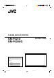
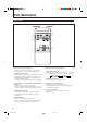
PLASMA DISPLAY MONITOR GM-P421U GM-P420UG INSTRUCTIONS For Customer Use: Enter below the Model No. and the Serial No. which is located on the rear panel of the cabinet. Retain this information for future reference. Model No. Serial No. MENU INPUT POWER LCT1071-001B Cover.GM-P420[US]f 3 02.5.
Cover.GM-P420[US]f 4 02.4.
INSTRUCTIONS Thank you for purchasing this JVC Monitor. Before using the monitor, read this manual carefully so that you know how to use the Monitor correctly. Refer to this manual whenever questions or problems about operation arise. Be sure to read and observe the safety precautions. Keep this manual where the user can see it easily. * Installation and removal require special expertise. Consult your product dealer for details.
Safety Precautions FCC NOTICE ■ GM-P420UG CAUTION: Changes or modifications not approved by JVC could void the user’s authority to operate the equipment. NOTE: This equipment has been tested and found to comply with the limits for a Class A digital device, pursuant to Part 15 of the FCC Rules. These limits are designed to provide reasonable protection against harmful interference when the equipment is operated in a commercial environment.
– When the product is used on a cart, care should be taken to avoid quick stops, excessive force, and uneven surfaces which may cause the product and cart to overturn, damaging equipment or causing possible injury to the operator. – Slots and openings in the cabinet are provided for ventilation. These ensure reliable operation of the product and protect it from overheating. These openings must not be blocked or covered.
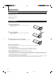
Parts Identification Remote Control 1 6 7 2 3 DISPLAY ASPECT POWER VIDEO A VIDEO B COMPO. RGB A 8 RGB B 4 MUTING VOLUME 9 p 5 MENU/EXIT RM-C576 REMOTE CONTROL UNIT 1 Remote control cable jack (page 11) Connect the remote control cable (not supplied) when using this remote control as a wired remote control.
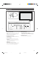
Monitor: Front View 1 2 MENU INPUT MENU INPUT Bottom View 3 1 Remote sensor/power lamp Point the front end of the wireless remote control toward here. When the Monitor is turned on, the power lamp glows green. It glows orange in standby mode. 2 Self-diagnostic lamps (page 35) These lamps light/flash if something abnormal occurs with the Monitor. 4 5 POWER POWER 6 5 INPUT button (page 14) Use this button to switch between inputs.
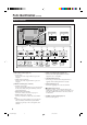
Parts Identification (Continued) Monitor: Rear Views 7 SPEAKER OUT SPEAKER OUT R L ( 1 2 3 5 OPTION AC IN RS-232C REMOTE WIRED • D-sub, 15 pin Connect to the video output terminal of a personal computer. • AUDIO IN (stereo mini jack) Connect to the audio output terminal of a personal computer. 2 REMOTE terminals (pages 11 and 13) • RS-232C (D-sub, 9 pin) Connect to the RS-232C terminal of a personal computer. For the control method using this terminal, consult an authorized JVC dealer.
8 VIDEO IN 9 VIDEO AUDIO L/MONO OUT VIDEO A R IN p VIDEO AUDIO L/MONO Y/C IN VIDEO B 8 VIDEO A terminals (page 12) • VIDEO IN terminal (BNC) Connect this terminal to the video output terminal of a VCR, etc. • VIDEO OUT terminal (BNC) Connect this terminal to the video input terminal of another Monitor. • AUDIO (L/MONO, R) input terminals (pin jack) Connect these terminals to the audio input terminals of a VCR, etc.
Preparations Checking the Accessories The following accessories are included with the Monitor. Check for them. If any item is missing, please contact the dealer where you purchased the Monitor. • Remote control (RM-C576) x 1 • Power cord x 1 • Batteries (AA/R6P) x 2 Installing the Batteries Put the batteries in the remote control as follows. If the remote control has become erratic in operation, change the batteries. 1 Remove the back cover.
Installation Precautions • When mounting the Monitor vertically, consult your dealer. (See also page 13). • When installing the Monitor, be sure to use a dedicated Stand Unit, Wall Mounting Unit, or Monitor Hanger Unit, depending on a particular case. Ask your dealer for installation. • When installing the Monitor, refer also to the user manual for each option to use. Do not tilt the Monitor rightward, leftward, or backward.
Connections Precautions • • • • • Before making connections, turn off all the equipment. Plugs should be firmly inserted; poor connection could cause noise. To unplug a cord, be sure to grasp its plug and pull it out. Connect the power cord after having finished all other connections. Refer also to the user manual of each piece of equipment. Available Signals Video signals The following signals can be input to this Monitor: • VIDEO A and VIDEO B terminals accept — NTSC, PAL M, and PAL N signals.
Connection Diagrams Typical connections Personal computer Personal computer (used as the playback source) (used to control the Monitor) Remote control Amplifier, etc. (supplied) RM-C576 REMOTE CONTROL UNIT MENU/EXIT MUTING VOLUME RGB B VIDEO A VIDEO B COMPO.
Connections (Continued) AV connections VCR 1 VCR 2 DVD player, etc (used as the playback source) (used as the playback source) (used as the playback source) IN To audio output R VIDEO A To video output VIDEO AUDIO L/MONO OUT To audio output IN To S-video output To video output To audio output To video output VIDEO VIDEO AUDIO L/MONO Y/C IN VIDEO B R Y/G Pb/B Pr/R HD/Cs AUDIO L/MONO VD R COMPONENT/RGB B When connecting another PC to the COMPONENT/RGB B terminals, set the “RGB/
Connecting an external control unit When connecting the external control unit to the MAKE terminal, you can operate the following functions through the MAKE terminal; • Turn on or off the Monitor. ON (so that the Monitor is in standby mode). Preparation: The POWER switch on the rear must be set to • Select the input. Preparation: “REMOTE SWITCH” should be set correctly to select your desired input (see page 26). Notes: • There is no remote control on/off switch.
Basic Operations Daily Operations 1 Rear View Turn on the main power. Set POWER on the back of the Monitor to ON. The POWER lamp on the upper left of the front panel glows orange. 2 Turn on the power. Press POWER on the remote control to turn the power on. The POWER lamp changes to glow green. • You can also use the POWER on the front panel (lower right) to turn on the Monitor.
Changing the Aspect Ratio With this Monitor, you can select among three types of wide screens (FULL, ZOOM, and PANORAMIC) in addition to the REGULAR screen of conventional 4:3 aspect ratio. Press ASPECT to select the screen size ASPECT DISPLAY ASPECT POWER VIDEO A VIDEO B COMPO. RGB A Each time you press the button, the screen size changes as follows: RGB B MUTING VOLUME MENU/EXIT REGULAR FULL PANORAMIC ZOOM REGULAR: Displays at conventional 4:3 aspect ratio.
Video Adjustments For video adjustments, use menus. You can use the buttons either on the remote control or on Monitor for menu operations. • Refer also to “Menu Classifications” on pages 31 and 33. Adjusting the Picture Quality Picture quality can be set for each input mode. 1 MENU INPUT POWER Press MENU/EXIT (or MENU on the Monitor) to display the Main Menu. MAIN MENU MENU INPUT Cursor (3) POWER PICTURE ADJ. SIZE/POSITION ADJ.
5 6 Press 2/3 to make adjustments. Press MENU/EXIT (or MENU on the Monitor) twice to exit from the menu operations. To make an adjustment while viewing the adjustment bar After step 3 on page 16, proceed as follows: Adjusting the Screen Size and Position The screen size and position can be adjusted. Adjusted settings can be stored for each signal type; therefore, when the same signal comes in, the stored settings are recalled.
Video Adjustments (Continued) 5 Press 2/3 to adjust the selected item. Note: • During size and position adjustments, the Monitor screen may be distorted. This is normal, but not a malfunction of the Monitor. 6 MENU INPUT MENU INPUT POWER Press MENU/EXIT (or MENU on the Monitor) twice to exit from the menu operations. To make an adjustment while viewing the adjustment bar POWER After step 3 on page 17, proceed as follows: 1 Press 5/∞ to move the cursor (3) to “sub menu.
Adjusting the Color Temperature Adjusting the White Balance The adjusted setting applies to all inputs. 1 Press MENU/EXIT (or MENU on the Monitor) to display the Main Menu. G GAIN, B GAIN and R GAIN can be finely adjusted separately for “HIGH” and “LOW” settings of the color temperature. 1 MAIN MENU Cursor (3) PICTURE ADJ. SIZE/POSITION ADJ. FUNCTION SELECT STATUS DISPLAY ENTER: 2 3 On the Monitor: Press MENU while holding 2 to display the Setup Menu.
Video Adjustments (Continued) To make an adjustment while viewing the adjustment bars After step 3 on page 19, proceed as follows: 1 Press 5/∞ to move the cursor (3) to “sub menu.” 2 Press 3 to display the Sub Menu. The Sub Menu for R GAIN appears on the screen. : 000 + R GAIN – MENU INPUT MENU INPUT 3 Press 5/∞ to select the Sub Menu you want to adjust. Each time you press the button, the Sub Menu changes as follows: R GAIN G GAIN POWER B GAIN POWER 4 Press 2/3 to adjust the selected item.
Changing the Picture Mode Changing the Aspect Ratio When one of the following signals comes in through the RGB A or COMPONENT/RGB B terminals—RGB15K-50, RGB15K-60, and VGA480-60, you can select the picture mode suited to either still pictures or moving pictures. 1 Press MENU/EXIT (or MENU on the Monitor) to display the Main Menu. The setting adjusted applies to all inputs. • You can change the aspect ratio by pressing ASPECT. (See page 15.
Video Adjustments (Continued) Setting the Receivable Signal Types You can set the receivable signal types. Normally, select “AUTO.” A common setting will apply to both the VIDEO A input and the VIDEO B input, and a different setting will apply to the COMPONENT input. 1 MENU INPUT Press MENU/EXIT (or MENU on the Monitor) to display the Main Menu. POWER MAIN MENU Cursor (3) MENU INPUT PICTURE ADJ. SIZE/POSITION ADJ.
Setting the COMPONENT/RGB B Input After connecting the playback device such as a PC or a DVD player to the COMPONENT/RGB B terminals, you have to specify which type of signal comes into this terminal—RGB or component signals. • Without setting “RGB/COMPO.” correctly, you cannot show any picture though you select the COMPONENT or RGB B input. Resetting the Function Selection Menu Settings You can reset all the Function Selection Menu settings at a time.
Other Convenient Functions To set the other convenient functions, use menus. You can use the buttons either on the remote control or on Monitor for menu operations. • Refer also to “Menu Classifications” on pages 31 and 33. Showing On-screen Display MENU INPUT The input mode and signal type will be indicated on the screen. • The following procedure can be done by using the buttons on the Monitor. You can also show these information by pressing DISPLAY on the remote control. (See page 14.
Confirming the Use Time and Model Name You can confirm the hours of use and the model name on the Setup Menu. This may be necessary when you ask for any service. 1 On the remote control: Press MENU/EXIT while holding VOLUME – to display the Setup Menu. Showing the On-screen When Changing the Input Mode With this function, you can see the selected input mode and signal type when changing the input mode. 1 On the remote control: Press MENU/EXIT while holding VOLUME – to display the Setup Menu.
Other Convenient Functions (Continued) 2 Press 5/∞ to move the cursor (3) to “CONTROL LOCK.” • The Setup Menu consists of two pages. If you keep pressing 5/∞, you can move to the other page from the current page. 3 Press 2/3 to select the desired setting. Each time you press the button, the Control Lock function alternates between “ON” and “OFF.” MENU INPUT To cancel the Control Lock function, select “OFF.
3 Press 2/3 to select the desired setting. 2 Each time you press the button, the Remote Switch Mode changes as follows: MODE1: Input alternates between “VIDEO A” and “VIDEO B” when controlled from the external control unit. MODE2: Input alternates between “VIDEO A” and “RGB B/COMPO.” when controlled from the external control unit. • The Setup Menu consists of two pages. If you keep pressing 5/∞, you can move to the other page from the current page.
Other Convenient Functions (Continued) Using the Power Save Function You can use this function to reduce the electrical consumption and to extend the lifetime of the Monitor’s screen. • The brightness of the screen will be reduced. 1 MENU INPUT On the remote control: Press MENU/EXIT while holding VOLUME – to display the Setup Menu. On the Monitor: Press MENU while holding 2 to display the Setup Menu.
2 Press 5/∞ to move the cursor (3) to “COLOR-REVERSE” (on the second page). • The Setup Menu consists of two pages. If you keep pressing 5/∞, you can move to the other page from the current page. SET-UP MENU PIXEL SHIFT POWER SAVE COLOR-REVERSE REFRESH reset all reset HOUR METER x100h MODEL NAME 3 Resetting All the Setup Menu Settings You can reset all the following Setup Menu settings at a time, except the use time of the source lamp (HOUR METER).
Other Convenient Functions (Continued) Resetting All the Menu Settings You can reset all the Menu settings and adjustments at a time, except the use time of the source lamp (HOUR METER). 1 MENU INPUT On the remote control: Press MENU/EXIT while holding VOLUME – to display the Setup Menu. On the Monitor: Press MENU while holding 2 to display the Setup Menu.
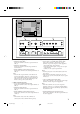
Menu Classifications Main Menu Main Menu Picture Adjustment Menu CONTRAST – VIDEO A MAIN MENU SELECT: ADJUST: EXIT: MENU BRIGHT – : +01 : 00 : –02 : 00 : 00 CONTRAST BRIGHT CHROMA PHASE SHARPNESS sub menu reset PICTURE ADJ. SIZE/POSITION ADJ. FUNCTION SELECT STATUS DISPLAY ENTER: :+01 + PICTURE ADJ. EXIT: MENU SELECT: :+01 + :+01 CHROMA – + :+01 PHASE – *2 + :+01 SHARPNESS – *1 *2 + reset Are you sure? key. "YES" then "NO" then MENU key.
Menu Classifications (Continued) PICTURE ADJ. (Picture adjustment): See page 16. CONTRAST BRIGHT CHROMA*1 PHASE*2 SHARPNESS sub menu reset Adjusts the contrast of the picture. Adjusts the brightness of the picture. Adjusts the color density of the picture. Adjusts the color phase. Adjusts the outlines of the picture. Displays the fine adjustment bar. Resets the Picture Adjustment Menu settings to defaults. SIZE/POSITION ADJ. : See page 17. H.SIZE H. POSITION V. SIZE V.
Setup Menu White Balance Adjustment Menu SET-UP MENU STATUS DISPLAY CONTROL LOCK REMOTE SWITCH HD SIGNAL MODE WHITE BALANCE ADJUST: 1/2 : : : : OFF OFF MODE1 1080i WHITE BALANCE:HIGH R GAIN G GAIN B GAIN sub menu reset : 000 :+ 001 :– 002 R GAIN – G GAIN – : 000 + :+001 + B GAIN – :–002 + EXIT: MENU SELECT: ADJUST: SELECT: EXIT: MENU reset Are you sure? key. "YES" then "NO" then MENU key.
Troubleshooting Solutions to common problems related to the Monitor are described here. If none of the solutions presented here solves the problem, unplug the Monitor and consult an authorized dealer or service center. Symptom Probable cause Power is not supplied. • Is the power cord disconnected? •Is the POWER switch turned on? Video image does not •Is the correct input selected? appear, or audio sound does not occur. Corrective action •Insert the power cord (plug) firmly. •Turn on the POWER switch.
Self-diagnostic Indication If the trouble still persists, follow the procedure below: 1 When something abnormal occurs with the Monitor, this function informs you of the condition of the Monitor with self-diagnostic lamps, allowing for smooth service work. On the Self-diagnostic Report Sheet (below), check the box next to “Lights” or “Flashes” of the corresponding lamp or lamps. • Only one lamp may light or flash, or all three lamps may do so. Remote sensor 1 2 3 2 Switch off the the Monitor.
General Specifications Model name GM-P421U GM-P420UG Frame color Silver Gray Screen size Type 42 wide format Aspect ratio 16:9 (Wide format) Number of pixels displayed 853 (H) x 480 (V) Number of colors displayed 16.77 million (256 colors for each of RGB) Effective screen size (W x H, Diagonally) 92.1 cm x 51.8 cm (36-3/8” x 20-1/2”), 105.7 cm (41-5/8”) Weight 32.3 kg (71.1 lbs.) External dimensions (W x H x D) 103.5 cm x 64.0 cm x 8.
Model name GM-P421U Input/output terminals*1 RGB A RGB input GM-P420UG D-sub 3-row 15-pin terminal x 1, Video signal: 0.7 V(p-p), 75 Ω G on sync: 1 V(p-p), 75 Ω (negative sync) Horizontal sync/Composite sync (HD/Cs): HD: 0.3 V(p-p) to 5 V(p-p), 470 Ω (positive/negative polarity) Cs: 0.
Pin assignment (Specifications for terminals) • RS-232C terminal This is a female type connector.