ENGLISH DIGITAL VIDEO CAMERA GR-D31 GR-D21 Please visit our Homepage on the World Wide Web for Digital Video Camera: http://www.jvc-victor.co.jp/english/cyber/ CONTENTS AUTOMATIC DEMONSTRATION 6 GETTING STARTED 7 – 10 TAPE RECORDING & PLAYBACK 11 – 15 ADVANCED FEATURES 16 – 33 REFERENCES 34 – 47 For Accessories: http://www.jvc-victor.co.jp/english/accessory/ INSTRUCTIONS LYT1134-001A GR-D31/21EK 01-10 1 02.12.
CONTENTS SAFETY PRECAUTIONS SOME DO’S AND DON’TS ON THE SAFE USE OF EQUIPMENT PROVIDED ACCESSORIES HOW TO ATTACH THE LENS CAP HOW TO ATTACH THE CORE FILTER AUTOMATIC DEMONSTRATION 3 4 5 5 6 6 Snapshot (For Tape Recording) ................................ 18 Auto Focus ........................................................ 18 Manual Focus .................................................... 19 Exposure Control ................................................ 19 Iris Lock .................................
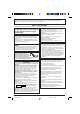
Dear Customer, Thank you for purchasing this digital video camera. Before use, please read the safety information and precautions (墌 pgs. 3 and 4) to ensure safe use of this product. SAFETY PRECAUTIONS WARNING: TO PREVENT FIRE OR SHOCK HAZARD, DO NOT EXPOSE THIS UNIT TO RAIN OR MOISTURE. CAUTIONS: ● To prevent shock, do not open the cabinet. No user serviceable parts inside. Refer servicing to qualified personnel.
Do not point the lens or the viewfinder directly into the sun. This can cause eye injuries, as well as lead to the malfunctioning of internal circuitry. There is also a risk of fire or electric shock. CAUTION! The following notes concern possible physical damage to the camcorder and to the user. When carrying, be sure to always securely attach and use the provided shoulder strap. Carrying or holding the camcorder by the viewfinder and/or the LCD monitor can result in dropping the unit, or in a malfunction.
PROVIDED ACCESSORIES or AC Adapter AP-V11E or AP-V13E Power Cord Battery Pack BN-V408U Shoulder Strap Cable Adapter Lithium Battery* CR2025 (for remote control unit) 3 2 0 w 4 3 5 e T W Remote Control Unit* RM-V718U CD-ROM Core Filter x 2 (for optional S-Video Cable and Editing Cable provided with Remote Control kit RM-V717KITU 墌 pg. 6 for attachment) 6 9 2 Lens Cap (See below for attachment) 1 4 Audio/Video Cable (ø3.
HOW TO ATTACH THE CORE FILTER Attach the Core Filter(s) (if provided with your model 墌 pg. 5) to an optional cable(s). The Core Filter reduces interference. 1 2 Stopper Release the stoppers on both ends of the Core Filter. 3 3 cm Wind once Run the cable through the Core Filter, leaving approx. 3 cm of cable between the cable plug and the Core Filter. Wind the cable once around the outside of the Core Filter as shown in the illustration. • Wind the cable so that it is not slack.
@ Power r y CHARGING THE BATTERY PACK 1 With the arrow on the battery pack pointing upward, push the battery pack slightly against the battery pack mount @, then slide up the battery pack until it locks in place. Arrow 2 Set the Power Switch y to “OFF (CHARGE)”. Connect the AC Adapter to the camcorder, then connect the Power Cord to the AC Adapter. 3 Plug the Power Cord into an AC outlet. The Battery pack POWER/CHARGE lamp r on the camcorder blinks to indicate charging has started.
● Since the AC Adapter processes electricity internally, it becomes warm during use. Be sure to use it only in well-ventilated areas. ● The following operation stops charging: • Set the Power Switch y to “PLAY”, “ ” or “ ”. • Disconnect the AC Adapter from the camcorder. • Unplug the AC Adapter from the AC outlet. • Detach the battery from the camcorder.
Shoulder Strap Attachment 1 Thread the strap through the eyelet e, then fold it back and thread it through the buckle. Repeat the procedure to attach the other end of the strap to the other eyelet e located under the Grip Strap. Confirm the strap is not twisted. Loading/Unloading A Cassette The camcorder needs to be powered up to load or eject a cassette. 1 Slide and hold OPEN/EJECT Q in the direction of the arrow then pull the cassette holder cover open until it locks.
● It takes a few seconds for the cassette holder to open. Do not apply force. ● There may be a delay after you open the cassette holder cover until the cassette holder opens. Do not use force. ● If you wait a few seconds and the cassette holder does not open, close the cassette holder cover and try again. If the cassette holder still does not open, turn the camcorder off then on again. ● If the tape does not load properly, open the cassette holder cover fully and remove the cassette.
Basic Recording $ Perform the procedures listed below before continuing. ● Power (墌 pg. 7) ● Grip Adjustment (墌 pg. 8) ● Viewfinder Adjustment (墌 pg. 8) ● Load A Cassette (墌 pg. 9) ● Recording Mode Setting (墌 pg. 10) 1 Remove the lens cap. Pull on bottom end o of LCD monitor to open. w 2 Set the Power Switch y to “ ” or “ ” while pressing down the Lock Button t located on the switch. During shooting r 180° Shooting while using the LCD monitor: Open the LCD monitor fully.
Journalistic Shooting Zooming In some situations, different shooting angles may provide more dramatic results. Hold the camcorder in the desired position and tilt the LCD monitor in the most convenient direction. It can rotate 270° (90° downward, 180° upward). To produce the zoom in/out effect, or an instantaneous change in image magnification. Zoom In Slide the Power Zoom Lever ^ towards “T”. Zoom Out Slide the Power Zoom Lever ^ towards “W”.
Time Code Normal Playback During recording, a time code is recorded on the tape. This code is to confirm the location of the recorded scene on the tape during playback. If recording starts from a blank portion, the time code begins counting from “00:00:00” (minute:second:frame). If recording starts from the end of a previously recorded scene, the time code continues from the last time code number. To perform Random Assemble Editing (墌 pg. 30 – 32), time code is necessary.
NOTES: ● If Stop mode continues for 5 minutes when power is supplied from a battery, the camcorder shuts off automatically. To turn on again, set the Power Switch y to “OFF (CHARGE)”, then to “PLAY”. ● The playback picture can be viewed in the LCD monitor, viewfinder or on a connected TV (墌 pg. 15). ● You can also view the playback picture on the LCD monitor with it flipped over and pushed against the camera body.
Connections 1 Make sure all units are turned off. 2 Connect the camcorder to a TV or VCR as shown To AV * in the illustration. Connector cover* If using a VCR . . . go to step 3. If not . . . go to step 4. 3 Connect the VCR output to the TV input, referring to your VCR’s instruction manual. 4 Turn on the camcorder, the VCR and the TV. 5 Set the VCR to its AUX input mode, and set the TV to its VIDEO mode. To choose whether or not the following displays appear on the connected TV . . . • Date/Time ...
Night-Scope Makes dark subjects or areas even brighter than they would be under good natural lighting. Although the recorded image is not grainy, it may look as if it is strobing due to the slow shutter speed. 1 Set the Power Switch y to “ ” while pressing down the Lock Button t located on the switch. Open the LCD monitor fully or pull out the viewfinder fully. 2 Press NIGHT 9 so that the Night-Scope indicator “ ” 2 appears.
Fade/Wipe Effects These effects let you make pro-style scene transitions. Use them to spice up the transition from one scene to the next. Fade or Wipe works when tape recording is started or when you stop recording. FADER — WHITE Fade in or out with a white screen. FADER — BLACK Fade in or out with a black screen. FADER — B.W 1 Set the Power Switch y to “ Fade in to a colour screen from a black and white screen, or fade out from colour to black and white. 2 Press the MENU/VOLUME wheel $ in.
Snapshot (For Tape Recording) This feature lets you record still images that look like photographs onto a tape. SNAPSHOT MODE SELECTION 1 Set the Power Switch y to “ ” while pressing down the Lock Button t located on the switch. Open the LCD monitor fully or pull out the viewfinder fully. 2 Press the MENU/VOLUME wheel $ in. The Menu Screen appears. 3 Rotate the MENU/VOLUME wheel $ to select “ (CAMERA)”, then press it. 4 Rotate the MENU/VOLUME wheel $ to select “SNAP MODE”, then press it.
Manual Focus Exposure Control To obtain correct focus. 1 If you are using the viewfinder, you should already Manual exposure adjustment is recommended in the following situations: 2 Set the Power Switch y to “ • When shooting using reverse lighting or when the background is too bright. • When shooting on a reflective natural background such as at the beach or when skiing. • When the background is overly dark or the subject light.
3 Rotate the MENU/VOLUME wheel $ to select Iris Lock Use this function in the following situations: • When shooting a moving subject. • When the distance to the subject changes (so its size in the LCD monitor or the viewfinder changes), such as when the subject is backing away. • When shooting on a reflective natural background such as at the beach or when skiing. • When shooting objects under a spotlight. • When zooming. When the subject is close, keep the iris locked.
WIPE/FADER For Recording Menu This camcorder is equipped with an easy-to-use, on-screen menu system that simplifies many of the more detailed camcorder settings (墌 pg. 21 – 24). 1 Set the Power Switch y to “ ” while pressing down the Lock Button t located on the switch. Open the LCD monitor fully or pull out the viewfinder fully. 2 Press the MENU/VOLUME wheel $ in. The Menu Screen appears. Refer to “Fade/Wipe Effects” (墌 pg. 17). PROGRAM AE Refer to “Programme AE With Special Effects” (墌 pg. 16).
SNAP MODE Refer to “Snapshot (For Tape Recording)” (墌 pg. 18). GAIN UP OFF: Allows you to shoot dark scenes with no picture brightness adjustment. [AGC]: The overall appearance may be grainy, but the image is bright. AUTO : The shutter speed is automatically adjusted (1/25 — 1/200 sec.). Shooting a subject in low or poor lighting at 1/25 sec. shutter speed provides a brighter image than in the AGC mode, but the subject’s movements are not smooth or natural. The overall appearance may be grainy.
SYSTEM “ SYSTEM” functions which are set when the Power Switch y is set to “ ” are also applied when the Power Switch y is set to “PLAY” (墌 pg. 24). S Y S TEM – MELODY B EEP – ON T ALLY – ON R EMOTE D EMO MODE – ON P R I OR I TY – LCD CAM RESET PRIORITY [LCD]: When the LCD monitor is fully open, even if the viewfinder is pulled out, the image is displayed only on the LCD monitor; it will not be displayed in the viewfinder.
VIDEO TIME CODE [OFF]: Time code is not displayed. ON: Time code is displayed on the camcorder and on the connected TV. Frame numbers are not displayed during recording. V I DEO SOUND MOD E – STEREO 12B I T MOD E – SOUND 1 – O.O SYNCHRO REC MODE – S / AV I NPUT – OF F CLOCK ADJ. Allows you to set the current date and time (墌 pg. 10). RETURN For Playback Menu The following procedure applies to all except Synchro Comp (墌 pg. 32). 1 Set the Power Switch y to “PLAY” while pressing SOUND MODE ........
VIDEO DISPLAY • Settings made in the “ VIDEO DISPLAY” Menu are effective only for tape playback. V I DEO BR I GH T ON SCR E E N DA TE / T I ME T I ME COD E D I SPLAY – LCD – OF F – OF F RETURN BRIGHT , DATE/TIME , TIME CODE Refer to “ CAMERA DISPLAY” on page 23, 24. The factory-preset of “DATE/TIME” in the “ VIDEO DISPLAY” Menu is “OFF”. NOTES: • You can also use the provided remote control’s AUDIO button R to change the output sound (without having to access the Playback Menu).
Dubbing To Or From A VCR To Use This Camcorder As A Player 1 Following the illustration, connect the camcorder and the VCR. Also refer to pg. 15. 2 Set the camcorder’s Power Switch y to “PLAY” 3. Connect the cables as shown in the illustration and load a cassette to record on. 4. Press the Recording Start/Stop button w to engage the Record-Pause mode. “ A/V IN ” appears on the screen. 5. Press the Recording Start/Stop button w to start % rotates. recording.
Dubbing To Or From A Video Unit Equipped With A DV Connector (Digital Dubbing) It is also possible to copy recorded scenes from this camcorder onto another video unit equipped with a DV connector. Since a digital signal is sent, there is little if any image or sound deterioration. To Use This Camcorder As A Player 1 Make sure all units are turned off. Connect this camcorder to a video unit equipped with a DV input connector using a DV cable as shown in the illustration. 5.
Make sure “REMOTE” in the SYSTEM Menu is set to “ON” (墌 pg. 23) and the remote control is pointed at the remote sensor 1. The transmitted beam’s approximate effective distance for indoor use is 5m. Slow-Motion Playback To allow slow-speed search in either direction during tape playback. 1 To change from normal to Slow-Motion Playback, Playback Special Effects To allow you to add creative effects to the playback image. 1 To start playback, press PLAY (4) h.
Audio Dubbing Insert Editing The audio track can be customized only when recorded in the 12-bit mode (墌 pg. 21). You can record a new scene into a previously recorded tape, replacing a section of the original recording with minimal picture distortion at the in and outpoints. The original audio remains unchanged. NOTES: ● Audio Dubbing is not possible on a tape recorded in 16-bit audio, on a tape recorded in the LP mode or on a blank portion of a tape.
IMPORTANT Random Assemble Editing [R.A.Edit] Create edited videos easily using your camcorder as the source player. You can select up to 8 “cuts” for automatic editing, in any order you like. R.A.Edit is more easily performed when the MBR (Multi-Brand Remote) is set to operate with your brand of VCR (see VCR CODE LIST), but can also be performed by operating the VCR manually. Use the optional Remote Control kit RM-V717KITU.
● Make sure to set “S/AV INPUT” to “OFF” in the Menu Screen (GR-D31 only, 墌 pg. 24). ● Set the video out select switch of the cable adapter as required: Y/C : When connecting to a TV or VCR which accepts Y/C signals and uses an S-Video cable. CVBS : When connecting to a TV or VCR which does not accept Y/C signals and uses an audio/video cable. ● When editing on a VCR equipped with a DV input connector, an optional DV cable can be connected instead of an S-Video cable and audio/video cable.
● If you select Sepia or Monotone mode from Programme AE with special effects, you cannot use the Black & White Fader. In this case the Black & White indicator begins blinking. Once the next Edit-In point is registered, the effect is turned off. To combine these effects, use Sepia or Monotone during recording, then use the Black & White Fader during Random Assemble Editing. ● It is not possible to use Fade/Wipe effects and Programme AE with special effects during Random Assemble Editing using a DV cable.
Connection To A Personal Computer It is possible to transfer video to a PC with a DV connector by using provided software, software equipped with the PC or commercially available software. 1 Make sure the camcorder and PC are turned off. 2 Connect the camcorder to your PC using the appropriate cable as shown in the illustration. To DV ! 3 Turn the camcorder’s Power Switch y to “PLAY” while pressing down the Lock Button t located on the switch and turn on the PC.
Before consulting your JVC dealer, please check the following to see it you can correct the problem yourself. The camcorder is a microcomputer-controlled device. External noise and interference (from a TV, a radio, etc.) might prevent it from functioning properly. In such cases, first disconnect its power supply unit (battery pack, AC Adapter, etc.) and wait a few minutes; and then re-connect it and proceed as usual from the beginning. No power is supplied. • The power is not connected properly.
The image looks like the shutter speed is too slow. • When shooting in the dark, the unit becomes highly sensitive to light when “GAIN UP” is set to “AUTO” in the Menu Screen. ¥ If you want the lighting to look more natural, set “GAIN UP” to “AGC” or “OFF” in the Menu Screen (墌 pg. 22). White Balance cannot be activated. • The Sepia or Monotone mode is activated. ¥ Turn off Sepia or Monotone before setting White Balance (墌 pg. 16, 20).
The LCD monitor image is distorted. • During playback of the unrecorded portion, High-speed Search and still playback, LCD monitor indications appear distorted. This is not a defect. Images on the LCD monitor are jittery. • The speaker volume is too great. ¥ Turn the speaker volume down (墌 pg. 13). There is no playback picture on the connected TV. • Since the analogue input mode is engaged, the camcorder is in the Record-Standby mode. ¥ Set “S/AV INPUT” to “OFF” in the Menu Screen (墌 pg. 24).
Battery Packs The supplied battery pack is a lithium-ion battery. Before using the supplied battery pack or an optional battery pack, be sure to read the following cautions: 1. To avoid hazards . . . Terminals ... do not burn. ... do not short-circuit the terminals. When transporting, make sure the provided battery cap is attached to the battery. If the battery cap is misplaced, carry the battery in a plastic bag. ... do not modify or disassemble. ...
4. To protect the unit, DO NOT . . . ... allow it to become wet. ... drop the unit or strike it against hard objects. ... subject it to shock or excessive vibration during transportation. ... keep the lens directed at extremely bright objects for long periods. ... expose the lens to direct sunlight. ... carry it by holding the LCD monitor or the viewfinder. ... swing it excessively when using the shoulder strap or the grip. 5. Dirty heads can cause the following problems: About moisture condensation . . .
Connectors Camcorder S-Video Output General Power supply : DC 11.0 V (Using AC Adapter) DC 7.2 V (Using battery pack) Power consumption LCD monitor off, viewfinder on : Approx. 3.4 W LCD monitor on, viewfinder off : Approx. 4.7 W Dimensions (W x H x D) : 69 mm x 94 mm x 143 mm (with the LCD monitor closed and the viewfinder pushed back in) Weight : Approx. 525 g Operating temperature : 0°C to 40°C Operating humidity : 35% to 80% Storage temperature : –20°C to 50°C Pickup : 1/6" CCD Lens : F 1.6, f = 2.
Controls, Connectors And Indicators Refer to this diagram while reading the instructions. 1 4 5 67 LCD monitor Stereo microphone 2 3 Viewfinder Speaker $ % ^ & *() 9 0 ! ui @ # o p q w Q e W r t OFF (CHARGE) PLAY y E R T Y U I O P 6 0 9 2 w 4 3 5 e T W Remote Control EN 40 INDEX GR-D31/21EK 34-48_Japan 40 02.12.
1 • Remote Sensor W Infrared Beam Transmitting Window The transmitted beam’s approximate effective distance for indoor use is 5m. The transmitted beam may not be effective or may cause incorrect operation outdoors or when the remote sensor is directly exposed to sunlight or powerful lighting. • Camera Sensor Be careful not to cover this area, a sensor necessary for shooting is built-in here. 2 Grip Strap .................................................... 墌 pg. 8 3 Tally Lamp ...........................
LCD Monitor/Viewfinder Indications During Tape Recording 0 ! 9 @ # $ 1 1h50m 40 x W 2 4 6 T REC 6w 3 % & ^ 3 5 * 7 SOUND 1 2 b i t 8 1 5 : 55 w ( 25 . 12 . 03 17 : 30 q ) During Tape Playback e r t 12 b i t / SOUND 1 L y 64 6w BLANK SEARCH u VOLUME 25 . 12 . 03 17 : 30 116 : 21 : 24 p o i EN 42 INDEX GR-D31/21EK 34-48_Japan 42 02.12.
1 Appears when the Power Switch is set to “ ” .................................................................. 墌 pg. 12 2• • : Appears when Night-Scope is engaged ..................................................... 墌 pg. 16 : Appears when “GAIN UP” is set to “AUTO” and the shutter speed is being automatically adjusted ................................ 墌 pg. 22 3 Appears when the white balance is adjusted .................................................................. 墌 pg.
WARNING INDICATIONS (high) INSERT ERROR! (exhausted) Displays the battery remaining power level. As the battery power comes close to nil, the battery indicator blinks (battery power warning). When the battery power is exhausted, power turns off automatically. (墌 pg. 9) Appears when no tape is loaded. CHECK TAPE’S ERASE PROTECTION TAB Appears when the erase protection tab is set to “SAVE” while the Power Switch y is set to “ ” or “ ”. (墌 pg.
1 Infrared Beam Transmitting Window Using The Optional RM-V717U Remote Control Unit Transmits the beam signal. The RM-V717U remote control unit is provided with the optional Remote Control kit RM-V717KITU, that also contains the Editing Cable required for Random Assemble Editing (墌 pg. 31). 2 Zoom (W) Button* 3 Zoom (T) Button* 4 DISPLAY Button* 5 SHIFT Button ...................................... 墌 pg.
A I AC Adapter ................................................... 墌 pg. 7, 8 Icons ...................................................... 墌 pg. 21 – 25 Audio Dubbing ................................................ 墌 pg. 29 Iris .................................................................. 墌 pg. 20 Analogue Input ......................................... 墌 pg. 24, 26 Auto Date ....................................................... 墌 pg. 23 Auto Focus ............................................
S Self-Recording ............................................... 墌 pg. 12 Sepia .............................................................. 墌 pg. 16 Set Remote Control/VCR Code ..................... 墌 pg. 30 Shuttle Search ............................................... 墌 pg. 13 Shutter Speed ................................................ 墌 pg. 16 Slow-Motion Playback .............................. 墌 pg. 13, 28 Snapshot ........................................................ 墌 pg.
VICTOR COMPANY OF JAPAN, LIMITED COPYRIGHT© 2003 VICTOR COMPANY OF JAPAN, LTD. GR-D31/21EK 34-48_Malaysia 48 EK 02.12.