ENGLISH CONTENTS AUTOMATIC DEMONSTRATION 7 GETTING STARTED 8 – 13 DIGITAL VIDEO CAMERA GR-DVL100 Please visit our Homepage on the World Wide Web and answer our Consumer Survey (in English only): http://www.jvc-victor.co.jp/english/index-e.html RECORDING 14 – 30 Basic Recording ................................. 14 Advanced Features ............................ 21 PLAYBACK 31 – 37 Basic Playback .................................. Advanced Features ............................ Basic Connections ......
EN Dear Customer, Thank you for purchasing this digital video camera. Before use, please read the safety information and precautions contained in the following pages to ensure safe use of this product. Using This Instruction Manual • All major sections and subsections are listed in the Table Of Contents on the cover page. • Notes appear after most subsections. Be sure to read these as well. • Basic and advanced features/operation are separated for easier reference. It is recommended that you . . . ...
EN IMPORTANT PRODUCT SAFETY INSTRUCTIONS Electrical energy can perform many useful functions. But improper use can result in potential electrical shock or fire hazards. This product has been engineered and manufactured to assure your personal safety. In order not to defeat the built-in safeguards, observe the following basic rules for its installation, use and servicing. ATTENTION: Follow and obey all warnings and instructions marked on your product and its operating instructions.
EN USE SERVICING 1. Accessories 1. Servicing To avoid personal injury: • Do not place this product on an unstable cart, stand, tripod, bracket or table. It may fall, causing serious injury to a child or adult, and serious damage to the product. • Use only with a cart, stand, tripod, bracket, or table recommended by the manufacturer or sold with the product. • Use a mounting accessory recommended by the manufacturer and follow the manufacturer’s instructions for any mounting of the product.
EN SAFETY PRECAUTIONS 5 Do not point the lens or the viewfinder directly into the sun. This can cause eye injuries, as well as lead to the malfunctioning of internal circuitry. There is also a risk of fire or electric shock. CAUTION! The following notes concern possible physical damage to the camcorder and to the user. When carrying, be sure to always securely attach and use the provided shoulder strap.
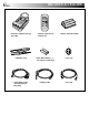
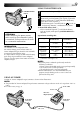
PROVIDED ACCESSORIES EN •AC Power Adapter/Charger AA-V40U • Remote Control Unit RM-V715U • Battery Pack BN-V408U • Shoulder Strap •AAA (R03) Battery x 2 (for remote control unit) •Lens Cap •Audio/Video Cable (ø3.
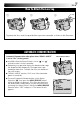
EN How To Attach The Lens Cap 1 2 3 To protect the lens, attach the provided lens cap to the camcorder as shown in the illustration. AUTOMATIC DEMONSTRATION Automatic Demonstration takes place when “DEMO. MODE” is set to “ON” (factory-preset). 䡲 Available when the Power Switch is set to “ ” or “ ” and no cassette is in the camcorder. 䡲 Performing any operation during the demonstration stops the demonstration temporarily.
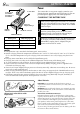
GETTING STARTED EN Power To AC outlet Battery pack BN-V408U, BN-V416U or BN-V428U CHARGING THE BATTERY PACK AC Power Adapter/Charger POWER indicator This camcorder’s 2-way power supply system lets you choose the most appropriate source of power. Do not use provided power supply units with other equipment. DC OUT connector 1 Make sure you unplug the camcorder’s DC cord from the AC Power Adapter/Charger. Plug the AC Adapter/ Charger’s power cord into an AC outlet. The POWER indicator lights.
EN 9 USING THE BATTERY PACK BATTERY RELEASE Button 1 3 1 2 2 Tilt the viewfinder upward 1. With the arrow on the battery pack pointing downward, push the battery pack slightly against the battery pack mount 2, then slide down the battery pack until it locks in place 3. •If the battery pack is attached with its mark set in the wrong direction, a malfunction may occur. To Detach The Battery Pack. . . ....
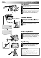
GETTING STARTED (cont.) EN Grip Adjustment 1 2 3 Power Zoom Lever Recording Start/Stop button Separate the Velcro strip. Pass your right hand through the loop and grasp the grip. Adjust so that your thumb and fingers can easily operate the Recording Start/Stop Button and Power Zoom Lever. Refasten the Velcro strip. Power Switch Viewfinder Adjustment Diopter Adjustment Control 1 Set the Power Switch to “ ” or “ ” while pressing down the Lock Button located on the switch.
EN 11 Date/Time Settings MENU/BRIGHT Wheel The date/time is recorded onto the tape at all times, but its display can be turned on or off during playback (墌 pg. 32). Power Switch Power lamp OFF Lock Button PLAY Display W I P E – S CRO L L W I P E – S HU T T E R RANDOM OF F F AD E R –WH I T E F AD E R – B L ACK F AD E R –MOS A I C D I S P L A Y ME NU 1R E T URN ON S CR E E N DA T E / T I ME T I ME COD E C L OCK AD J.
GETTING STARTED (cont.) EN Erase protection tab* Loading/Unloading A Cassette The camcorder needs to be powered up to load or eject a cassette. Cassette holder Make sure the window side is facing out. 1 Slide and hold OPEN/EJECT in the direction of the arrow then pull the cassette holder cover open until it locks. The cassette holder opens automatically. •Do not touch internal components. OPEN/EJECT Switch 2 Insert or remove a tape and press “PUSH HERE” to close the cassette holder.
EN 13 Recording Mode Setting MENU/BRIGHT Wheel Set the tape recording mode depending on your preference. Power Switch Power lamp OFF Lock Button PLAY Display CAME RA MENU 1R E T URN R E C MOD E SOUND MOD E Z OOM GA I N U P TAL L Y I D NUMB E R D EMO . MOD E SP LP Menu Screen Sub Menu 1 Set the Power Switch to “ ” while pressing down the Lock Button located on the switch. The power lamp lights and the camcorder is turned on. 2 3 4 Press the MENU/BRIGHT wheel. The Menu Screen appears.
RECORDING Basic Recording EN Power Switch Lock Button AY OFF PL Power lamp Recording Start/Stop Button NOTE: You should already have performed the procedures listed below. If not, do so before continuing. ● Power ( 墌 pg. 8) ● Grip Adjustment ( 墌 pg. 10) ● Viewfinder Adjustment ( 墌 pg. 10) ● Load A Cassette ( 墌 pg. 12) ● Recording Mode Setting ( 墌 pg.
EN 15 Power Switch Position (Manual) : Allows you to set various recording functions using the Menus. If you want more creative capabilities than Full Auto recording, try this mode. (Full Auto) : Allows you to record using NO special effects or manual adjustments. Suitable for standard recording. OFF : Allows you to switch off the camcorder. : Allows you to play back a recording on the tape. F . AUTO When the Power Switch is set to “ ”, “F. AUTO” appears. When set to “ ” or “ ”, there is no indication.
RECORDING Basic Recording (cont.) EN Power Switch Lock Button Snapshot This feature lets you record still images that look like photographs onto a tape. SNAPSHOT Button AY OFF PL SNAPSHOT MODE SELECTION MODE Button 1 2 Set the Power Switch to “ ” or “ ” while pressing down the Lock Button located on the switch. Choose the appropriate Snapshot mode from the 5 available by repeatedly pressing MODE until the desired snapshot mode indicator appears.
EN FRAME Snapshot mode with frame* FULL Snapshot mode with no frame* MULTI-4 Multi-Analyzer 4 MULTI-9 Multi-Analyzer 9 PIN-UP Pin-Up mode* * There is the sound effect of a shutter closing. 17 NOTES: ● Even if “MULTI-4” or “MULTI-9” is engaged, Snapshot recording will be performed in the FULL mode during Digital Zoom. ● If Snapshot recording is not possible, “PHOTO” blinks when SNAPSHOT is pressed. ● If Program AE with special effects ( 墌 pg.
RECORDING Basic Recording (cont.) EN Zoom in (T: Telephoto) 1 xW FEATURE: Zooming PURPOSE: T 1 0 xW T 20xW T 40xW T To produce the zoom in/out effect, or an instantaneous change in image magnification. OPERATION: Zoom out (W: Wide angle) Zoom display 1 0 xW T Digital zoom zone 10X (optical) zoom zone Approximate zoom ratio Power Zoom Lever Power Switch Zoom In Slide the Power Zoom Lever towards “T”. Zoom Out Slide the Power Zoom Lever towards “W”.
EN 19 NOTE: Recording From The Middle Of A Tape Time Code During recording, a time code is recorded on the tape. This code is to confirm the location of the recorded scene on the tape during playback. If recording starts from a blank portion, the time code begins counting from “00:00:00” (minute:second:frame). If recording starts from the end of a previously recorded scene, the time code continues from the last time code number. To perform Random Assemble Editing (墌 pg. 43 – 48), time code is necessary.
RECORDING Basic Recording (cont.) EN FEATURE: Video Light PURPOSE: To brighten the scene when natural lighting is too dim. OPERATION: LIGHT OFF/AUTO/ON Switch (Open the LCD monitor to access this switch.) DANGER 䡲 The video light can become extremely hot. Do not touch it either while in operation or soon after turning it off, otherwise serious injury may result.
RECORDING Advanced Features Focus detection zone While focusing on a further subject EN 21 While focusing on a nearer subject FEATURE: Auto Focus PURPOSE: The camcorder’s Full Range AF system offers continuous shooting ability from close-up (as close as approx. 5 cm (2") to the subject) to infinity. However, correct focus may not be obtainable in the situations listed below (in these cases use manual focusing): •When two subjects overlap in the same scene. •When illumination is low.
RECORDING Advanced Features (cont.) EN Power Switch MENU/BRIGHT Wheel OFF Lock Button PLAY Display FAD E R / W I P E 4 Menu Screen W I P E – S CRO L L W I P E – S HU T T E R RANDOM OF F F AD E R –WH I T E F AD E R – B L ACK F AD E R –MOS A I C CAME RA MENU 1R E T URN R E C MOD E SOUND MOD E Z OOM GA I N U P TAL L Y I D NUMB E R D EMO .
EN 23 Menu Screen Explanations FADER/WIPE Refer to “Fade/Wipe Effects” (墌 pg. 26, 27). P.AE/EFFECT Refer to “Program AE With Special Effects” (墌 pg. 28). EXPOSURE Refer to “Exposure Control” and “Iris Lock” (墌 pg. 29). W.BALANCE Refer to “White Balance Adjustment” and “Manual White Balance Operation” (墌 pg. 30). REC MODE Allows you to set the recording mode (SP or LP) depending on your preference (墌 pg. 13).
EN Menu Screen Explanations (cont.) ON Demonstrates certain functions such as Program AE with special effects, etc., and can be used to confirm how these functions operate. When “DEMO. MODE” is set to “ON” and the Menu Screen is closed, demonstration starts. Performing any operation during the demonstration stops the demonstration temporarily. If no operation is performed for more than 1 minute after that, the demonstration will resume.
DISPLAY MENU MANUAL MENU EN 25 ON Helps cut down on noise created by wind. “ sound will change. This is normal. OFF Disengages the function which cuts down on noise created by wind. CAM RESET CANCEL Does not reset all settings to the factory-preset. ON SCREEN LCD Keeps the camcorder’s display (except the date, time and time code) from appearing on the connected TV screen. LCD/TV Makes the camcorder’s display appear on screen when the camcorder is connected to a TV.
RECORDING Advanced Features (cont.) EN Fade/Wipe Effects These effects let you make pro-style scene transitions. Use them to spice up the transition from one scene to the next. You can also vary transitions from scene to scene. IMPORTANT: Some Fade/Wipe Effects cannot be used with certain modes of Program AE with special effects ( 墌 pg. 28). If an unusable Fade/Wipe Effect is selected, its indicator blinks or goes out.
EN 27 Fader And Wipe Menu Menu FADER — WHITE FADER — BLACK FADER — MOSAIC Effect Fade in or out with a white screen. Fade in or out with a black screen. Fade in or out with a full-screen mosaic effect. FADER — B.W Fade in to a color screen from a black and white screen, or fade out from color to black and white. WIPE — CORNER Wipe in on a black screen from the upper right to the lower left corner, or wipe out from lower left to upper right, leaving a black screen.
RECORDING Advanced Features (cont.) EN IMPORTANT: Some modes of Program AE with special effects cannot be used with certain Fade/Wipe Effects ( 墌 pg. 27). If an unusable mode is selected, its indicator blinks or goes out. MENU/BRIGHT Wheel Power Switch Display P. A E / E F F E C T Menu Screen S L OW 4 x S L OW 1 0 x V I D EO E CHO 4 OF F 1/60 S HU T T E R 1/60 1/100 S HU T T E R 1/100 1/250 S HU T T E R 1/250 TWILIGHT Makes evening scenes look more natural. White Balance (墌 pg.
EN 29 Exposure Control Iris Lock Manual exposure adjustment is recommended in the following situations: • When shooting using reverse lighting or when the background is too bright. • When shooting on a reflective natural background such as at the beach or when skiing. • When the background is overly dark or the subject light. Use this function in the following situations: • When shooting a moving subject.
EN RECORDING Advanced Features (cont.) White Balance Adjustment Manual White Balance Operation A term that refers to the correctness of color reproduction under various lighting. If the white balance is correct, all other colors will be accurately reproduced. The white balance is usually adjusted automatically. However, more advanced camcorder operators control this function manually to achieve a more professional color/tint reproduction.
PLAYBACK Basic Playback Play/Pause Button (4/6) Rewind Button (2) Fast-Forward Button (3) Stop Button (5) Power Zoom Lever (VOL.) EN 1 2 31 Load a tape (墌 pg. 12). Set the Power Switch to “ ” while pressing down the Lock Button located on the switch. To start playback, press 4/6. • To stop playback, press 5. • Press 2 to rewind, or 3 to fast-forward the tape during Stop mode. To Control The Speaker Volume . . . .... slide the Power Zoom Lever (VOL.
PLAYBACK Advanced Features EN PL Power Switch OFF AY Lock Button MENU/BRIGHT Wheel Recording Start/Stop Button Display 1 2 3 Set the Power Switch to “ ” while pressing down the Lock Button located on the switch. 4 Rotate the MENU/BRIGHT wheel to select the desired function, and press it to display the Sub Menu. 5 6 Rotate the MENU/BRIGHT wheel to select the desired parameter and press it. Selection is complete. Press the MENU/BRIGHT wheel. The Menu Screen appears.
EN 33 Playback Sound During playback, the camcorder detects the sound mode in which the recording was made, and plays the sound back. Select the type of sound to accompany your playback picture. According to the menu access explanation on pg. 32, select “SOUND MODE” or “12BIT MODE” from the Menu Screen and set it to the desired parameter. SOUND MODE 12BIT MODE STEREO Sound is output on both “L” and “R” channels in stereo. SOUND L Sound from the “L” channel is output in stereo.
PLAYBACK Basic Connections EN These are some basic types of connections. When making the connections, refer also to your VCR and TV instruction manuals. A.Connection to a TV or VCR equipped with an S-VIDEO IN and A/V input connectors To AV To TV or VCR White to AUDIO L IN Core filter Audio/Video cable (provided) Connector cover* TV Red to AUDIO R IN Yellow: Not connected To S Core filter To S-VIDEO IN VCR S-Video cable (optional) * When connecting the cables, open this cover. B.
EN 1 2 Make sure all units are turned off. 3 4 5 Connect the VCR output to the TV input, referring to your VCR’s instruction manual. Connect the camcorder to a TV or VCR as shown in the illustration (墌 pg. 34). If using a VCR . . . go to step 3. If not . . . go to step 4. Turn on the camcorder, the VCR and the TV. Set the VCR to its AUX input mode, and set the TV to its VIDEO mode. To choose whether or not the following displays appear on the connected TV . . . • Date/Time ....
PLAYBACK Advanced Connections EN Connection To A Personal Computer This camcorder can transfer still images to a PC with a DV connector-equipped capture board installed. Power Switch Connector cover To DV IN/OUT Core filter DV cable (optional) Core filter To DV connector PC with DV connector-equipped capture board 1 2 3 Make sure the camcorder and PC are turned off. Connect the camcorder to your PC using the DV cable as shown in the illustration.
EN 37 Connection To A Video Unit Equipped With A DV Connector Power Switch Connector cover To DV IN/OUT Core filter DV cable (optional) Core filter To DV IN connector To DV connector Video unit equipped with a DV input connector To PC connector Core filter Digital Printer PC connection cable (optional) To RS-232C PC Connection to the GV-DT3 Digital Printer (optional) allows you to print out images or transfer them to a PC.
DUBBING EN Dubbing To A VCR 1 2 Power Switch To AV Core filter Connector cover** To S Core filter Audio/Video cable (provided) S-Video cable (optional) White to AUDIO L IN To S-VIDEO IN Yellow to VIDEO IN Red to AUDIO R IN VCR TV * Connect when an S-Video cable is not used. ** When connecting the cables, open this cover. Following the illustration, connect the camcorder and the VCR. Also refer to pg. 34 and 35.
EN 39 Dubbing To Or From A Video Unit Equipped With A DV Connector (Digital Dubbing) It is also possible to copy recorded scenes from the camcorder onto another video unit equipped with a DV connector. Since a digital signal is sent, there is little if any image or sound deterioration.
USING THE REMOTE CONTROL UNIT EN The Full-Function Remote Control Unit can operate this camcorder from a distance as well as the basic operations (Playback, Stop, Pause, Fast-Forward and Rewind) of your VCR. It also makes additional playback functions possible. If you want to perform Random Assemble Editing (墌 pgs. 43 – 48), use the optional RM-V700U remote control. Installing The Batteries (RM-V715U, provided) 3 + – – 1 The remote control uses two ”AAA (R03)” size batteries.
EN 1 RM-V715U (provided) RM-V700U (optional) 1 # 2 3 4 5 6 7 41 8 8 $ 9 0 ! @ 7 4 3 % @ 2 9 ^ 0 5 ! 6 & Functions Buttons With the camcorder’s Power Switch set to the camera position (“ ” or “ ”) . 1 Infrared beam Transmits the beam signal. 2 ZOOM (T/W) Buttons Zoom in/out (墌 pg. 18) With the camcorder’s Power Switch ”. set to “ transmitting window Zoom in/out ( 墌 pg. 42) 3 PLAY Button — Playback start ( 墌 pg. 31) 4 REW Button — Rewind, Reverse Shuttle Search (墌 pg.
EN USING THE REMOTE CONTROL UNIT (cont.) Remote sensor FEATURE: Playback Zoom PURPOSE: To magnify the recorded image up to 25X at any time during playback. OPERATION: 1) Press PLAY (4) to find the scene of interest. 2) Press the Zoom Buttons (T/W) on the remote control. Make sure the remote control is pointed at the camcorder's remote sensor. Pressing T zooms in. 䡲 To end zoom, press and hold W until magnification returns to normal. Or, press STOP (5) and then press PLAY (4).
EN 43 Random Assemble Editing [R.A.Edit] Create edited videos easily using your camcorder as the source player. You can select up to 8 “cuts” for automatic editing, in any order you like. R.A.Edit is more easily performed when the MBR (Multi-Brand Remote) is set to operate with your brand of VCR (see VCR CODE LIST), but can also be performed by operating the VCR manually. Use the optional RM-V700U remote control. Before operation, make sure the batteries are installed in the remote control (墌 pg. 40).
USING THE REMOTE CONTROL UNIT (cont.) EN MAKE CONNECTIONS Also refer to pg. 34 and 35. 1 To AV Connector cover** To JLIP/ EDIT ... connect the editing cable to the R.A.EDIT connector. A VCR other than above . . . Core filter Editing cable (provided) Core filter S-Video cable (optional) Audio/Video cable (provided) White to AUDIO L IN Yellow to VIDEO IN* To S-VIDEO IN VCR ... connect the editing cable to the Remote PAUSE connector.
EN SELECT SCENES Program 1–– 2 3 4 5 6 7 8 45 IN OU T –– : ––~ ~ ~ ~ ~ ~ ~ ~ MODE Random Assemble Editing Menu T I ME COD E – – : – – TOT A L 00 : 00 Remote sensor RM-V700U (optional) FF REW PLAY IN/OUT ON/OFF 4 Point the remote control at the camcorder’s remote sensor. Press PLAY (4) and then press ON/OFF on the remote control. The Random Assemble Editing Menu appears. 5 At the beginning of the scene, press IN/OUT on the remote control.
USING THE REMOTE CONTROL UNIT (cont.) EN AUTOMATIC EDITING TO VCR Recording Start/Stop Button 1–– 2–– 3–– 4–– 5–– 6–– 7 8 IN 00 : 25~ 07 : 18~ 03 : 33~ 09 : 30~ 15 : 55~ –– : ––~ ~ ~ OU T MODE 02 : 05–– –– 08 : 31–– –– 05 : 53–– –– 13 : 15–– –– 16 : 20–– –– 11 12 Rewind the tape in the camcorder to the beginning of the scene you want to edit and press PAUSE (6). 13 Press the Recording Start/Stop Button on the camcorder.
EN For More Accurate Editing Program 1 1–– 2 3 4 5 6 7 8 47 OU T IN –– : ––~ ~ ~ ~ ~ ~ ~ ~ MODE Random Assemble Editing Menu T I ME COD E – – : – – TOT A L 00 : 00 Some VCRs make the transition from Record-Pause to Record mode faster than others. Even if you begin editing for the camcorder and the VCR at exactly the same time, you may lose scenes you wanted, or find that you have recorded scenes you did not want.
USING THE REMOTE CONTROL UNIT (cont.) EN ADJUSTMENT OF VCR/CAMCORDER TIMING MENU/BRIGHT Dial Display V I D EO MENU 1R E T URN SOUND MOD E 1 2 B I T MOD E +1 . 0 S Y NCHRO R E C MOD E TV VCR (Recording deck) Remote sensor RM-V700U (optional) ON/OFF 4 Point the remote control at the camcorder’s remote sensor and press ON/OFF to make the Random Assemble Editing menu disappear, then press the MENU/BRIGHT wheel. The Menu Screen appears. 5 Rotate the MENU/BRIGHT wheel to select “ ” and press it.
EN 49 Audio Dubbing Display 6e Audio Dub Standby mode The audio track can be customized only when recorded in the 12-bit mode (墌 pg. 23). NOTES: ● Audio Dubbing is not possible on a tape recorded in 16-bit audio, on a tape recorded in the LP mode or on a blank portion of a tape. ● To perform Audio Dubbing while watching on the television, make connections ( 墌 pg. 34). 1 2 3 4 Speaker Play back the tape to locate the point where editing will start, then press PAUSE (6). While holding A.
USING THE REMOTE CONTROL UNIT (cont.) EN Insert Editing You can record a new scene into a previously recorded tape, replacing a section of the original recording with minimal picture distortion at the in and outpoints. The original audio remains unchanged. PL Display OFF AY NOTES: ● Before performing the following steps, make sure that “TIME CODE” is set to “ON” in the Menu Screen ( 墌 pg. 32). ● Insert Editing is not possible on a tape recorded in the LP mode or on a blank portion of a tape.
TROUBLESHOOTING EN 51 If, after following the steps in the chart below, the problem still exists, please consult your nearest JVC dealer. The camcorder is a microcomputer-controlled device. External noise and interference (from a TV, a radio, etc.) might prevent it from functioning properly. In such cases, first disconnect its power supply unit (battery pack, AC Power Adapter/Battery Charger, etc.) and wait a few minutes; and then re-connect it and proceed as usual from the beginning.
EN SYMPTOM TROUBLESHOOTING (cont.) POSSIBLE CAUSES CORRECTIVE ACTION 9. The color of Snapshot looks strange. 9. • The light source or the subject does not include white. Or there are various different light sources behind the subject. • The Sepia or Monotone mode is activated. 9. •Find a white subject and compose your shot so that it also appears in the frame ( 墌 pg. 16). •Turn off Sepia and Monotone (墌 pg. 28). 10. The image taken using Snapshot is too dark. 10.
EN 53 SYMPTOM POSSIBLE CAUSES CORRECTIVE ACTION 16. The picture wipe function does not work. 16 •The Slow Shutter mode is activated. •“WIDE MODE” is not set to “OFF”. 16. • Disengage the Slow Shutter mode or set “WIDE MODE” to “OFF” before preparing to use the Picture Wipe (墌 pg. 24, 26, 28). 17. Scene transition does not go as expected. 17. •When using “Picture Wipe/ Dissolve” (墌 pg.
EN TROUBLESHOOTING (cont.) SYMPTOM POSSIBLE CAUSES CORRECTIVE ACTION 24. During recording, the date/ time does not appear. 24. • “DATE/TIME” is set to “OFF” in the Menu Screen. • Self-Recording is performed. 24. •Set “DATE/TIME” to “ON” in the Menu Screen ( 墌 pg. 25). •During Self-Recording, the date/time does not appear ( 墌 pg. 15). 25. The indicators and messages do not appear. 25. • “ON SCREEN” is set to “SIMPLE” or “TIME CODE” is set to “OFF” in the Menu Screen. 25.
EN 55 SYMPTOM POSSIBLE CAUSES CORRECTIVE ACTION 30. Colored bright spots appear all over the LCD monitor or the viewfinder. 30. •The LCD monitor and the viewfinder are made with high-precision technology. However, black spots or bright spots of light (red, green or blue) may appear constantly on the LCD monitor or the viewfinder. These spots are not recorded on the tape. This is not due to any defect of the unit. (Effective dots: more than 99.99 %) 30. 31. During recording, sound cannot be heard.
EN SYMPTOM TROUBLESHOOTING (cont.) POSSIBLE CAUSES CORRECTIVE ACTION 39. An error indication (E01 — E06) appears. 39. • A malfunction of some kind has occurred. In this case the camcorder’s functions become unusable. 39. •Remove the power supply (battery pack, etc.) and wait a few minutes for the indication to clear. When it does, you can resume using the camcorder. If the indication remains even though you repeat the above two or three times, please consult your nearest JVC dealer. 40.
INDEX Indications EN 57 LCD Monitor/Viewfinder Indications During Recording 3* 4* 1 2 w* ) * ^ q F . AU T O 4 0 xW SP 3 5 T REC ( 444 6w P HO T O 2 & 6* 8 9 % BR I GHT – $ 1 Displays the selected Fade/Wipe effect. 7 0 + DE C 2 5 ’ 0 0 PM 5 : 3 0 TC 2 3 : 2 5 # 5 @* (墌 pg. 26, 27) 2 Appears when in the Squeeze or Cinema mode. ( 墌 pg. 24) 3* Displays the recording mode (SP or LP). ( 墌 pg. 13) 4* Displays the tape remaining time. ( 墌 pg. 14) 5 Appears during zooming.
INDEX Indications (cont.) EN LCD Monitor/Viewfinder Indications During Playback 1 1 2 B I T / SOUND 1 L 2 3 LP 4 VO L UME TC 1 0 : 0 6 : 2 0 6 5 DE C 2 5 ’ 0 0 PM 5 : 3 0 4 1 Displays the sound mode. 2 Displays the tape speed. 3 Appears while a tape is running. ( 墌 pg. 32, 33) ( 墌 pg. 13) 4 : Playback 3 : Fast-Forward/Shuttle search 2 : Rewind/Shuttle search 6 : Pause 64 : Forward slow-motion 16 : Reverse slow-motion e : Audio Dubbing 6e : Audio Dubbing Pause 4 Displays the date/time.
EN Indications TAPE! TAPE END DIFFERENT FORMATTED TAPE SET DATE/TIME! LENS CAP A. DUB ERROR! A.
INDEX Controls, Connectors And Indicators EN r t ( ) q 1 w u y 2 345 6 78 e PLAY O 60 FF #$ % o i 90!@ E R Q W p ^ & *
EN 61 Controls Connectors 1 Monitor Open Button To connect a cable to the following connector &, open the LCD monitor. [PUSH OPEN] ..................................... 墌 pg. 14 2 Diopter Adjustment Control ................. 墌 pg. 10 3 Battery Release Button [BATTERY RELEASE] .............................. 墌 pg. 9 4 •MENU Wheel [+, –, PUSH] ............... 墌 pg. 22 •LCD Monitor BRIGHT (Brightness) Control [+, –] .................. 墌 pg. 14 5 Snapshot Button [SNAPSHOT] .................................
USER MAINTENANCE EN After Use Cleaning The Camcorder 1 2 1 To clean the exterior, wipe gently with a soft cloth. Put the cloth in diluted mild soap and wring it well to wipe off heavy dirt. Then wipe again with a dry cloth. 2 Press PUSH OPEN and open the LCD monitor. Wipe gently with a soft cloth. Be careful not to damage the monitor. Close the LCD monitor. 3 4 To clean the lens, blow it with a blower brush, then wipe gently with lens cleaning paper.
CAUTIONS EN When using the AC Power Adapter/Charger in areas other than the USA 䡲 The provided AC Power Adapter/Charger features automatic voltage selection in the AC range from 110 V to 240 V. USING HOUSEHOLD AC PLUG ADAPTER In case of connecting the unit’s power cord to an AC wall outlet other than American National Standard C73 series type use an AC plug adapter, called a “Siemens Plug”, as shown. For this AC plug adapter, consult your nearest JVC dealer.
EN Cassettes To properly use and store your cassettes, be sure to read the following cautions: 1. During use . . . .... make sure the cassette bears the Mini DV mark. .... be aware that recording onto prerecorded tapes automatically erases the previously recorded video and audio signals. .... make sure the cassette is positioned properly when inserting. .... do not load and unload the cassette repeatedly without allowing the tape to run at all. This slackens the tape and can result in damage. ....
EN About moisture condensation . . . ● You have observed that pouring a cold liquid into a glass will cause drops of water to form on the glass‘ outer surface. This same phenomenon occurs on the head drum of a camcorder when it is moved from a cool place to a warm place, after heating a cold room, under extremely humid conditions or in a place directly subjected to the cool air from an air conditioner.
TERMS EN A F AC Power Adapter/Charger ..................... 墌 pg. 8, 9 Audio Dubbing ........................................ 墌 pg. 49 Auto Focus ............................................... 墌 pg. 21 Auto Shut off ...................................... 墌 pg. 15, 31 Fade-In/Out ........................................ 墌 pg. 26, 27 Fast-Forward The Tape .............................. 墌 pg. 31 Frame-By-Frame Playback ........................ 墌 pg. 31 B Gain Up ....................................
EN 67 P T Picture Wipe/Dissolve ......................... 墌 pg. 26, 27 Playback Zoom ........................................ 墌 pg. 42 Power Switch Position .............................. 墌 pg. 15 Printer ...................................................... 墌 pg. 37 Program AE With Special Effects ................ 墌 pg. 28 Provided Accessories .................................. 墌 pg. 6 Tally ................................................... 墌 pg. 14, 23 Tele Macro ..................................
SPECIFICATIONS EN Camcorder For General Power supply : DC 6.3 V DC 7.2 V Power consumption LCD monitor off, viewfinder on LCD monitor on, viewfinder off Video light Dimensions (W x H x D) : : : : Weight Operating temperature Operating humidity Storage temperature Pickup Lens Filter diameter LCD monitor Viewfinder Speaker : : : : : : : : : : (Using AC Power Adapter/Charger) (Using battery pack) Approx. 4.3 W Approx. 5.3 W Approx. 3.
EN 69 For Connectors S AV Video output Audio output DV Input/output JLIP/EDIT : Y : 1 V (p-p), 75 Ω, analog output C : 0.29 V (p-p), 75 Ω, analog output : 1 V (p-p), 75 Ω, analog : 300 mV (rms), 1 kΩ, analog, stereo : 4-pin, IEEE 1394 compliant : ø3.5 mm, 4-pole AC Power Adapter/Charger AA-V40U Power requirement U.S.A. and Canada Other countries Power consumption Output Charge VTR Dimensions (W x H x D) Weight : AC 120 V`, 60 Hz : AC 110 V to 240 V`, 50 Hz/60 Hz : 23 W : : : : DC 7.2 V , 1.2 A DC 6.
MEMO
MEMO
EN GR-DVL100 VICTOR COMPANY OF JAPAN, LIMITED COPYRIGHT© 2000 VICTOR COMPANY OF JAPAN, LTD.