ENGLISH CONTENTS DIGITAL VIDEO CAMERA GR-DVL817 GR-DVL517 GR-DVL515 GR-DVL317 Please visit our Homepage on the World Wide Web and answer our Consumer Survey (in English only): http://www.jvc-victor.co.jp/english/index-e.html AUTOMATIC DEMONSTRATION 6 GETTING STARTED 7 – 14 VIDEO RECORDING & 15 – 24 PLAYBACK VIDEO RECORDING ............ 16 – 20 VIDEO PLAYBACK .............. 21 – 24 DIGITAL STILL CAMERA (D.S.C.) RECORDING & PLAYBACK 25 – 36 D.S.C. RECORDING ............ 26 – 27 D.S.C. PLAYBACK .....
EN Dear Customer, Thank you for purchasing this digital video camera. Before use, please read the safety information and precautions contained in the following pages to ensure safe use of this product. Using This Instruction Manual •All major sections and subsections are listed in the Table Of Contents on the cover page. •Notes appear after most subsections. Be sure to read these as well. •Basic and advanced features/operation are separated for easier reference. It is recommended that you . . . ....
EN When the equipment is installed in a cabinet or on a shelf, make sure that it has sufficient space on all sides to allow for ventilation (10 cm (3-15/16") or more on both sides, on top and at the rear). Do not block the ventilation holes. (If the ventilation holes are blocked by a newspaper, or cloth etc. the heat may not be able to get out.) No naked flame sources, such as lighted candles, should be placed on the apparatus.
EN SAFETY PRECAUTIONS Do not point the lens or the viewfinder directly into the sun. This can cause eye injuries, as well as lead to the malfunctioning of internal circuitry. There is also a risk of fire or electric shock. CAUTION! The following notes concern possible physical damage to the camcorder and to the user. When carrying, be sure to always securely attach and use the provided shoulder strap.
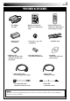
EN PROVIDED ACCESSORIES •AC Adapter AP-V10U •Remote Control Unit RM-V716U (GR-DVL817 only) •Battery Pack BN-V408U •Lens Cap ( pg. 6 for attachment) •Memory Card 8 MB (GR-DVL817 only) (Already inserted in the camcorder) •AAA (R03) Battery x 2 (for remote control unit) •Remote Control Unit RM-V715U (GR-DVL517/ DVL515/DVL317 only) •Shoulder Strap •CD-ROM (GR-DVL817/DVL517/ DVL515 only) •Audio/Video Cable (ø3.
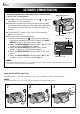
EN AUTOMATIC DEMONSTRATION Automatic Demonstration takes place when “DEMO MODE” is set to “ON” (factory-preset). Available when the Power Switch is set to “ ” or “ ” and no cassette is in the camcorder. Performing any operation during the demonstration stops the demonstration temporarily. If no operation is performed for more than 1 minute after that, the demonstration will resume. “DEMO MODE” remains “ON” even if the camcorder power is turned off. To cancel Automatic Demonstration: 1.
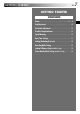
GETTING STARTED EN GETTING STARTED CONTENTS Power .................................................. 8 – 9 Grip Adjustment ......................................... 10 Viewfinder Adjustment .................................. 10 Shoulder Strap Attachment ............................. 10 Tripod Mounting .......................................... 10 Date/Time Settings...................................... 11 Loading/Unloading A Cassette ......................... 12 Recording Mode Setting ....................
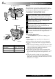
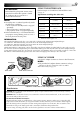
GETTING STARTED (cont.) EN BAT. RELEASE Switch Power This camcorder’s 2-way power supply system lets you choose the most appropriate source of power. Do not use provided power supply units with other equipment. CHARGING THE BATTERY PACK 1 2 3 Power Switch CHARGE Lamp 1 Tilt the viewfinder upward 1. With the arrow on the battery pack pointing downward, push the battery pack slightly against the battery pack mount 2, then slide down the battery pack until it locks in place 3.
EN 9 USING THE BATTERY PACK ATTENTION: Before detaching the power source, make sure that the camcorder’s power is turned off. Failure to do so can result in a camcorder malfunction. NOTES: ● Recording time is reduced significantly under the following conditions: • Zoom or Record-Standby mode is engaged repeatedly. • The LCD monitor is used repeatedly. • The playback mode is engaged repeatedly.
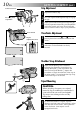
GETTING STARTED (cont.) EN Power Zoom Lever Grip Adjustment Recording Start/ Stop button 1 2 3 PAUSE Pass your right hand through the loop and grasp the grip. Adjust your thumb and fingers through the grip, to easily operate the Recording Start/Stop button and Power Switch and Power Zoom Lever. Be sure to fasten the Velcro strip to your preference.
EN MENU/BRIGHT Wheel Power Lamp Lock Button Power Switch Display W I PE / FADER PROGRAM AE W. BAL ANC E CAMERA MANUA L SYSTEM D I SPL AY DSC OF F GR-DVL817 only END ON SCRE E N DATE / T I ME T I ME CODE CLOCK ADJ . – LCD / TV – AU T O – OF F D E C 25 ’01 5 : 30 PM RETURN CLOCK ADJ . D E C 25 ’01 5 : 30 PM DISPLAY Menu 11 Date/Time Settings The date/time is recorded onto the tape at all times, but its display can be turned on or off during playback ( pg. 50, 51).
GETTING STARTED (cont.) EN Erase protection tab* Loading/Unloading A Cassette The camcorder needs to be powered up to load or eject a cassette. Make sure the window side is facing out. PUSH HERE Cassette holder Cassette holder cover OPEN/EJECT Switch * To Protect Valuable Recordings . . . .... slide the erase protection tab on the back of the tape in the direction of “SAVE”. This prevents the tape from being recorded over. To record on this tape, slide the tab back to “REC” before loading it.
EN MENU/BRIGHT Wheel Power Lamp Lock Button Power Switch Display REC MODE – SP LP Menu Screen Sub Menu GR-DVL817 only 13 Recording Mode Setting Set the tape recording mode depending on your preference. 1 Set the Power Switch to “ ” while pressing down the Lock Button located on the switch. The power lamp lights and the camcorder is turned on. 2 3 Press the MENU/BRIGHT wheel in. The Menu Screen appears. 4 Rotate the MENU/BRIGHT wheel to select “REC MODE” and press it. The Sub Menu appears.
GETTING STARTED (cont.) EN Clipped edge MENU/BRIGHT Wheel Memory card Label Power Lamp Display Card Cover – – – – QUAL I TY S I ZE UXGA Lock Button F I NE STANDARD VGA AUTO Power Switch RETURN Loading A Memory Card Picture Quality Mode Setting (GR-DVL817 only) (GR-DVL817 only) The provided memory card is already inserted in the camcorder when you receive the camcorder. The Picture Quality mode can be selected to best match your needs.
VIDEO RECORDING & PLAYBACK EN 15 VIDEO RECORDING & PLAYBACK CONTENTS VIDEO RECORDING ....................... 16 – 20 Basic Recording ...................................... 16 Journalistic Shooting ................................ 17 Self-Recording ....................................... 17 Operation Mode ..................................... 17 Zooming ............................................. 18 Video Light .......................................... 19 Time Code .....................................
VIDEO RECORDING EN Basic Recording Power lamp Power Switch NOTE: You should already have performed the procedures listed below. If not, do so before continuing. ● Power ( pg. 8) ● Grip Adjustment ( pg. 10) ● Viewfinder Adjustment ( pg. 10) ● Load A Cassette ( pg. 12) ● Recording Mode Setting ( pg. 13) During shooting Lock Button 1 Press in the tabs on the lens cap to remove it. GR-DVL817 only: Press PUSH OPEN, open the LCD monitor and set the VIDEO/DSC Switch to “VIDEO”.
EN 17 JOURNALISTIC SHOOTING In some situations, different shooting angles may provide more dramatic results. Hold the camcorder in the desired position and tilt the LCD monitor in the most convenient direction. It can rotate 270° (90° downward, 180° upward). Self-Recording SELF-RECORDING You can shoot yourself while viewing your own image in the LCD monitor. Open the LCD monitor and tilt it upward 180° so that it faces forward, then point the lens toward yourself and start recording.
VIDEO RECORDING (cont.) EN Zoom in (T: Telephoto) 1x W FEATURE: Zooming PURPOSE: T 10 x W T 20 x W T 40 x W T To produce the zoom in/out effect, or an instantaneous change in image magnification. OPERATION: Zoom out (W: Wide angle) Zoom display 10 x W T Digital zoom zone 10X (optical) zoom zone Approximate zoom ratio Power Zoom Lever Zoom In Slide the Power Zoom Lever towards “T”. Zoom Out Slide the Power Zoom Lever towards “W”.
EN 19 FEATURE: Video Light PURPOSE: To brighten the scene when natural lighting is too dim. OPERATION: LIGHT OFF/AUTO/ON Switch (Open the LCD monitor to access this switch.) DANGER The video light can become extremely hot. Do not touch it either while in operation or soon after turning it off, otherwise serious injury may result. Do not place the camcorder into the carrying case immediately after using the video light, since it remains extremely hot for some time.
VIDEO RECORDING (cont.) EN Time Code During recording, a time code is recorded on the tape. This code is to confirm the location of the recorded scene on the tape during playback. If recording starts from a blank portion, the time code begins counting from “00:00:00” (minute:second:frame). If recording starts from the end of a previously recorded scene, the time code continues from the last time code number. To perform Random Assemble Editing ( pg. 61 – 65), time code is necessary.
VIDEO PLAYBACK EN 21 Normal Playback Lock Button Power Switch Power Zoom Lever (VOL.) Play/Pause Button (4/6) Rewind Button (2) Stop Button (5) Fast-Forward Button (3) Speaker VIDEO/DSC Switch (GR-DVL817 only; open the LCD monitor to access this switch) 1 2 Load a tape ( pg. 12). Set the VIDEO/DSC Switch to “VIDEO” (GR-DVL817 only), then set the Power Switch to “ ” while pressing down the Lock Button located on the switch. To start playback, press 4/6. •To stop playback, press 5.
VIDEO PLAYBACK (cont.) EN Connections These are some basic types of connections. When making the connections, refer also to your VCR and TV instruction manuals. A. Connection to a TV or VCR equipped with an S-VIDEO IN and A/V input connectors Connector cover* S-Video cable (optional) To S To TV or VCR TV To S-VIDEO IN To AV Audio/Video cable (provided) NOTE: In order to maintain optimum performance of the camcorder, provided cables may be equipped with one or more core filter.
EN 1 2 Make sure all units are turned off. 3 4 5 Connect the VCR output to the TV input, referring to your VCR’s instruction manual. Connect the camcorder to a TV or VCR as shown in the illustration ( pg. 22). If using a VCR . . . go to step 3. If not . . . go to step 4. Turn on the camcorder, the VCR and the TV. Set the VCR to its AUX input mode, and set the TV to its VIDEO mode. To choose whether or not the following displays appear on the connected TV . . . •Date/Time ....
VIDEO PLAYBACK (cont.) EN BLANK SEARCH Button Blank Search Helps you find where you should start recording in the middle of a tape to avoid time code interruption ( pg. 20). Lock Button Power Switch Display 44 1 2 Load a tape ( pg. 12). 3 Press BLANK SEARCH. •“BLANK SEARCH” appears blinking and the camcorder automatically starts reverse or forward shuttle search, then stops at the spot which is about 3 seconds of tape before the beginning of the detected blank portion.
DIGITAL STILL CAMERA (D.S.C.) RECORDING & PLAYBACK EN 25 DIGITAL STILL CAMERA (D.S.C.) RECORDING & PLAYBACK The D.S.C. (Digital Still Camera) features are available on GR-DVL817. CONTENTS D.S.C. RECORDING ....................... 26 – 27 Basic Shooting (Snapshot) ................... 26 – 27 D.S.C. PLAYBACK ......................... 28 – 36 Normal Playback .................................... 28 Auto Playback ....................................... 28 INDEX Screen ........................................
D.S.C. RECORDING EN Basic Shooting (Snapshot) SNAPSHOT Button You can use your camcorder as a Digital Still Camera for taking snapshots. Lock Button Power Switch SNAPSHOT MODE SELECTION VIDEO/DSC Switch (Open the LCD monitor to access this switch.) Display Menu Screen SNAP MODE NOTE: You should already have performed the procedures listed below. If not, do so before continuing. ● Power ( pg. 8) ● Grip Adjustment ( pg. 10) ● Viewfinder Adjustment ( pg. 10) ● Loading A Memory Card ( pg.
EN PIN-UP Pin-Up mode* 27 To Delete Unwanted Still Images . . . .... when unwanted still images are stored in the memory card or its memory is full, refer to “Deleting Images” ( pg. 32) and delete unwanted still images. To Remove The Shutter Sound . . . .... when you do not want to hear the shutter sound, set “BEEP” to “OFF” in the Menu Screen ( pg. 46, 48). The sound is no longer heard from the speaker.
D.S.C. PLAYBACK EN Normal Playback Fast-Forward (3) Button Lock Button PL Play (4/6) Button OFF AY Rewind (2) Button Stop (5) Button Power Switch Images shot with the camcorder are automatically numbered, then stored in numerical order in the memory card. You can view the stored images, one at a time, much like flipping through a photo album. 1 2 3 VIDEO/DSC Switch (Open the LCD monitor to access this switch.
EN INDEX Screen Picture quality Index number Selected image EXIT 100-DVC00003 1 F 29 VGA 2 S 3 S The images you shot can be displayed together with their index information. Convenient for checking images shot beforehand, the INDEX Screen also shows the Picture quality as well as which images are protected against accidental erasure. 1: Index number 5 F 4 F 6 F Index numbers are marked from 1.
D.S.C. PLAYBACK (cont.) EN MENU/BRIGHT Wheel JUMP Button Jump Playback When viewing still images stored in a memory card, you can call up directly an image you want to view by specifying its index number. 1 2 Display Jump Screen JUMP MENU 10 / 50 S E L E C T / SET CANC E L Index number [ ME NU ] [ J UMP ] Total number of images Press JUMP during Normal Playback (墌 pg. 28). The Jump Screen appears. Rotate the MENU/BRIGHT wheel to enter the index number of the desired image and press it.
EN 31 Protecting Images MENU/BRIGHT Wheel The Protect mode helps prevent the accidental erasure of images. When a padlock mark is displayed next to the Picture Quality indication, that image cannot be deleted. Lock Button Power Switch 1 Set the VIDEO/DSC Switch to “ ”, then set the Power Switch to “ ” while pressing down the Lock Button. •A stored image is displayed. 2 Press the MENU/BRIGHT wheel in. The Menu Screen appears. Rotate the MENU/BRIGHT wheel to select “ MEMORY” and press it.
D.S.C. PLAYBACK (cont.) EN MENU/BRIGHT Wheel Deleting Images Previously shot images can be deleted either one at a time or all at once. Lock Button Power Switch 1 Set the VIDEO/DSC Switch to “ ”, then set the Power Switch to “ ” while pressing down the Lock Button. •A stored image is displayed. 2 Press the MENU/BRIGHT wheel in. The Menu Screen appears. Rotate the MENU/BRIGHT wheel to select “ MEMORY” and press it. The MEMORY Menu appears.
EN MENU/BRIGHT Wheel 33 TO DELETE ALL IMAGES Before doing the following, perform steps 1 through 3 on pg. 32. 4 5 Rotate the MENU/BRIGHT wheel to select “ALL” and press it. The Deletion Confirmation Screen appears. Rotate the MENU/BRIGHT wheel to select “EXECUTE” and press it. All the images are deleted. •To cancel deletion, rotate the MENU/BRIGHT wheel to select “CANCEL” and press it. NOTES: ● Protected images ( 墌 pg. 31) cannot be deleted with the above operation.
D.S.C. PLAYBACK (cont.) EN MENU/BRIGHT Wheel Setting Print Information (DPOF Setting) This camcorder is compatible with the DPOF (Digital Print Order Format) standard in order to support future systems such as automatic printing, which records information about the still images you wish to print (such as the number of prints to make). There are 2 print information settings available: “To print all still images (one print for each)” explained below and “To print by selecting still images and no.
MENU/BRIGHT Wheel Display 100-DVC00021 NEXT DPOF Screen VGA 19 00 20 00 21 03 22 00 23 00 24 00 DPOF SE L ECT – CANCEL EXECUTE Confirmation Screen EN TO PRINT BY SELECTING STILL IMAGES AND NO. OF PRINTS 1 2 Perform steps 1 through 3 on pg. 34. 3 4 Rotate the MENU/BRIGHT wheel to move the green frame to the image you wish to print and press it. Rotate the MENU/BRIGHT wheel to selsect “SELECT” and press it. Selection is complete. The DPOF Screen appears.
D.S.C. PLAYBACK (cont.) EN MENU/BRIGHT Wheel Initializing A Memory Card You can initialize a memory card anytime. After initializing, all images and data stored in the memory card, including those which have been protected, are cleared. Lock Button Power Switch VIDEO/DSC Switch (Open the LCD monitor to access this switch) 1 Set the VIDEO/DSC Switch to “ ”, then set the Power Switch to “ ” while pressing down the Lock Button. •A stored image is displayed. 2 Press the MENU/BRIGHT wheel in.
ADVANCED FEATURES EN 37 ADVANCED FEATURES CONTENTS FOR RECORDING ............................................ 38 – 45 Night-Alive ............................................................. 38 Program AE With Special Effects .............................. 38 – 39 Fade/Wipe Effects .............................................. 40 – 41 Snapshot (For Video Recording) ...................................... 42 Auto Focus/Manual Focus ............................................. 43 Exposure Control .......
FOR RECORDING EN NOTES: ● During Night-Alive, the following functions or settings cannot be activated and its indicator blinks or goes out: • Some modes of “Program AE With Special Effects” ( 墌 pg. 38, 39), “Picture Wipe/ Dissolve” ( 墌 pg. 40. 41). • “GAIN UP” in CAMERA MENU ( 墌 pg. 47). • “DIS” in MANUAL MENU ( 墌 pg. 47). • “Video light” when LIGHT OFF/AUTO/ON is set to “AUTO” ( 墌 pg. 19). ● During Night-Alive, it may be difficult to bring the camcorder into focus.
EN SHUTTER 1/60–The shutter speed is fixed at 1/60th of a second. Black bands that usually appear when shooting a TV screen become narrower. 1/100–The shutter speed is fixed at 1/100th of a second. The flickering that occurs when shooting under a fluorescent light or mercury-vapor lamp is reduced. SPORTS (Variable Shutter Speed: 1/250 – 1/4000) This setting allows fast-moving images to be captured one frame at a time, for vivid, stable slow-motion playback.
FOR RECORDING (cont.) EN Fade/Wipe Effects These effects let you make pro-style scene transitions. Use them to spice up the transition from one scene to the next. You can also vary transitions from scene to scene. IMPORTANT: Some Fade/Wipe Effects cannot be used with certain modes of Program AE with special effects ( 墌 pg. 38, 39). If an unusable Fade/ Wipe Effect is selected, its indicator blinks or goes out.
EN 41 Fader And Wipe Menu Menu FADER — WHITE FADER — BLACK FADER — B.W MOSAIC Effect Fade in or out with a white screen. Fade in or out with a black screen. Fade in to a color screen from a black and white screen, or fade out from color to black and white. Fade in or out with a full-screen mosaic effect. WIPE — CORNER Wipe in on a black screen from the upper right to the lower left corner, or wipe out from lower left to upper right, leaving a black screen.
FOR RECORDING (cont.) EN Snapshot (For Video Recording) SNAPSHOT Button This feature lets you record still images that look like photographs onto a tape. SNAPSHOT MODE SELECTION Lock Button Power Switch VIDEO/DSC Switch (GR-DVL817 only; open the LCD monitor to access this switch.
EN Focus detection zone While focusing on a further subject 43 While focusing on a nearer subject FEATURE: Auto Focus PURPOSE: The camcorder’s Full Range AF system offers continuous shooting ability from close-up (as close as approx. 5 cm (2") to the subject) to infinity. However, correct focus may not be obtainable in the situations listed below (in these cases use manual focusing): •When two subjects overlap in the same scene. •When illumination is low.
FOR RECORDING (cont.) EN Exposure Control Iris Lock Manual exposure adjustment is recommended in the following situations: • When shooting using reverse lighting or when the background is too bright. • When shooting on a reflective natural background such as at the beach or when skiing. • When the background is overly dark or the subject light. Press EXPOSURE. The exposure control indicator appear. Use this function in the following situations: • When shooting a moving subject.
EN 45 White Balance Adjustment Manual White Balance Operation A term that refers to the correctness of color reproduction under various lighting. If the white balance is correct, all other colors will be accurately reproduced. The white balance is usually adjusted automatically. However, more advanced camcorder operators control this function manually to achieve a more professional color/tint reproduction. Perform Manual White Balance when shooting under various types of lighting.
USING MENUS FOR DETAILED ADJUSTMENT EN For Recording Menu MENU/BRIGHT Wheel This camcorder is equipped with an easy-to-use, on-screen menu system that simplifies many of the more detailed camcorder settings (墌 pg. 47 – 49) . Lock Button Power Switch Display W I PE / FADER PROGRAM AE W. BAL ANC E CAMERA MANUA L SYSTEM D I SPL AY DSC OF F 1 2 3 Set the Power Switch to “ ” while pressing down the Lock Button located on the switch. 4 Function menu setting depends on the function.
EN 47 Menu Screen Explanations WIPE/FADER Refer to “Fade/Wipe Effects” (墌 pg. 40, 41). PROGRAM AE Refer to “Program AE With Special Effects” (墌 pg. 38, 39). W.BALANCE Refer to “White Balance Adjustment” and “Manual White Balance Operation” (墌 pg. 45). REC MODE Allows you to set the video recording mode (SP or LP) depending on your preference (墌 pg. 13). SOUND MODE 12 BIT Enables video recording of stereo sound on four separate channels, and is recommended for use when performing audio dubbing.
EN USING MENUS FOR Menu Screen Explanations (cont.) TELE MACRO OFF ON Usually the distance to a subject where the lens is in focus depends on the zoom magnification. Unless there is a distance more than 1m (3.3 ft.) to the subject, the lens is out of focus at the maximum telephoto setting. When set to “ON”, you can shoot a subject as large as possible at a distance of approx. 60 cm (2 ft.). •Depending on the zoom position, the lens may go out of focus.
EN OFF Automatic demonstration will not take place. ON Demonstrates certain functions such as Program AE with special effects, etc., and can be used to confirm how these functions operate. When “DEMO MODE” is set to “ON” and the Menu Screen is closed, demonstration starts. Performing any operation during the demonstration stops the demonstration temporarily. If no operation is performed for more than 1 minute after that, the demonstration will resume.
EN USING MENUS FOR DETAILED ADJUSTMENT (cont.) For Playback Menu MENU/BRIGHT Wheel The following procedure applies to all except Synchro Comp ( 墌 pg. 65). Power Switch Lock Button Recording Start/Stop Button 1 2 3 Display V I DEO SYSTEM D I SPL AY MEMOR Y 4 5 6 SOUND MODE 12B I T MODE SYNCHRO REC MODE COPY END SOUND MOD E 12B I T MOD E SYNCHRO REC MODE COPY S / AV I N P UT – – – – – – STEREO SOUND 1 O.
EN Menu Screen Explanations (cont.) 51 DISPLAY MEMORY DISPLAY SYSTEM ON SCREEN setting: SP 46 12B I T / SOUND1 100-0001 1 / 50 Each setting is linked with “ DISPLAY” or “ SYSTEM”, which appears when the Power Switch is set to “ ” (墌 pg. 48, 49). The parameters are the same as in the description on pg. 48, 49. For playback sound, tape speed and tape running during video playback. 墌 pg. 28 – 36 (GR-DVL817 only) For directory, file name, index number and total number during D.S.C.
DUBBING EN Dubbing To A VCR 1 2 Connector cover* Power Switch To AV To S S-Video cable (optional) Audio/Video cable (provided) White to AUDIO L IN Yellow to VIDEO** IN To S-VIDEO IN Red to AUDIO R IN Following the illustration, connect the camcorder and the VCR. Also refer to pg. 22 and 23.
EN VIDEO/DSC Switch (GR-DVL817 only) 53 Dubbing To Or From A Video Unit Equipped With A DV Connector (Digital Dubbing) It is also possible to copy recorded scenes from the camcorder onto another video unit equipped with a DV connector. Since a digital signal is sent, there is little if any image or sound deterioration. [To use this camcorder as a player] To DV IN/OUT Lock Button PL Core filter DV cable (optional) OFF AY Make sure all units are turned off.
DUBBING (cont.) EN SNAPSHOT Button Dubbing Images Stored In A Memory Card To A Tape (GR-DVL817 only) Images can be dubbed from a memory card to a tape. 1 2 Load a memory card (墌 pg. 14) and cassette (墌 pg. 12). 3 Set the VIDEO/DSC Switch to “ ”, then set the Power Switch to “ ” while pressing down the Lock Button located on the switch. 4 To select a still image to be dubbed, perform Index Playback (墌 pg. 29), Auto Playback (墌 pg. 28) or press 2 or 3 to select the image you wish.
EN SNAPSHOT Button 55 Dubbing Images Recorded On A Tape To A Memory Card (GR-DVL817 only) Images can be dubbed from a tape to a memory card . Lock Button Power Switch Display Menu Screen COPY – OF F ON SP 6 Play/Pause Button (4/6) MENU/ BRIGHT Wheel VIDEO/DSC Switch (Open the LCD monitor to access this switch.) 1 2 Load a memory card (墌 pg. 14) and cassette (墌 pg. 12). 3 Set the VIDEO/DSC Switch to “VIDEO”, then set the Power Switch to “ ” while pressing down the Lock Button.
USING THE REMOTE CONTROL UNIT EN 1 3 RM-V716U 2 Tab – + – – + – + Installing The Batteries (RM-V716U or RM-V715U, provided) 1 3 The Full-Function Remote Control Unit can operate this camcorder from a distance as well as the basic operations (Playback, Stop, Pause, Fast-Forward and Rewind) of your VCR. It also makes additional playback functions possible. For GR-DVL517/DVL515/DVL317 Owners: If you want to perform Random Assemble Editing (墌 pgs.
EN 1 0 2 4 57 ! 3 5 @ # $ % ^ & * ( ) 6 7 8 9 RM-V716U (Provided with GR-DVL817 only) Functions Buttons With the camcorder’s Power Switch set to the camera position (“ ” or “ ”) . 1 Infrared beam transmitting window Transmits the beam signal. 2 Zoom (T/W) Buttons Zoom in/out (墌 pg. 18) 3 DISPLAY Button — 4 SHIFT Button — 5 SLOW Rewind/Forward Buttons — — Left/Right Buttons With the camcorder’s Power Switch set to “ ”. Zoom in/out (墌 pg. 60) 墌 pg. 23, 52, 62 墌 pg. 60, 61 墌 pg. 59 墌 pg.
USING THE REMOTE CONTROL UNIT (cont.) EN 1 1 # 2 8 $ 8 4 5 7 2 9 7 ! 9 4 0 3 0 6 % @ 3 @ ^ 5 ! 6 & RM-V715U (Provided with GR-DVL517/ DVL515/DVL317 only) RM-V700U (optional) Functions Buttons With the camcorder’s Power Switch set to the camera position (“ ” or “ ”) . 1 Infrared beam Transmits the beam signal. With the camcorder’s Power Switch set ”. to “ transmitting window 2 ZOOM (T/W) Buttons Zoom in/out (墌 pg. 18) Zoom in/out (墌 pg.
EN Remote sensor 59 FEATURE: Slow-Motion Playback (GR-DVL817 only) PURPOSE: To allow slow-speed search in either direction during video playback. OPERATION: 1) To change from normal to Slow-Motion Playback, press SLOW (9 or 0) more than approx. 2 seconds. After approx. 1 minute in Slow Rewind or approx. 2 minutes in Slow Forward, normal playback resumes. 䡲 To stop Slow-Motion Playback, press PLAY (4).
USING THE REMOTE CONTROL UNIT (cont.) EN Remote sensor FEATURE: Playback Zoom PURPOSE: To magnify the recorded image up to 40X at any time during playback. OPERATION: 1) Press PLAY (4) to find the scene of interest. 2) Press the Zoom Buttons (T/W) on the remote control. Make sure the remote control is pointed at the camcorder's remote sensor. Pressing T zooms in. 3) For GR-DVL817 Owners: You can move the image on screen around to find a particular portion of the picture.
EN 61 Random Assemble Editing [R.A.Edit] Create edited videos easily using your camcorder as the source player. You can select up to 8 “cuts” for automatic editing, in any order you like. R.A.Edit is more easily performed when the MBR (Multi-Brand Remote) is set to operate with your brand of VCR (see VCR CODE LIST), but can also be performed by operating the VCR manually. For GR-DVL517/DVL515/DVL317 Owners: Use the optional RM-V700U remote control.
USING THE REMOTE CONTROL UNIT (cont.) EN MAKE CONNECTIONS Connector cover** Also refer to pg. 22 and 23. 1 To S To AV ... connect the editing cable to the Remote PAUSE connector. A JVC VCR not equipped with a remote pause connector but equipped with an R.A. EDIT connector . . . To JLIP*** or EDIT*** Audio/Video cable (provided) ... connect the editing cable to the R.A.EDIT connector.
EN 63 SELECT SCENES Program IN 1–– –– : –– 2 3 4 5 6 7 8 T I ME CODE TOTAL MODE OUT ~ ~ ~ ~ ~ ~ ~ ~ Random Assemble Editing Menu –– : –– 0 0 : 00 4 Point the remote control at the camcorder’s remote sensor. Press PLAY (4) and then press R.A.EDIT ON/ OFF or ON/OFF on the remote control. The Random Assemble Editing Menu appears. 5 For GR-DVL817 Owners: If using a Fade/Wipe at the beginning of the scene, press FADE/WIPE on the remote control.
USING THE REMOTE CONTROL UNIT (cont.) EN AUTOMATIC EDITING TO VCR Recording Start/Stop Button IN 00 : 2 5 1 2 07 : 18 3 – – 0 3 : 33 09 : 30 4 5 15 : 55 6–– –– : –– 7 8 T I ME CODE TOTAL ~ ~ ~ ~ ~ ~ ~ ~ OUT MODE 02 : 05 –– 08 : 31 – – – – 05 : 53 13 : 15 16 : 29 – – – – 11 12 Rewind the tape in the camcorder to the beginning of the scene you want to edit and press PAUSE (6). 13 Press the Recording Start/Stop Button on the camcorder.
EN For More Accurate Editing Program 1 IN 1–– –– : –– 2 3 4 5 6 7 8 T I ME CODE TOTAL MODE OUT ~ ~ ~ ~ ~ ~ ~ ~ Random Assemble Editing Menu –– : –– 0 0 : 00 – Some VCRs make the transition from Record-Pause to Record mode faster than others. Even if you begin editing for the camcorder and the VCR at exactly the same time, you may lose scenes you wanted, or find that you have recorded scenes you did not want. For a cleanly edited tape, confirm and adjust the timing of the camcorder against your VCR.
USING THE REMOTE CONTROL UNIT (cont.) EN Audio Dubbing Display 6e Audio Dub Standby mode The audio track can be customized only when recorded in the 12-bit mode ( pg. 47). NOTES: ● Audio Dubbing is not possible on a tape recorded in 16-bit audio, on a tape recorded in the LP mode or on a blank portion of a tape. ● To perform Audio Dubbing while watching on the television, make connections ( pg. 22).
EN 67 Insert Editing (GR-DVL817 only) You can record a new scene into a previously recorded tape, replacing a section of the original recording with minimal picture distortion at the in and outpoints. The original audio remains unchanged. Lock Button Power Switch Display 6w 12 : 34 Remote sensor START/STOP REW INSERT PLAY STOP PAUSE NOTES: ● Before performing the following steps, make sure that “TIME CODE” is set to “ON” in the Menu Screen ( pg. 50).
SYSTEM CONNECTIONS EN [A]Using USB or PC connection cable GR-DVL517/DVL515/DVL317 only To PC (DIGITAL PHOTO) PC connection cable (provided with GR-DVL517/ To RS-232C DVL515 only) USB cable (provided) To USB To USB connector PC GR-DVL817 only [B] Using DV cable Power Switch OR Core filter To DV IN/OUT Core filter DV cable (optional) To DV connector PC with DV connector VIDEO/DSC Switch (GR-DVL817 only; open the LCD monitor to access this switch.
EN 69 Connection To A Video Unit Equipped With A DV Connector Power Switch To DV IN/OUT Core filter DV cable (optional) Core filter To DV IN connector To DV connector Video unit equipped with a DV connector To PC connector Digital Printer PC connection cable To RS-232C PC Connection to the GV-DT3 Digital Printer (optional) allows you to print out images or transfer them to a PC. It is also possible to copy recorded scenes from the camcorder onto another video unit equipped with a DV connector.
EN REFERENCES REFERENCES CONTENTS DETAILS ............................................. 71 TROUBLESHOOTING ........................ 72 – 76 USER MAINTENANCE .............................. 77 INDEX ........................................ 78 – 84 Controls, Connectors And Indicators ........ 78 – 79 Indications .................................... 80 – 84 CAUTIONS ................................... 85 – 87 TERMS ....................................... 88 – 89 SPECIFICATIONS ............................
DETAILS ITEMS EN 71 NOTES ➪ Power ( pg. 8) ❍ Perform charging where the temperature is between 10°C and 35°C (50°F and 95°F). 20°C to 25°C (68°F to 77°F) is the ideal temperature range for charging. If the environment is too cold, charging may be incomplete. ❍ Charging times are for a fully discharged battery pack. ❍ Charging time varies according to the ambient temperature and the status of the battery pack. ❍ To avoid interference with reception, do not use the AC Adapter near a radio.
TROUBLESHOOTING EN If, after following the steps in the chart below, the problem still exists, please consult your nearest JVC dealer. The camcorder is a microcomputer-controlled device. External noise and interference (from a TV, a radio, etc.) might prevent it from functioning properly. In such cases, first disconnect its power supply unit (battery pack, AC Adapter, etc.) and wait a few minutes; and then re-connect it and proceed as usual from the beginning.
EN 73 SYMPTOM POSSIBLE CAUSES CORRECTIVE ACTION 9. The color of Snapshot looks strange. 9. • The light source or the subject does not include white. Or there are various different light sources behind the subject. • The Sepia or Monotone mode is activated. 9. • Find a white subject and compose your shot so that it also appears in the frame ( pg. 26, 42). • Turn off Sepia and Monotone ( pg. 38, 39). 10. The image taken using Snapshot is too dark. 10.
EN SYMPTOM TROUBLESHOOTING (cont.) POSSIBLE CAUSES CORRECTIVE ACTION 16. The picture wipe function does not work. 16. • The Slow Shutter mode is activated. • “WIDE MODE” is not set to “OFF”. 16. • Disengage the Slow Shutter mode or set “WIDE MODE” to “OFF” before preparing to use the Picture Wipe ( pg. 38, 40, 48). 17. Scene transition does not go as expected. 17. • When using “Picture Wipe/ Dissolve” ( pg.
EN 75 SYMPTOM POSSIBLE CAUSES CORRECTIVE ACTION 26. The indicators and messages do not appear. 26. • “TIME CODE” is set to “OFF” in the Menu Screen. 26. • Set “TIME CODE” to “ON” in the Menu Screen ( pg. 49, 50). 27. Images on the LCD monitor appear dark or whitish. 27. • In places subject to low temperature, images become dark due to the characteristics of the LCD monitor. When this happens, the displayed colors differ from those that are actually recorded. This is not a defect of the camcorder.
TROUBLESHOOTING (cont.) EN SYMPTOM 35. The LCD monitor image is distorted. POSSIBLE CAUSES CORRECTIVE ACTION 35. • During playback of the unrecorded portion, Highspeed Search and still playback, LCD monitor indications appear distorted. This is not a defect. 35. 36. Images on the LCD monitor are jittery. 36. • The speaker volume is too great. 36. • Turn the speaker volume down ( pg. 21). 37. Blocks of noise appear during playback, or there is no playback picture and the screen becomes blue.
USER MAINTENANCE EN 77 After Use Cleaning The Camcorder 1 2 1 To clean the exterior, wipe gently with a soft cloth. Put the cloth in diluted mild soap and wring it well to wipe off heavy dirt. Then wipe again with a dry cloth. 2 Press PUSH-OPEN and open the LCD monitor. Wipe gently with a soft cloth. Be careful not to damage the monitor. Close the LCD monitor. 3 4 To clean the lens, blow it with a blower brush, then wipe gently with lens cleaning paper.
INDEX Controls, Connectors And Indicators EN y r o * ( ) q 1 t p Q 2 345 67 i u PLAY O 78 FF @# $ R E W 890! I O P & Y U T e w %^
EN Controls 1 Monitor Open Button [PUSH OPEN] ..................................... pg. 16 2 Diopter Adjustment Control ................. pg. 10 3 Battery Release Switch [BAT. RELEASE] ...................................... pg. 8 4 •MENU Wheel [+, –, PUSH] ............... pg. 46 5 6 7 8 9 0 ! @ # $ % ^ & •LCD Monitor BRIGHT (Brightness) Control [+, –] .................. pg. 16 Snapshot Button [SNAPSHOT] ................ pg. 26, 27, 42, 54, 55 •Power Zoom Lever [T/W] ..................
INDEX Indications EN LCD Monitor/Viewfinder Indications During Video Recording Only 1 2 1 3 4 5 LP 50 min P REC 6w 6 2 3 4 5 6 7 SOUND 1 2 B I T 8 20 : 5 5 9 0 9 8 7 0 Displays the selected Fade/Wipe effect. ( pg. 40, 41) Appears when in the Squeeze or Cinema mode. ( pg. 48) Rotates while the tape is running. ( pg. 16) Displays the recording mode (SP or LP). ( pg. 13) Displays the tape remaining time. ( pg. 16) • “REC” appears during recording.
EN 81 LCD Monitor/Viewfinder Indications During Both Video And D.S.C. Recording 8 9 1 40 x W T 2 4 PHOTO 3 5 6 3 BR I GHT JAN 1 0 ’ 0 1 1 0 : 0 0 AM 7 # 1 2 3 4 5 0 Appears when the Power Switch is set to “ ”. ( pg. 17) • : Appears when Night-Alive is engaged. ( pg. 38) • : Appears when “GAIN UP” is set to “AUTO” and the shutter speed is being automatically adjusted. ( pg. 47) Appears when the white balance is adjusted. ( pg. 45) • “±”: Appears when the exposure is adjusted. ( pg.
INDEX Indications (cont.) EN LCD Monitor/Viewfinder Indications During Video Playback 1 2 3 4 1 2B I T / SOUND 1 L 1 2 3 4 S P 64 B L ANK SEARCH VO L UME DEC 2 5 ’ 0 1 1 0 : 0 0 AM 20 : 21 : 25 6 7 5 6 5 7 Displays the sound mode. ( pg. 50, 51) Displays the Blank Search mode. ( pg. 24) Displays the tape speed. ( pg. 13) Appears while a tape is running.
EN 83 Warning Indications Indications Function Displays the battery remaining power. Remaining power level: high Remaining power level: exhausted As the battery power comes close to nil, the battery indicator blinks. When the battery power is exhausted, power turns off automatically. ( pg. 12) Appears when no tape is loaded.
EN Indications INSERT ERROR! INSERT ERROR! INDEX Indications (cont.) Function Appears if Insert Editing is attempted on a blank portion of a tape. ( pg. 67) ● Appears if Insert Editing is attempted on a tape recorded in the LP mode. ( pg. 67) ● Appears if INSERT (w) on the remote control is pressed when the erase protection tab is set to “SAVE”. ( pg.
CAUTIONS When using the AC Adapter in areas other than the USA The provided AC Adapter features automatic voltage selection in the AC range from 110 V to 240 V. USING HOUSEHOLD AC PLUG ADAPTER In case of connecting the unit’s power cord to an AC wall outlet other than American National Standard C73 series type use an AC plug adapter, called a “Siemens Plug”, as shown. For this AC plug adapter, consult your nearest JVC dealer. Plug adapter Video Light DANGER The video light can become extremely hot.
EN 2. Store cassettes . . . ... away from heaters or other heat sources. ... out of direct sunlight. ... where they won’t be subject to unnecessary shock or vibration. ... where they won’t be exposed to strong magnetic fields (such as those generated by motors, transformers or magnets). ... vertically, in their original cases. Memory Cards To properly use and store your memory cards, be sure to read the following cautions: 1. During use . . . ...
EN How To Handle A CD-ROM •Take care not to soil or scratch the mirror surface (opposite to the printed surface). Do not write anything or put a sticker on either the front or back surface. If the CD-ROM gets dirty, gently wipe it with a soft cloth outward from the center hole using a circular motion. •Do not use conventional disc cleaners or cleaning spray. •Do not bend the CD-ROM or touch its mirror surface. •Do not store your CD-ROM in a dusty, hot or humid environment.
TERMS EN A F AC Adapter ............................................ pg. 8, 9 Audio Dubbing ........................................ pg. 66 Auto Date ................................................. pg. 49 Auto Focus ............................................... pg. 43 Auto Playback .......................................... pg. 28 Auto Shut off ................................ pg. 16, 21, 27 Fade-In/Out ........................................ pg. 40, 41 Fast-Forward The Tape ....
EN 89 P T Picture Quality Mode ............................... pg. 14 Picture Wipe/Dissolve ......................... pg. 40, 41 Playback Special Effects ............................ pg. 59 Playback Zoom ........................................ pg. 60 Power Switch Position .............................. pg. 17 Printer ...................................................... pg. 69 Program AE With Special Effects .......... pg. 38, 39 Protecting Images .....................................
SPECIFICATIONS EN Camcorder For General Power supply : DC 11.0 V DC 7.2 V Power consumption LCD monitor off, viewfinder on LCD monitor on, viewfinder off Video light Dimensions (W x H x D) : : : : Weight : Operating temperature Operating humidity Storage temperature Pickup Lens Filter diameter LCD monitor : : : : : : : Viewfinder : Speaker : (Using AC Adapter) (Using battery pack) Approx. 4.3 W Approx. 5.3 W Approx. 3.
EN 91 For Digital Still Camera (GR-DVL817 only) Storage media : Compression system : File size : Picture quality : Approximate number of storable images with memory card [8 MB] (provided) FINE : STANDARD : with memory card [16 MB] (optional) FINE : STANDARD : with memory card [32 MB] (optional) FINE : STANDARD : with memory card [64 MB] (optional) FINE : STANDARD : SD Memory Card/MultiMediaCard JPEG (compatible) VGA (640 x 480 pixels) 2 modes (FINE/STANDARD) 100 200 200 400 400 800 800 1600 For Connect
EN GR-DVL817 GR-DVL517 GR-DVL515 GR-DVL317 VICTOR COMPANY OF JAPAN, LIMITED COPYRIGHT© 2000 VICTOR COMPANY OF JAPAN, LTD.