ENGLISH CONTENTS AUTOMATIC DEMONSTRATION 7 GETTING STARTED 8 – 15 RECORDING DIGITAL VIDEO CAMERA GR-DVM80 Please visit our Homepage on the World Wide Web and answer our Consumer Survey (in English only): http://www.jvc-victor.co.jp/english/index-e.html 16– 35 Basic Recording .............................. 16 Advanced Features .......................... 22 PLAYBACK 36 – 43 Basic Playback ............................... 36 Advanced Features .......................... 37 Basic Connections .............
EN Dear Customer, Thank you for purchasing this digital video camera. Before use, please read the safety information and precautions contained in the following pages to ensure safe use of this product. Using This Instruction Manual • All major sections and subsections are listed in the Table Of Contents on the cover page. • Notes appear after most subsections. Be sure to read these as well. • Basic and advanced features/operation are separated for easier reference. It is recommended that you . . . ...
EN IMPORTANT PRODUCT SAFETY INSTRUCTIONS Electrical energy can perform many useful functions. But improper use can result in potential electrical shock or fire hazards. This product has been engineered and manufactured to assure your personal safety. In order not to defeat the built-in safeguards, observe the following basic rules for its installation, use and servicing. ATTENTION: Follow and obey all warnings and instructions marked on your product and its operating instructions.
EN USE SERVICING 1. Accessories 1. Servicing To avoid personal injury: •Do not place this product on an unstable cart, stand, tripod, bracket or table. It may fall, causing serious injury to a child or adult, and serious damage to the product. •Use only with a cart, stand, tripod, bracket, or table recommended by the manufacturer or sold with the product. •Use a mounting accessory recommended by the manufacturer and follow the manufacturer’s instructions for any mounting of the product.
EN 5 SAFETY PRECAUTIONS Do not point the lens or the viewfinder directly into the sun. This can cause eye injuries, as well as lead to the malfunctioning of internal circuitry. There is also a risk of fire or electric shock. CAUTION! The following notes concern possible physical damage to the camcorder and to the user. When carrying, be sure to always securely attach and use the provided shoulder strap.
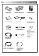
PROVIDED ACCESSORIES EN •Docking Station CU-V503U •AC Power Adapter/Charger AA-V51U •Remote Control Unit RM-V716U •Battery Pack BN-V507U •DC Cord •AAA (R03) Battery x 2 (for remote control unit) •Cleaning Cloth •JLIP Cable (Both plugs have 3 rings around the pin.) •CD-ROM The CD ROM contains the following 5 software programs: •Audio/Video Cable (ø3.5 mini-plug to RCA plug) •Editing Cable (One plug has 3 rings around the pin, and the other has 1 ring around the pin.
EN How To Use Audio Cables When using an optional external microphone or headphones, connect to the provided Audio cable (with a core filter attached), then connect the Audio cable to the camcorder. The core filter reduces interference. Microphone Headphones To AV OUT Core Filter Audio cable Core Filter To MIC AUTOMATIC DEMONSTRATION Automatic Demonstration takes place when “DEMO. MODE” is set to “ON” (factory-preset).
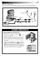
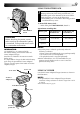
GETTING STARTED EN CHARGE indicator POWER indicator Battery pack BN-V507U or BN-V514U Power To AC outlet This camcorder’s 2-way power supply system lets you choose the most appropriate source of power. Do not use provided power supply units with other equipment. CHARGING THE BATTERY PACK 1 Make sure you unplug the camcorder’s DC cord from the AC Power Adapter/Charger. Plug the AC Adapter/ Charger’s power cord into an AC outlet. The POWER indicator lights.
EN 9 USING THE BATTERY PACK 1 1 Insert the terminal end 1 of the battery pack into the battery pack mount, then firmly push the end 2 of the battery pack in the direction of the arrow until it locks into place as shown in the illustration. •If the battery pack is attached in the wrong position, a malfunction may occur. To Detach The Battery Pack. . . .... while sliding down BATT. RELEASE, detach it. Approximate recording time 2 BATT.
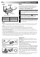
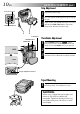
GETTING STARTED (cont.) EN Grip Adjustment Power Zoom Lever 1 2 3 START/STOP Button Lock Button POWER Switch MODE Dial Separate the Velcro strip. Pass your right hand through the loop and grasp the grip. Adjust so that your thumb and fingers can easily operate the START/STOP Button and Power Zoom Lever. Refasten the Velcro strip. Viewfinder Adjustment 1 Set the POWER Switch to “ ” while pressing down the Lock Button located on the switch and set the MODE Dial to any position.
EN Date/Time Settings POWER Switch POWER Lamp Lock Button The date/time is recorded onto the tape at all times, but its display can be turned on or off during playback ( pg. 37). 1 Set the Operation Switch to “ ” and set the POWER Switch to “ ” while pressing down the Lock Button located on the switch, then open the LCD monitor fully or pull out the viewfinder fully. The POWER lamp lights and the camcorder is turned on. 2 3 4 Press the MENU wheel. The Menu Screen appears.
GETTING STARTED (cont.) EN Cassette holder cover Cassette holder Make sure the window side is facing out. Loading/Unloading A Cassette The camcorder needs to be powered up to load or eject a cassette. 1 Slide down and hold OPEN/EJECT in the direction of the arrow then pull the cassette holder cover open until it locks. The cassette holder opens automatically. •Do not touch internal components. 2 Insert or remove a tape and press “PUSH HERE” to close the cassette holder.
EN Recording Mode Setting POWER Switch POWER Lamp Lock Button Operation Switch MENU Wheel Display CAME RA ME NU 1R E T URN R E C MOD E SP SOUND MOD E L P Z OOM S NA P MOD E GA I N U P BE E P / T A L L Y I D NUMB E R D EMO . MOD E 13 Menu Screen Sub Menu Set the tape recording mode depending on your preference.
GETTING STARTED (cont.) EN To turn on the camcorder, set the POWER Switch to any operation mode except “OFF” while pressing down the Lock Button located on the switch. POWER Switch Choose the appropriate operation mode according to your preference using the POWER Switch, Operation Switch and MODE Dial. POWER Switch Position POWER Lamp Lock Button Operation Switch When the Operation Switch is set to “ ”, “F. AUTO” appears. When set to “ ”, there is no indication. F .
EN MODE Dial MODE MODE Dial Position VIDEO PS V O IDE (Progressive mode) The following indications appear in the upper left corner, depending on the MODE Dial position. PS No display : When set to “VIDEO” PS : When set to “ ” 15 Function •Allows you to record video and still images. Approx. 6 seconds of a still image is inserted between video recordings ( pg. 18). •Zoom magnification over 10X is available ( pg. 19, 25).
RECORDING Basic Recording EN POWER Switch POWER Lamp Lock Button MODE Dial NOTE: You should already have performed the procedures listed below. If not, do so before continuing. ● Power ( pg. 8) ● Grip Adjustment ( pg. 10) ● Viewfinder Adjustment ( pg. 10) ● Load A Cassette ( pg. 12) ● Recording Mode Setting ( pg. 13) 1 START/STOP Button Display 25 min 90 min Tape remaining time indicator (Approximate) 89 min •The POWER lamp lights and the camcorder enters the Record-Standby mode.
EN 17 NOTES: ● When you use the LCD monitor outdoors in direct sunlight, the LCD monitor may be difficult to see. If this happens, use the viewfinder instead. ● The image will not appear simultaneously in the LCD monitor and the viewfinder. ● The cassette holder cannot be opened unless a power supply is attached. ● There may be a delay after you open the cassette holder cover until the cassette holder opens. Do not use force. ● Once the cassette holder is closed, it recedes automatically.
RECORDING Basic Recording (cont.) EN Snapshot MENU Wheel MODE Dial POWER Switch This feature lets you record still images that look like photographs onto a tape. SNAPSHOT MODE SELECTION Lock Button 1 Set the POWER Switch to “ ” while pressing down the Lock Button located on the switch and the MODE Dial to “VIDEO” or “ ”, then set the Operation Switch to “ ”. Pull out the viewfinder fully or open the LCD monitor fully. 2 3 4 5 Press the MENU wheel. The Menu Screen appears.
EN Zoom in (T: Telephoto) 1 xW FEATURE: Zooming PURPOSE: T 1 0 xW 19 T 20xW T 40xW T To produce the zoom in/out effect, or an instantaneous change in image magnification. OPERATION: Zoom out (W: Wide angle) Zoom display 10x W T Digital zoom zone 10X (optical) zoom zone Approximate zoom ratio POWER Switch Power Zoom Lever Zoom In Slide the Power Zoom Lever towards “T”. Zoom Out Slide the Power Zoom Lever towards “W”. The further you slide the Power Zoom Lever, the quicker the zoom action.
RECORDING Basic Recording (cont.) EN NOTE: Recording From The Middle Of A Tape Time Code During recording, a time code is recorded on the tape. This code is to confirm the location of the recorded scene on the tape during playback. If recording starts from a blank portion, the time code begins counting from “00:00:00” (minute:second:frame). If recording starts from the end of a previously recorded scene, the time code continues from the last time code number. To perform Random Assemble Editing ( pg.
EN Focus detection zone While focusing on a further subject While focusing on a nearer subject FOCUS FOCUS 21 FEATURE: Auto Focus PURPOSE: The camcorder’s Full Range AF system offers continuous shooting ability from close-up (as close as approx. 5 cm (2") to the subject) to infinity. However, correct focus may not be obtainable in the situations listed below (in these cases use manual focusing): •When two subjects overlap in the same scene. •When illumination is low.
RECORDING Advanced Features EN Progressive Mode Recording START/STOP Button MODE Dial POWER Switch Lock Button SNAPSHOT Button This mode lets you record moving images (successive jitter-free still images) onto a tape. Images can then played back jitter-free, with superior quality. High-resolution still images can also be processed on a personal computer or can be printed out ( pg. 43).
EN 23 Description of Progressive Scan CCD Progressive Scan is a special image sensing method which, unlike conventional interlace scanning, is able to pick up all the lines of picture information in one Scan. Since the Progressive Scan CCD is capable of outputting 60 full Frames* per second — twice the amount of conventional systems — it is able to deliver a high quality picture even when its output signal is converted to a format that can be viewed on a TV screen.
RECORDING Advanced Features (cont.) EN POWER Switch Lock Button Operation Switch MENU Wheel Display FAD E R / W I P E 4 Menu Screen W I P E – S CRO L L W I P E – S HU T T E R RANDOM OF F F AD E R –WH I T E F AD E R – B L ACK F AD E R – B . W CAME RA ME NU 1R E T URN R E C MOD E SP SOUND MOD E L P Z OOM S NA P MOD E GA I N U P BE E P / T A L L Y I D NUMB E R D EMO .
EN 25 Menu Screen Explanations FADER/WIPE Refer to “Fade/Wipe Effects” ( pg. 30, 31). P.AE/EFFECT Refer to “Program AE With Special Effects” ( pg. 32, 33). W.BALANCE Refer to “White Balance Adjustment” and “Manual White Balance Operation” ( pg. 35). REC MODE Allows you to set the recording mode (SP or LP) depending on your preference ( pg. 13). SOUND MODE 12 BIT Enables recording of stereo sound on four separate channels, and is recommended for use when performing audio dubbing.
CAMERA MENU EN Menu Screen Explanations (cont.) DEMO. MODE DIS ON Demonstrates certain functions such as Program AE with special effects, etc., and can be used to confirm how these functions operate. When “DEMO. MODE” is set to “ON” and the Menu Screen is closed, demonstration starts. Performing any operation during the demonstration stops the demonstration temporarily. If no operation is performed for more than 1 minute after that, the demonstration will resume.
MANUAL MENU EN WIND CUT DISPLAY MENU ON SCREEN DATE/ TIME TIME CODE CLOCK ADJ. 27 OFF Disengages the function which cuts down on noise created by wind. ON Helps cut down on noise created by wind. “ sound will change. This is normal. LCD Keeps the camcorder’s display (except the date, time and time code) from appearing on the connected TV screen. LCD/TV Makes the camcorder’s display appear on screen when the camcorder is connected to a TV.
RECORDING Advanced Features (cont.) EN Self-Timer START/STOP Button POWER Switch Lock Button Once the camcorder is set, the camcorder operator can become part of the scene in a more natural way, adding the final touch to a memorable picture. 1 Set the Operation Switch to “ ” and set the POWER Switch to “ ” while pressing down the Lock Button located on the switch, then pull out the viewfinder or open the LCD monitor fully.
EN 5-Second Recording START/STOP Button MODE Dial POWER Switch Lock Button Record a vacation or an important event in 5-second clips to keep the action moving. This function is available only for video recording. 1 Set the POWER Switch to “ ” while pressing down the Lock Button located on the switch and set the MODE Dial to “VIDEO” or “ ”, then set the Operation Switch to “ ”. Pull out the viewfinder fully or open the LCD monitor fully. 2 3 4 5 6 Press the MENU wheel. The Menu Screen appears.
RECORDING Advanced Features (cont.) EN Fade/Wipe Effects These effects let you make pro-style scene transitions. Use them to spice up the transition from one scene to the next. You can also vary transitions from scene to scene. IMPORTANT: Some Fade/Wipe Effects cannot be used with certain modes of Program AE with special effects ( pg. 32). If an unusable Fade/Wipe Effect is selected, its indicator blinks or goes out.
EN 31 Fader And Wipe Menu Menu FADER — WHITE FADER — BLACK Effect Fade in or out with a white screen. Fade in or out with a black screen. FADER — B.W Fade in to a color screen from a black and white screen, or fade out from color to black and white. WIPE — CORNER Wipe in on a black screen from the upper right to the lower left corner, or wipe out from lower left to upper right, leaving a black screen.
RECORDING Advanced Features (cont.) EN IMPORTANT: Some modes of Program AE with special effects cannot be used with certain Fade/Wipe Effects ( pg. 31). If an unusable mode is selected, its indicator blinks or goes out. MODE Dial POWER Switch Lock Button Operation Switch Program AE With Special Effects 1 Set the Operation Switch to “ ”, then set the POWER Switch to “ ” while pressing down the Lock Button located on the switch. Pull out the viewfinder fully or open the LCD monitor fully.
EN VIDEO ECHO* TWILIGHT Makes evening scenes look more natural. , but White Balance ( pg. 35) is initially set to can be changed to your desired setting. When Twilight is chosen, the camcorder automatically adjusts the focus from approx. 10 m (32 ft) to infinity. From less than 10 m (32 ft), adjust the focus manually. Adds a “ghost” to the subject, giving your recording a “fantasy” feeling. Zoom magnification of over 10X is not available. SEPIA Recorded scenes have a brownish tint like old photos.
EN RECORDING Advanced Features (cont.) Exposure Control Iris Lock Manual exposure adjustment is recommended in the following situations: • When shooting using reverse lighting or when the background is too bright. • When shooting on a reflective natural background such as at the beach or when skiing. • When the background is overly dark or the subject light. Use this function in the following situations: • When shooting a moving subject.
EN 35 White Balance Adjustment Manual White Balance Operation A term that refers to the correctness of color reproduction under various lighting. If the white balance is correct, all other colors will be accurately reproduced. The white balance is usually adjusted automatically. However, more advanced camcorder operators control this function manually to achieve a more professional color/tint reproduction. Perform Manual White Balance when shooting under various types of lighting.
PLAYBACK Basic Playback EN Play/Pause Button (4/6) FOCUS K LIGHT BAC EXPOSURE Stop Button (5) Fast-Forward Button (3) Rewind Button (2) POWER Switch 1 2 Load a tape ( pg. 12). Set the POWER Switch to “ PLAY/PC ” while pressing down the Lock Button located on the switch. To start playback, press 4/6. •To stop playback, press 5. •Press 2 to rewind, or 3 to fast-forward the tape during Stop mode. To Control The Speaker Volume . . . .... slide the Power Zoom Lever (VOL.
PLAYBACK Advanced Features 37 Using Menus For Detailed Adjustment POWER Switch Lock Button MENU Wheel Display Menu Screen D I S P L A Y ME NU 1R E T URN ON S CR E E N D A T E / T I ME T I ME COD E O F F ON The following procedure applies to all except Synchro Comp ( pg. 54, 55). 1 2 3 Set the POWER Switch to “ PLAY/PC ” while pressing down the Lock Button located on the switch. 4 5 6 Rotate the MENU wheel to select the desired function, and press it to display the Sub Menu.
PLAYBACK Advanced Features (cont.) EN Playback Sound During playback, the camcorder detects the sound mode in which the recording was made, and plays the sound back. Select the type of sound to accompany your playback picture. According to the menu access explanation on pg. 37, select “SOUND MODE” or “12BIT MODE” from the Menu Screen and set it to the desired parameter. SOUND MODE 12BIT MODE STEREO Sound is output on both “L” and “R” channels in stereo.
EN Blank Search Stop Button (5) POWER Switch Lock Button MENU Wheel Display V I D EO MENU 1R E T URN SOUND MOD E 1 2 B I T MOD E S Y NCHRO R E C MOD E B L ANK S RCH C A N C E L E X E CU T E 44 BLANK SEARCH 39 Menu Screen Helps you find where you should start recording in the middle of a tape to avoid time code interruption ( pg. 20). 1 Load a tape ( pg. 12) and set the POWER Switch to “ PLAY/PC ” while pressing down the Lock Button located on the switch. 2 3 4 5 Press the MENU wheel.
PLAYBACK Basic Connections EN These are some basic types of connections. When making the connections, refer also to your VCR and TV instruction manuals. Connection toVCR a TV or VCR A.A.Connection to a TV or equipped withequipped an S-VIDEO with IN andan A/VS-VIDEO input IN and A/V input connectors connectors When connecting to a TV or VCR, use the provided Docking Station, an optional Audio/Video cable and S-Video cable.
EN 1 2 Make sure all units are turned off. 3 4 5 Connect the VCR output to the TV input, referring to your VCR’s instruction manual. Connect the camcorder to a TV or VCR as shown in the illustration ( pg. 40). If using a VCR . . . go to step 3. If not . . . go to step 4. Turn on the camcorder, the VCR and the TV. Set the VCR to its AUX input mode, and set the TV to its VIDEO mode. To choose whether or not the following displays appear on the connected TV . . . •Date/Time ....
PLAYBACK Advanced Connections EN PC with DV connector-equipped capture board PC Connection To A Personal Computer This camcorder can transfer still images to a PC by using the provided software when connected as shown in the illustration. It is also possible to transfer still images to a PC with a DV connector-equipped capture board installed. To DV connector To RS-232C 1 2 Make sure the camcorder and PC are turned off.
EN 43 Connection To A Video Unit Equipped With A DV Connector POWER Switch Connection to the GV-DT3 Digital Printer (optional) allows you to print out images or transfer them to a PC. It is also possible to copy recorded scenes from the camcorder onto another video unit equipped with a DV connector. This function is called Digital Dubbing ( pg. 45), which offers virtually no image or sound deterioration. Lock Button Open the connector cover.
DUBBING EN Dubbing To A VCR POWER Switch Lock Button 1 2 To S-VIDEO OUT Red to AUDIO R OUT Yellow to VIDEO OUT* White to AUDIO L OUT Audio/Video cable [RCA plug to RCA plug] (optional) Core filter S-Video cable (optional) White to AUDIO L IN Yellow to VIDEO IN* Red to AUDIO R IN To S-VIDEO IN VCR TV * Connect when an S-Video cable is not used. Following the illustration, connect the camcorder and the VCR. Also refer to pg. 40 and 41.
EN 45 Dubbing To Or From A Video Unit Equipped With A DV Connector (Digital Dubbing) POWER Switch It is also possible to copy recorded scenes from the camcorder onto another video unit equipped with a DV connector. Since a digital signal is sent, there is little if any image or sound deterioration. [To use this camcorder as a player] Lock Button Open the connector cover.
USING THE REMOTE CONTROL UNIT EN 1 3 The Full-Function Remote Control Unit can operate this camcorder from a distance as well as the basic operations (Playback, Stop, Pause, Fast-Forward and Rewind) of your VCR. It also makes additional playback functions possible. Tab Installing The Batteries The remote control uses two “AAA (R03)” size batteries. See “General Battery Precautions” ( pg. 69). 2 + – + – Remove the battery compartment cover while pushing up the tab as illustrated.
EN 1 0 2 4 6 8 47 ! 3 5 @ $ ^ * 7 9 # % & ( ) Functions Buttons With the camcorder’s POWER Switch set to the camera position (“ ”) . 1 Infrared beam transmitting window Transmits the beam signal. 2 Zoom (T/W) Buttons Zoom in/out ( pg. 19) With the camcorder’s POWER Switch set to “ PLAY/PC ”. Zoom in/out ( pg. 48) pg. 51 pg. 48, 50 pg. 48 pg. 48 3 DISPLAY Button — 4 SHIFT Button — 5 SLOW Rewind/Forward Buttons — — 6 REW Button — Rewind, Reverse Shuttle Search ( pg.
EN USING THE REMOTE CONTROL UNIT (cont.) FEATURE: Slow-Motion Playback PURPOSE: To allow slow-speed search in either direction during playback. Remote sensor OPERATION: 1) To change from normal to Slow-Motion Playback, press SLOW (9 or 0) more than approx. 2 seconds. After approx. 1 minute in Slow Rewind or approx. 2 minutes in Slow Forward, normal playback resumes. To stop Slow-Motion Playback, press PLAY (4).
EN P L A Y BACK E F F E C T 4O F F 1 2 3 4 5 C L A S S I C F I LM MONO T ON E SEP I A S T ROB E V I D EO E CHO Remote sensor PLAYBACK EFFECT Select Menu 49 FEATURE: Playback Special Effects PURPOSE: To allow you to add creative effects to the playback image. OPERATION: 1) To start playback, press PLAY (4). 2) Point the remote control at the camcorder's remote sensor and press EFFECT. The PLAYBACK EFFECT Select Menu appears. 3) Move the highlight bar to the desired effect by pressing EFFECT.
USING THE REMOTE CONTROL UNIT (cont.) EN Random Assemble Editing [R.A.Edit] Create edited videos easily using your camcorder as the source player. You can select up to 8 “cuts” for automatic editing, in any order you like. R.A.Edit is more easily performed when the MBR (Multi-Brand Remote) is set to operate with your brand of VCR (see VCR CODE LIST), but can also be performed by operating the VCR manually. Before operation, make sure the batteries are installed in the remote control ( pg. 46).
EN 51 MAKE CONNECTIONS Also refer to pg. 40 and 41. 1 A JVC VCR equipped with a remote pause connector . . . ... connect the editing cable to the Remote PAUSE connector. A JVC VCR not equipped with a remote pause connector but equipped with an R.A. EDIT connector . . . ... connect the editing cable to the R.A.EDIT connector.
EN USING THE REMOTE CONTROL UNIT (cont.) SELECT SCENES Program 1–– 2 3 4 5 6 7 8 IN OU T –– : ––~ ~ ~ ~ ~ ~ ~ ~ MODE Random Assemble Editing Menu T I ME COD E – – : – – TOT A L 00 : 00 Remote sensor PLAY FADE/WIPE EFFECT EDIT IN/OUT R.A.EDIT ON/OFF CANCEL 4 Point the remote control at the camcorder’s remote sensor. Press PLAY (4) and then press R.A.EDIT ON/ OFF on the remote control. The Random Assemble Editing Menu appears.
EN 53 AUTOMATIC EDITING TO VCR START/STOP Button 1 2 3–– 4 5 6–– 7 8 IN 00 : 25~ 07 : 18~ 03 : 33~ 09 : 30~ 15 : 55~ –– : ––~ ~ ~ OU T MODE 02 : 05 –– 08 : 31–– –– 05 : 53 13 : 15 16 : 20–– –– 13 Press START/STOP on the camcorder. Editing proceeds as programed, right through to the end of the last registered scene. •Pressing START/STOP on the remote control does not start editing. •When dubbing is complete, the camcorder enters the Pause mode, and the VCR enters its RecordPause mode.
EN USING THE REMOTE CONTROL UNIT (cont.) For More Accurate Editing Program 1 1–– 2 3 4 5 6 7 8 IN OU T –– : ––~ ~ ~ ~ ~ ~ ~ ~ MODE Random Assemble Editing Menu T I ME COD E – – : – – TOT A L 00 : 00 TV Some VCRs make the transition from Record-Pause to Record mode faster than others. Even if you begin editing for the camcorder and the VCR at exactly the same time, you may lose scenes you wanted, or find that you have recorded scenes you did not want.
EN ADJUSTMENT OF VCR/CAMCORDER TIMING MENU Dial 4 Point the remote control at the camcorder’s remote sensor and press R.A.EDIT ON/OFF to make the Random Assemble Editing menu disappear, then press the MENU wheel. The Menu Screen appears. 5 Rotate the MENU wheel to select “ ” and press it. “VIDEO MENU” appears. Then, rotate it to “SYNCHRO” and press it. The value for “SYNCHRO” is highlighted. 6 Based on the diagnostics performed ( pg.
USING THE REMOTE CONTROL UNIT (cont.) EN Audio Dubbing Display 6e Audio Dub Standby mode The audio track can be customized only when recorded in the 12-bit mode (墌 pg. 25). NOTES: ● Audio Dubbing is not possible on a tape recorded in 16bit audio, on a tape recorded in the LP mode or on a blank portion of a tape. ● To perform Audio Dubbing while watching on the television, make connections ( 墌 pg. 40).
USER MAINTENANCE EN 57 After Use Cleaning The Camcorder 1 2 1 To clean the exterior, wipe gently with a soft cloth. Put the cloth in diluted mild soap and wring it well to wipe off heavy dirt. Then wipe again with a dry cloth. 2 Open the LCD monitor. Wipe gently with a soft cloth. Be careful not to damage the monitor. Close the LCD monitor. 3 4 5 To clean the lens, blow it with a blower brush, then wipe gently with lens cleaning paper. Turn off the camcorder.
TROUBLESHOOTING EN If, after following the steps in the chart below, the problem still exists, please consult your nearest JVC dealer. The camcorder is a microcomputer-controlled device. External noise and interference (from a TV, a radio, etc.) might prevent it from functioning properly. In such cases, first disconnect its power supply unit (battery pack, AC Power Adapter/Battery Charger, etc.) and wait a few minutes; and then re-connect it and proceed as usual from the beginning.
EN 59 SYMPTOM POSSIBLE CAUSES CORRECTIVE ACTION 10. The color of Snapshot looks strange. 10. • The light source or the subject does not include white. Or there are various different light sources behind the subject. • The Sepia or Monotone mode is activated. 10. • Find a white subject and compose your shot so that it also appears in the frame (墌 pg. 18). • Turn off Sepia and Monotone (墌 pg. 32). 11. The image taken using Snapshot is too dark. 11. • Shooting was performed under backlit conditions.
EN SYMPTOM TROUBLESHOOTING (cont.) POSSIBLE CAUSES CORRECTIVE ACTION 17. The picture wipe function does not work. 17. • The Slow Shutter mode is activated. • “WIDE MODE” is not set to “OFF”. 17. • Disengage the Slow Shutter mode or set “WIDE MODE” to “OFF” before preparing to use the Picture Wipe (墌 pg. 26, 30, 32). 18. Scene transition does not go as expected. 18. • When using “Picture Wipe/ Dissolve” (墌 pg.
EN 61 SYMPTOM POSSIBLE CAUSES CORRECTIVE ACTION 27. Images on the LCD monitor appear dark or whitish. 27. • In places subject to low temperature, images become dark due to the characteristics of the LCD monitor. When this happens, the displayed colors differ from those that are actually recorded. This is not a defect of the camcorder. • When the LCD monitor's fluorescent light reaches the end of its service life, images on the LCD monitor become dark. Consult your nearest JVC dealer. 27.
TROUBLESHOOTING (cont.) EN SYMPTOM POSSIBLE CAUSES CORRECTIVE ACTION 35. • During playback of the unrecorded portion, High-speed Search and still playback, LCD monitor indications appear distorted. This is not a defect. 35. 36. Images on the LCD monitor are jittery. 36. • The speaker volume is too great. 36. • Turn the speaker volume down (墌 pg. 36). 37. Blocks of noise appear during playback, or there is no playback picture and the screen becomes blue. 37. ———— 37.
INDEX Docking Station 4 EN 63 6 5 1 2 7 8 3 0 1 PC Connector [DIGITAL STILL] ............ 墌 pg. 42 2 J Terminal/Edit Connector [JLIP (Joint Level Interface Protocol) (EDIT)] .................... 墌 pg. 51 •Connect to a JLIP-compatible camcorder or VCR to control it from the computer using the provided Software. NOTE: Make sure that the camcorder is turned on while connecting the camcorder to a PC using the Docking Station’s JLIP connector.
INDEX Controls, Connectors And Indicators EN 7 EXPOSURE 1 2 8 4 e q FOCUS 3 K LIGHT BAC 64 0 9 w 5 6 t r u Q y ( ! @ i ) # $ p o ^ & W R * E %
EN 65 Controls Indicators 1 START/STOP Button ............................. 墌 pg. 16 2 •Power Zoom Lever [T/W] .................. 墌 pg. 19 ( Tally Lamp ........................................... 墌 pg. 16 •Speaker/Headphone Volume Control [VOL.] .............................................. 墌 pg. 36 3 •MENU Wheel [+, –, 4] ..................... 墌 pg. 24 •LCD Monitor Brightness Control [+, –] .................................... 墌 pg. 16 4 Snapshot Button [SNAPSHOT] .................................
INDEX Indications EN LCD Monitor/Viewfinder Indications During Recording 0 !@ 2 4 6 8 1* 3 5 F . AU T O PS 4 0 x W P HO T O 4 5 6 7 8 9 0 ! @ ^ * ) 2 w ANI M . MODE BRI GH T TC 2 3 : 2 5 1*Appears when the Operation switch 2 3 SP 3 5 T REC 444 7 9 $* %* # is set to “ ”. (墌 pg. 14) Displays the shooting mode position. (墌 pg. 15) Appears when backlight compensation is used. (墌 pg. 34) Appears when the white balance is adjusted. (墌 pg. 35) Appears when the exposure is adjusted. (墌 pg.
EN 67 LCD Monitor/Viewfinder Indications During Playback 1 2 1 2 B I T / SOUND 1 L 3 4 LP 4 1 2 3 4 B L ANK SEARCH VO L UME TC 1 0 : 0 6 : 2 0 7 DEC 2 5 ’ 0 0 PM 5 : 3 0 6 5 6 5 7 Displays the sound mode. (墌 pg. 37, 38) Displays the Blank Search mode. (墌 pg. 39) Displays the tape speed. (墌 pg. 13) Appears while a tape is running.
INDEX Indications (cont.) EN Warning Indications Indications Function Displays the battery remaining power. Remaining power level: high Remaining power level: exhausted As the battery power comes close to nil, the battery indicator blinks. When the battery power is exhausted, power turns off automatically. Appears when no tape is loaded. CHECK TAPE’S ERASE PROTECTION SWITCH HEAD CLEANING REQUIRED USE CLEANING CASSETTE (墌 pg.
CAUTIONS EN When using the AC Power Adapter/Charger in areas other than the USA 䡲 The provided AC Power Adapter/Charger features automatic voltage selection in the AC range from 110 V to 240 V. USING HOUSEHOLD AC PLUG ADAPTER In case of connecting the unit’s power cord to an AC wall outlet other than American National Standard C73 series type use an AC plug adapter, called a “Siemens Plug”, as shown. For this AC plug adapter, consult your nearest JVC dealer.
EN LCD Monitor 1. To prevent damage to the LCD monitor, DO NOT . . . .... push it strongly or apply any shocks. .... place the camcorder with the LCD monitor on the bottom. 2. To prolong service life . . . .... avoid rubbing it with coarse cloth. 3. Be aware of the following phenomena for LCD monitor use. These are not malfunctions: •While using the camcorder, the surface around the LCD monitor and/or the back of the LCD monitor may heat up.
EN How To Handle A CD-ROM •Take care not to soil or scratch the mirror surface (opposite to the printed surface). Do not write anything or put a sticker on either the front or back surface. If the CD-ROM gets dirty, gently wipe it with a soft cloth outward from the center hole using a circular motion. •Do not use conventional disc cleaners or cleaning spray. •Do not bend the CD-ROM or touch its mirror surface. •Do not store your CD-ROM in a dusty, hot or humid environment.
TERMS EN A F AC Power Adapter/Charger ..................... 墌 pg. 8, 9 Animation ................................................ 墌 pg. 29 Audio Dubbing ........................................ 墌 pg. 56 Auto Date ................................................. 墌 pg. 27 Auto Focus ............................................... 墌 pg. 21 Auto Shut off ...................................... 墌 pg. 17, 36 Fade-In/Out ........................................ 墌 pg. 30, 31 Fast-Forward The Tape .........
EN 73 P T Picture Wipe/Dissolve ......................... 墌 pg. 30, 31 Playback Special Effects ............................ 墌 pg. 49 Playback Zoom ........................................ 墌 pg. 48 POWER Switch Position ........................... 墌 pg. 14 Printer ...................................................... 墌 pg. 43 Program AE With Special Effects ................ 墌 pg. 32 Progressive Mode ............................... 墌 pg. 22, 23 Progressive Wide ......................................
SPECIFICATIONS EN Camcorder For General Power supply Power consumption LCD monitor off, viewfinder on LCD monitor on, viewfinder off Dimensions (W x H x D) Weight Operating temperature Operating humidity Storage temperature Pickup Lens Filter diameter LCD monitor Viewfinder Speaker : DC 6.3 V DC 7.2 V (Using AC Power Adapter/Charger) (Using battery pack) : Approx. 4.4 W : Approx. 5.
EN 75 AC Power Adapter/Charger AA-V51U Power requirement U.S.A. and Canada Other countries Power consumption Output Charge VTR Dimensions (W x H x D) Weight : AC 120 V`, 60 Hz : AC 110 V to 240 V`, 50 Hz/60 Hz : 23 W : : : : DC 7.2 V , 0.77 A DC 6.3 V , 1.8 A 68 mm x 45 mm x 110 mm (2-11/16" x 1-13/16" x 4-3/8") Approx. 254.5 g (0.57 lbs) Docking Station CU-V503U For General Dimensions (W x H x D) Weight : 55 mm x 36 mm x 107 mm (2-3/16" x 1-7/16" x 4-1/4") : Approx. 89.9 g (0.
EN GR-DVM80 VICTOR COMPANY OF JAPAN, LIMITED COPYRIGHT© 2000 VICTOR COMPANY OF JAPAN, LTD.