ENGLISH CONTENTS AUTOMATIC DEMONSTRATION 7 GETTING STARTED 8 – 17 RECORDING DIGITAL VIDEO CAMERA GR-DVM90 Basic Recording For Video .................... Basic Recording For Digital Still Camera (D.S.C.) ................ Basic Recording For Video And D.S.C. ...... Advanced Features For Video And D.S.C. ............................. PLAYBACK http://www.jvc-victor.co.jp/english/index-e.html Enter below the Model No. and Serial No. which is located on the bottom of cabinet.
EN Dear Customer, Thank you for purchasing this digital video camera. Before use, please read the safety information and precautions contained in the following pages to ensure safe use of this product. Using This Instruction Manual • All major sections and subsections are listed in the Table Of Contents on the cover page. • Notes appear after most subsections. Be sure to read these as well. • Basic and advanced features/operation are separated for easier reference. It is recommended that you . . . ...
EN IMPORTANT PRODUCT SAFETY INSTRUCTIONS Electrical energy can perform many useful functions. But improper use can result in potential electrical shock or fire hazards. This product has been engineered and manufactured to assure your personal safety. In order not to defeat the built-in safeguards, observe the following basic rules for its installation, use and servicing. ATTENTION: Follow and obey all warnings and instructions marked on your product and its operating instructions.
EN USE SERVICING 1. Accessories 1. Servicing To avoid personal injury: •Do not place this product on an unstable cart, stand, tripod, bracket or table. It may fall, causing serious injury to a child or adult, and serious damage to the product. •Use only with a cart, stand, tripod, bracket, or table recommended by the manufacturer or sold with the product. •Use a mounting accessory recommended by the manufacturer and follow the manufacturer’s instructions for any mounting of the product.
EN 5 SAFETY PRECAUTIONS Do not point the lens or the viewfinder directly into the sun. This can cause eye injuries, as well as lead to the malfunctioning of internal circuitry. There is also a risk of fire or electric shock. CAUTION! The following notes concern possible physical damage to the camcorder and to the user. When carrying, be sure to always securely attach and use the provided shoulder strap.
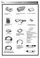
PROVIDED ACCESSORIES EN •Docking Station CU-V502U •Remote Control Unit RM-V716U •Cleaning Cloth •AC Power Adapter/Charger AA-V51U •DC Cord •MultiMediaCard (8 MB) (Already inserted in the camcorder) •Audio/Video Cable (ø3.5 mini-plug to RCA plug) •Audio Cable x 2 (for connection of an optional external microphone and headphones) •Editing Cable (One plug has 3 rings around the pin, and the other has 1 ring around the pin.
EN How To Use Audio Cables When using an optional external microphone or headphones, connect to the provided Audio cable (with a core filter attached), then connect the Audio cable to the camcorder. The core filter reduces interference. Microphone Headphones To AV OUT Core Filter Audio cable To MIC Core Filter AUTOMATIC DEMONSTRATION Automatic Demonstration takes place when “DEMO. MODE” is set to “ON” (factory-preset).
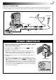
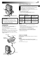
GETTING STARTED EN Battery pack BN-V507U or BN-V514U POWER indicator CHARGE indicator To AC outlet Power This camcorder’s 2-way power supply system lets you choose the most appropriate source of power. Do not use provided power supply units with other equipment. CHARGING THE BATTERY PACK AC Power Adapter/Charger DC OUT connector Battery pack BN-V507U BN-V514U (optional) Charging time approx. 1 hr. 30 min. approx. 3 hrs.
EN 9 USING THE BATTERY PACK 1 1 Insert the terminal end 1 of the battery pack into the battery pack mount, then firmly push the end 2 of the battery pack in the direction of the arrow until it locks into place as shown in the illustration. •If the battery pack is attached in the wrong position, a malfunction may occur. To Detach The Battery Pack. . . .... while sliding down BATT. RELEASE, detach it. Approximate recording time 2 BATT.
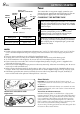
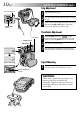
GETTING STARTED (cont.) EN Grip Adjustment Power Zoom Lever 1 2 3 START/STOP Button Separate the Velcro strip. Pass your right hand through the loop and grasp the grip. Adjust so that your thumb and fingers can easily operate the START/STOP Button and Power Zoom Lever. Refasten the Velcro strip. Viewfinder Adjustment Lock Button 1 Set the POWER Switch to “ ” while pressing down the Lock Button located on the switch and set the MODE Dial to any position. 2 3 Pull out the viewfinder fully.
EN Date/Time Settings POWER Lamp The date/time is recorded onto the tape at all times, but its display can be turned on or off during playback ( pg. 43). POWER Switch 1 Set the Operation Switch to “ ” and set the POWER Switch to “ ” while pressing down the Lock Button located on the switch, then open the LCD monitor fully or pull out the viewfinder fully. The POWER lamp lights and the camcorder is turned on. 2 3 4 Press the MENU wheel. The Menu Screen appears.
GETTING STARTED (cont.) EN Cassette holder cover Cassette holder Make sure the window side is facing out. Loading/Unloading A Cassette The camcorder needs to be powered up to load or eject a cassette. 1 Slide down and hold OPEN/EJECT in the direction of the arrow then pull the cassette holder cover open until it locks. The cassette holder opens automatically. •Do not touch internal components. 2 Insert or remove a tape and press “PUSH HERE” to close the cassette holder.
EN POWER Lamp 13 Recording Mode Setting Set the tape recording mode depending on your preference. POWER Switch 1 Set the Operation Switch to “ ” and set the POWER Switch to “ ” while pressing down the Lock Button located on the switch, then open the LCD monitor fully or pull out the viewfinder fully. The POWER lamp lights and the camcorder is turned on. 2 3 4 Press the MENU wheel. The Menu Screen appears.
GETTING STARTED (cont.) EN Loading A MultiMediaCard The provided MultiMediaCard is already inserted in the camcorder when you receive the camcorder. Card Cover Clipped edge Label 1 2 3 Make sure the camcorder’s power is off. 4 To close the card cover, push it until you hear a click. Open the card cover. Insert the MultiMediaCard clipped edge first. •Do not touch the terminal on the reverse side of the label. NOTES: ● Be sure to use only MultiMediaCards marked “ ”.
EN 15 Picture Quality/Size Mode Setting POWER Lamp POWER Switch Picture quality and size can be selected to best match your needs. Four different modes are available: XGA (1024 x 768 pixels) FINE, XGA STD, VGA (640 x 480 pixels) FINE and VGA STD, listed in order of quality. MODE Dial 1 Set the POWER Switch to “ ” while pressing down the Lock Button located on the switch and set the MODE Dial to “ ”, then open the LCD monitor fully. The POWER lamp lights and the camcorder is turned on.
GETTING STARTED (cont.) EN To turn on the camcorder, set the POWER Switch to any operation mode except “OFF” while pressing down the Lock Button located on the switch. Operation Mode Choose the appropriate operation mode according to your preference using the POWER Switch, Operation Switch and MODE Dial. POWER Switch Position POWER Lamp : Allows you to record on a tape or in the MultiMediaCard. POWER Switch Lock Button Operation Switch OFF: Allows you to switch off the camcorder.
EN MODE Dial Position MODE Dial DUAL VIDEO DU DS AL C PS MODE VIDEO The following indications appear in the upper left corner, depending on the MODE Dial position. DUAL DUAL : When set to “ DUAL ” No display : When set to “VIDEO” PS : When set to “ ” XGA or VGA : When set to “ ” (Progressive mode) 17 Function •Allows you to record video on a tape and store still images in a MultiMediaCard simultaneously ( pg. 26).
RECORDING Basic Recording For Video EN START/STOP Button POWER Switch POWER Lamp Lock Button MODE Dial NOTE: You should already have performed the procedures listed below. If not, do so before continuing. ● Power ( pg. 8) ● Grip Adjustment ( pg. 10) ● Viewfinder Adjustment ( pg. 10) ● Load A Cassette ( pg. 12) ● Recording Mode Setting ( pg.
EN 19 NOTES: ● When you use the LCD monitor outdoors in direct sunlight, the LCD monitor may be difficult to see. If this happens, use the viewfinder instead. ● The image will not appear simultaneously in the LCD monitor and the viewfinder. ● The cassette holder cannot be opened unless a power supply is attached. ● There may be a delay after you open the cassette holder cover until the cassette holder opens. Do not use force. ● Once the cassette holder is closed, it recedes automatically.
RECORDING Basic Recording For Video (cont.) EN MENU Wheel Snapshot (For Video Recording) POWER Switch MODE Dial This feature lets you record still images that look like photographs onto a tape. SNAPSHOT MODE SELECTION Lock Button 1 Set the POWER Switch to “ ” while pressing down the Lock Button located on the switch and the MODE Dial to “VIDEO” or “ ”, then set the Operation Switch to “ ”. Pull out the viewfinder fully or open the LCD monitor fully. 2 3 4 5 Press the MENU wheel.
RECORDING Basic Recording For Digital Still Camera (D.S.C.) MENU Wheel POWER Switch EN 21 Basic Shooting (Snapshot) You can use your camcorder as a Digital Still Camera for taking snapshots. MODE Dial NOTE: Lock Button SNAPSHOT Button Total number of shots Displays the approximate total number of shots that can be stored, including those already taken. The number increases or decreases depending on the shots stored, the Picture Quality/Size mode, MODE Dial setting, etc.
RECORDING Basic Recording For Video And D.S.C. EN FEATURE: Zooming Zoom in (T: Telephoto) 1 xW PURPOSE: T 1 0 xW T 20xW T 40xW T To produce the zoom in/out effect, or an instantaneous change in image magnification. OPERATION: Zoom out (W: Wide angle) Zoom display 10x W T Digital zoom zone 10X (optical) zoom zone Approximate zoom ratio Power Zoom Lever POWER Switch Zoom In Slide the Power Zoom Lever towards “T”. Zoom Out Slide the Power Zoom Lever towards “W”.
EN 23 NOTE: Recording From The Middle Of A Tape Time Code During recording, a time code is recorded on the tape. This code is to confirm the location of the recorded scene on the tape during playback. If recording starts from a blank portion, the time code begins counting from “00:00:00” (minute:second:frame). If recording starts from the end of a previously recorded scene, the time code continues from the last time code number. To perform Random Assemble Editing ( pg. 70 – 75), time code is necessary.
RECORDING Advanced Features For Video And D.S.C. EN Progressive Mode Recording START/STOP Button MODE Dial POWER Switch Lock Button This mode lets you record moving images (successive jitter-free still images) onto a tape. Images can then played back jitter-free, with superior quality. High-resolution still images can also be processed on a personal computer or can be printed out ( pg. 61).
EN 25 Description of Progressive Scan CCD Progressive Scan is a special image sensing method which, unlike conventional interlace scanning, is able to pick up all the lines of picture information in one Scan. Since the Progressive Scan CCD is capable of outputting 60 full Frames* per second — twice the amount of conventional systems — it is able to deliver a high quality picture even when its output signal is converted to a format that can be viewed on a TV screen.
EN RECORDING Advanced Features For Video And D.S.C. (cont.) Dual Shooting FOCUS K LIGHT BAC S EXPO URE FOCUS Button (3) MENU Wheel Lets you record images on a tape and store still images in a MultiMediaCard simultaneously. In other words, it is possible to store still images in the MultiMediaCard without interrupting image recording on the tape. 1 Set the POWER Switch to “ ” while pressing down the Lock Button located on the switch and the MODE Dial to “ DUAL ” .
EN Focus detection zone While focusing on a further subject While focusing on a nearer subject FOCUS FOCUS 27 FEATURE: Auto Focus PURPOSE: The camcorder’s Full Range AF system offers continuous shooting ability from close-up (as close as approx. 5 cm (2") to the subject) to infinity. However, correct focus may not be obtainable in the situations listed below (in these cases use manual focusing): •When two subjects overlap in the same scene. •When illumination is low.
RECORDING Advanced Features For Video And D.S.C. (cont.) EN POWER Switch Lock Button Operation Switch MENU Wheel Display FAD E R / W I P E 4 Menu Screen W I P E – S CRO L L W I P E – S HU T T E R RANDOM OF F F AD E R –WH I T E F AD E R – B L ACK F AD E R – B . W Using Menus For Detailed Adjustment This camcorder is equipped with an easy-to-use, on-screen menu system that simplifies many of the more detailed camcorder settings ( pg. 29 – 31) .
EN 29 Menu Screen Explanations FADER/WIPE Refer to “Fade/Wipe Effects” ( pg. 36, 37). P.AE/EFFECT Refer to “Program AE With Special Effects” ( pg. 38). W.BALANCE Refer to “White Balance Adjustment” and “Manual White Balance Operation” ( pg. 41). REC MODE Allows you to set the recording mode (SP or LP) depending on your preference ( pg. 13). SOUND MODE 12 BIT Enables video recording of stereo sound on four separate channels, and is recommended for use when performing audio dubbing.
CAMERA MENU RECORDING Advanced EN Menu Screen Explanations (cont.) DEMO. MODE DIS Features For Video And D.S.C. (cont.) ON Demonstrates certain functions such as Program AE with special effects, etc., and can be used to confirm how these functions operate. When “DEMO. MODE” is set to “ON” and the Menu Screen is closed, demonstration starts. Performing any operation during the demonstration stops the demonstration temporarily.
DISPLAY MENU MANUAL MENU EN WIND CUT FLASH OFF Disengages the function which cuts down on noise created by wind. ON Helps cut down on noise created by wind. “ sound will change. This is normal. 31 ” appears. The quality of the Refer to “Snapshot Flash” ( pg. 32). FLASH ADJ. Refer to “Flash Brightness Adjustment” ( pg. 33). ON SCREEN LCD Keeps the camcorder’s display (except the date, time and time code) from appearing on the connected TV screen.
RECORDING Advanced Features For Video And D.S.C. (cont.) EN MENU Wheel Snapshot Flash POWER Switch Lock Button Operation Switch SNAPSHOT Button Display MANUA L ME NU 1R E T URN DIS S E L F – T I ME R 5S T E L E MACRO AU T O W I D E MOD E AU T O W I ND CU T ON F L ASH OF F F L A S H AD J . The flash can be used when a snapshot is taken in RecordStandby ( pg. 20, 21). •In Full Auto mode, the flash automatically fires if it is dark ( appears).
EN Flash Brightness Adjustment POWER Switch Lock Button Operation Switch MENU Wheel Display MANUA L MENU 1R E T URN DIS S E L F – T I ME R 5S T E L E MACRO W I D E MOD E W I ND CU T F L ASH 2 F L A S H AD J . 33 Menu Screen When a snapshot ( pg. 20, 21) is taken in the dark the camcorder fires the flash ( pg. 32) and adjusts the brightness automatically. You can also adjust the flash brightness manually. When you find that the snapshots you took look too bright or too dark, adjust it manually.
EN RECORDING Advanced Features For Video And D.S.C. (cont.) Self-Timer MENU Wheel START/STOP Button POWER Switch Lock Button Once the camcorder is set, the camcorder operator can become part of the scene in a more natural way, adding the final touch to a memorable picture. 1 Set the Operation Switch to “ ” and set the POWER Switch to “ ” while pressing down the Lock Button located on the switch, then pull out the viewfinder or open the LCD monitor fully.
EN 5-Second Recording MENU Wheel START/STOP Button Operation Switch POWER Switch Lock Button Record a vacation or an important event in 5-second clips to keep the action moving. This function is available only for video recording. 1 Set the POWER Switch to “ ” while pressing down the Lock Button located on the switch and set the MODE Dial to “VIDEO”, “ ” or “ DUAL ”, then set the Operation Switch to “ ”. Pull out the viewfinder fully or open the LCD monitor fully. 2 3 4 5 6 Press the MENU wheel.
EN RECORDING Advanced Features For Video And D.S.C. (cont.) Fade/Wipe Effects These effects let you make pro-style scene transitions. Use them to spice up the transition from one scene to the next. You can also vary transitions from scene to scene. IMPORTANT: Some Fade/Wipe Effects cannot be used with certain modes of Program AE with special effects ( 墌 pg. 38). If an unusable Fade/Wipe Effect is selected, its indicator blinks or goes out.
EN 37 Fader And Wipe Menu Menu FADER — WHITE FADER — BLACK Effect Fade in or out with a white screen. Fade in or out with a black screen. FADER — B.W Fade in to a color screen from a black and white screen, or fade out from color to black and white. WIPE — CORNER Wipe in on a black screen from the upper right to the lower left corner, or wipe out from lower left to upper right, leaving a black screen.
RECORDING Advanced Features For Video And D.S.C. (cont.) EN IMPORTANT: Some modes of Program AE with special effects cannot be used with certain Fade/Wipe Effects ( 墌 pg. 37). If an unusable mode is selected, its indicator blinks or goes out. MENU Wheel 1 Set the Operation Switch to “ ”, then set the POWER Switch to “ ” while pressing down the Lock Button located on the switch. Pull out the viewfinder fully or open the LCD monitor fully. 2 3 4 Press the MENU wheel. The Menu Screen appears.
EN 39 Digital Sound Effects 12 sound effects (EXPLOSION, SIREN, LAUGHTER, RACE CAR, DOOR BELL, BUZZER, FANFARE, APPLAUSE, CHEERS, BOING, SCREAM and JEERS) pre-stored in the provided MultiMediaCard can be dubbed onto a tape. SOUND EFFECT MODE SELECTION INDEX Button 1 2 Load the provided MultiMediaCard (墌 pg. 14) and a cassette (墌 pg. 12). 3 4 Press INDEX. The SOUND Index Screen appears. Press the MENU wheel. The selection is complete.
EN RECORDING Advanced Features For Video And D.S.C. (cont.) Exposure Control Iris Lock Manual exposure adjustment is recommended in the following situations: • When shooting using reverse lighting or when the background is too bright. • When shooting on a reflective natural background such as at the beach or when skiing. • When the background is overly dark or the subject light. Use this function in the following situations: • When shooting a moving subject.
EN 41 White Balance Adjustment Manual White Balance Operation A term that refers to the correctness of color reproduction under various lighting. If the white balance is correct, all other colors will be accurately reproduced. The white balance is usually adjusted automatically. However, more advanced camcorder operators control this function manually to achieve a more professional color/tint reproduction. Perform Manual White Balance when shooting under various types of lighting.
PLAYBACK Basic Playback For Video EN Play/Pause Button (4/6) FOCUS K LIGHT BAC EXPOSURE Fast-Forward Button (3) Rewind Button (2) POWER Switch Stop Button (5) Power Zoom Lever (VOL.) MENU Wheel Speaker Lock Button 1 2 Load a tape (墌 pg. 12). Set the POWER Switch to “ ” while pressing down the Lock Button located on the switch. To start playback, press 4/6. •To stop playback, press 5. •Press 2 to rewind, or 3 to fast-forward the tape during Stop mode. To Control The Speaker Volume . . . ....
PLAYBACK Advanced Features For Video Lock Button MENU Wheel Display V I D EO MENU 1R E T URN 43 Using Menus For Detailed Adjustment POWER Switch Menu Screen SOUND MOD E S T E R EO 1 2 B I T MOD E SOUND L SOUND R S Y NCHRO R E C MOD E B L ANK S RCH COP Y D I S P L A Y ME NU 1R E T URN ON S CR E E N D A T E / T I ME T I ME COD E O F F ON The following procedure applies to all except Synchro Comp ( 墌 pg. 74, 75).
PLAYBACK Advanced Features For Video (cont.) EN Playback Sound During playback, the camcorder detects the sound mode in which the recording was made, and plays the sound back. Select the type of sound to accompany your playback picture. According to the menu access explanation on pg. 43, select “SOUND MODE” or “12BIT MODE” from the Menu Screen and set it to the desired parameter. SOUND MODE 12BIT MODE STEREO Sound is output on both “L” and “R” channels in stereo.
EN Blank Search Stop Button (5) MENU Wheel POWER Switch Lock Button Display V I D EO MENU 1R E T URN SOUND MOD E 1 2 B I T MOD E S Y NCHRO R E C MOD E B L ANK S RCH C A N C E L COP Y E X E C U T E 44 BLANK SEARCH 45 Menu Screen Helps you find where you should start recording in the middle of a tape to avoid time code interruption (墌 pg. 23). 1 Load a tape (墌 pg. 12) and set the POWER Switch to “ ” while pressing down the Lock Button located on the switch. 2 3 4 5 Press the MENU wheel.
PLAYBACK Advanced Features For Video (cont.) EN E-Mail Clip Recording START/STOP Button POWER Switch You can make video clips from recorded video footage and store them in a MultiMediaCard as files which can be conveniently sent via e-mail. Lock Button 1 Load a MultiMediaCard (墌 pg. 14) and cassette (墌 pg. 12). Set the POWER Switch to “ ” while pressing down the Lock Button located on the switch. 2 3 Press 4/6 to start video playback.
PLAYBACK Basic Playback For D.S.C. FOCUS K LIGHT BAC EXPOSURE Normal Playback Fast-Forward Button (3) Rewind Button (2) Images shot with the camcorder are automatically numbered, then stored in numerical order in the MultiMediaCard. You can view the stored images, one at a time, much like flipping through a photo album. POWER Switch 1 2 Load a MultiMediaCard (墌 pg. 14). 3 Press 3 to display the next image. Press 2 to display the previous image.
PLAYBACK Basic Playback For D.S.C. (cont.) EN Type of file Directory and File names Selected file Index number EXIT Picture Quality/Size mode: Appears only when displaying still images IMAGE 100-DVC00003 VGA 001 F 002 S 003 S 004 F 005 F 006 F Index Screen The files you stored can be displayed together with their index information.
EN 49 Index Playback You can view or listen to the files (still images, video clips, or sound effects) stored in memory six at a time. Use this mode when looking for a file you wish to view or hear.
PLAYBACK Advanced Features For D.S.C. EN POWER Switch Lock Button MENU Wheel Protecting Files The Protect mode helps prevent the accidental erasure of files. When a padlock mark is displayed next to the index number, that file cannot be deleted. 1 Set the POWER Switch to “ MEMORY ” while pressing PLAY down the Lock Button located on the switch. Open the LCD monitor fully or pull out the viewfinder fully. •A stored file is displayed. 2 Press the MENU wheel. The Menu Screen appears.
EN POWER Switch Lock Button MENU Wheel Deleting Files Previously stored files can be deleted either one at a time or all at once. 1 Set the POWER Switch to “ MEMORY ” while pressing PLAY down the Lock Button located on the switch. Open the LCD monitor fully or pull out the viewfinder fully. •A stored file is displayed. 2 Press the MENU wheel. The Menu Screen appears. Rotate it to select “ ” and press it. “MEMORY MENU” appears. 3 By rotating the MENU wheel... ... select “IMAGE DEL.
PLAYBACK Advanced Features For D.S.C. (cont.) EN POWER Switch Lock Button MENU Wheel Display MEMOR Y MENU 1R E T URN Menu Screen I MAGE P RO . I MAGE D E L . SOUND P RO . SOUND D E L . E – C L I P P RO . E – CL I P DE L . F RAME D E L . D PO F F ORMA T Initializing A MultiMediaCard You can initialize a MultiMediaCard anytime. After initialising, all images and data stored in the MultiMediaCard, including those which have been protected, are cleared.
EN 53 Superimposing A Print Frame A selection of print frames are stored in the camcorder. A frame can be superimposed over a still image. 1 2 3 PRINT FRAME Button MENU Wheel Display EXIT FRAME FRAME 5 001 002 003 004 005 006 Print Frame Index Screen Play back an image stored in the MultiMediaCard. Press PRINT FRAME. The Print Frame Index Screen appears. Rotate the MENU wheel to move the green frame to the desired print frame and press it. Selection is complete.
PLAYBACK Advanced Features For D.S.C. (cont.) EN POWER Switch Lock Button Print Frame Deletion A print frame created on a PC can be transferred to a MultiMediaCard using the provided software. Print frames that have been transferred to a MultiMediaCard can be deleted when they are no longer needed. There are 2 ways of deleting previously created print frames: by browsing through print frames individually or by deleting them all at once.
EN POWER Switch Lock Button MENU Wheel Display MEMOR Y MENU 1R E T URN I MAGE P RO . I MAGE D E L . SOUND P RO . SOUND D E L . E – C L I P P RO . E – CL I P DE L . F RAME D E L . CANC E L D PO F AL L F ORMA T S E L EC T MEMORY MENU CANC E L E X E CU T E Menu Screen Deletion Confirmation Screen 55 TO DELETE ALL PRINT FRAMES 1 2 3 Perform steps 1 through 4 on pag. 54. Rotate the MENU wheel to select “ALL” and press it. The Deletion Confirmation Screen appears.
PLAYBACK Advanced Features For D.S.C. (cont.) EN POWER Switch Lock Button Setting Print Information (DPOF Setting) This camcorder is compatible with the DPOF (Digital Print Order Format) standard in order to support future systems such as automatic printing, which records information about the still images you wish to print (such as the number of prints to make).
POWER Switch Lock Button EN TO PRINT BY SELECTING STILL IMAGES AND NO. OF PRINTS 1 2 Perform steps 1 through 4 on pg. 56. 3 4 Rotate the MENU wheel to move the green frame to the image you wish to print and press it. 5 Rotate the MENU wheel upward to select “EXIT” and press it. Selection is complete. The Confirmation Screen appears. 6 Rotate the MENU wheel to select “EXECUTE” and press it. The normal playback screen appears.
CONNECTIONS Basic Connections EN These are some basic types of connections. When making the connections, refer also to your VCR and TV instruction manuals. Connection toVCR a TV or VCR A.A.Connection to a TV or equipped withequipped an S-VIDEO with IN andan A/VS-VIDEO input IN and A/V input connectors connectors When connecting to a TV or VCR, use the provided Docking Station, an optional Audio/Video cable and S-Video cable.
EN 1 2 Make sure all units are turned off. 3 4 5 Connect the VCR output to the TV input, referring to your VCR’s instruction manual. Connect the camcorder to a TV or VCR as shown in the illustration (墌 pg. 58). If using a VCR . . . go to step 3. If not . . . go to step 4. Turn on the camcorder, the VCR and the TV. Set the VCR to its AUX input mode, and set the TV to its VIDEO mode. To choose whether or not the following displays appear on the connected TV . . . •Date/Time ....
CONNECTIONS Advanced Connections EN PC with DV connector-equipped capture board PC Connection To A Personal Computer This camcorder can transfer still images to a PC by using the provided software when connected as shown in the illustration. It is also possible to transfer still images to a PC with a DV connector-equipped capture board installed. To RS-232C To DV connector Core filter Make sure the camcorder and PC are turned off.
EN POWER Switch OD UAL D Lock Button To DV IN/OUT Core filter DV cable (optional) Core filter To DV connector Video unit equipped with a DV input connector To PC connector Digital Printer Core filter PC connection cable (provided) To RS-232C PC Connection To A Video Unit Equipped With A DV Connector Connection to the GV-DT3 Digital Printer (optional) allows you to print out images or transfer them to a PC.
DUBBING EN POWER Switch OD 1 2 UAL D Lock Button Red to AUDIO R OUT Yellow to VIDEO OUT* To S-VIDEO OUT White to AUDIO L OUT Audio/ Video cable [RCA plug to RCA plug] (optional) S-Video cable (optional) White to AUDIO L IN Red to AUDIO R IN Yellow to VIDEO IN* Dubbing To A VCR To S-VIDEO IN VCR TV * Connect when an S-Video cable is not used. Following the illustration, connect the camcorder and the VCR. Also refer to pg. 58 and 59.
EN 63 Dubbing To Or From A Video Unit Equipped With A DV Connector (Digital Dubbing) UAL D OD It is also possible to copy recorded scenes from the camcorder onto another video unit equipped with a DV connector. Since a digital signal is sent, there is little if any image or sound deterioration. [To use this camcorder as a player] Lock Button POWER Switch Open the connector cover. 1 2 Make sure the camcorder’s power is off. 3 4 Press 4 to play back the source tape.
DUBBING (cont.) EN POWER Switch Lock Button Dubbing Images Stored In A MultiMediaCard To A Tape Images can be dubbed from a MultiMediaCard to a tape. 1 2 Load a MultiMediaCard (墌 pg. 14) and cassette (墌 pg. 12). 3 To locate the point where you wish to dub a still image, play back the tape. Stop playback at the desired point. 4 Set the POWER Switch to “ MEMORY PLAY ” while pressing down the Lock Button located on the switch. To select a still image to be dubbed, perform Index Playback (墌 pg.
EN POWER Switch Dubbing Images Recorded On A Tape To A MultiMediaCard Lock Button Images can be dubbed from a tape to a MultiMediaCard. 1 2 MENU Wheel Play/Pause Button (4/6) Set the POWER Switch to “ ” while pressing down the Lock Button located on the switch. Open the LCD monitor fully or pull out the viewfinder fully. Press the MENU wheel. The Menu Screen appears. Rotate it to select “ ” and press it. “VIDEO MENU” appears. 4 Rotate the MENU wheel to select “ COPY” and press it.
USING THE REMOTE CONTROL UNIT EN 1 The Full-Function Remote Control Unit can operate this camcorder from a distance as well as the basic operations (Playback, Stop, Pause, Fast-Forward and Rewind) of your VCR. It also makes additional playback functions possible. 3 Tab Installing The Batteries The remote control uses two “AAA (R03)” size batteries. See “General Battery Precautions” ( pg. 93). 2 1 2 3 + – + Insert two “AAA (R03)” size batteries in the correct direction.
EN 1 0 2 4 6 8 67 ! 3 5 @ $ ^ * 7 9 # % & ( ) Functions Buttons With the camcorder’s POWER Switch set to the camera position (“ ”) . 1 Infrared beam transmitting window Transmits the beam signal. 2 Zoom (T/W) Buttons Zoom in/out ( pg. 22) With the camcorder’s POWER ” or Switch set to “ “ MEMORY PLAY ”. Zoom in/out ( pg. 68) pg. 71 pg. 68, 70 pg. 68 pg.
EN USING THE REMOTE CONTROL UNIT (cont.) FEATURE: Slow-Motion Playback PURPOSE: To allow slow-speed search in either direction during video playback. OPERATION: Remote sensor 1) To change from normal to Slow-Motion Playback, press SLOW (9 or 0) more than approx. 2 seconds. After approx. 1 minute in Slow Rewind or approx. 2 minutes in Slow Forward, normal playback resumes. To stop Slow-Motion Playback, press PLAY (4).
EN P L A Y BACK E F F E C T 4O F F 1 2 3 4 5 C L A S S I C F I LM MONO T ON E SEP I A S T ROB E V I D EO E CHO Remote sensor PLAYBACK EFFECT Select Menu 69 FEATURE: Playback Special Effects PURPOSE: To allow you to add creative effects to the video playback image. OPERATION: 1) To start playback, press PLAY (4). 2) Point the remote control at the camcorder's remote sensor and press EFFECT. The PLAYBACK EFFECT Select Menu appears. 3) Move the highlight bar to the desired effect by pressing EFFECT.
USING THE REMOTE CONTROL UNIT (cont.) EN Random Assemble Editing [R.A.Edit] Create edited videos easily using your camcorder as the source player. You can select up to 8 “cuts” for automatic editing, in any order you like. R.A.Edit is more easily performed when the MBR (Multi-Brand Remote) is set to operate with your brand of VCR (see VCR CODE LIST), but can also be performed by operating the VCR manually. Before operation, make sure the batteries are installed in the remote control ( pg. 66).
EN 71 MAKE CONNECTIONS Also refer to pg. 58 and 59. 1 A JVC VCR equipped with a remote pause connector . . . ... connect the editing cable to the Remote PAUSE connector. A JVC VCR not equipped with a remote pause connector but equipped with an R.A. EDIT connector . . . ... connect the editing cable to the R.A.EDIT connector.
EN USING THE REMOTE CONTROL UNIT (cont.) SELECT SCENES Program 1–– 2 3 4 5 6 7 8 OU T IN –– : ––~ ~ ~ ~ ~ ~ ~ ~ MODE Random Assemble Editing Menu T I ME COD E – – : – – TOT A L 00 : 00 Remote sensor PLAY FADE/WIPE EFFECT EDIT IN/OUT R.A.EDIT ON/OFF CANCEL 4 Point the remote control at the camcorder’s remote sensor. Press PLAY (4) and then press R.A.EDIT ON/ OFF on the remote control. The Random Assemble Editing Menu appears.
EN 73 AUTOMATIC EDITING TO VCR START/STOP Button 1 2 3–– 4 5 6–– 7 8 IN 00 : 25~ 07 : 18~ 03 : 33~ 09 : 30~ 15 : 55~ –– : ––~ ~ ~ OU T MODE 02 : 05 –– 08 : 31–– –– 05 : 53 13 : 15 16 : 20–– –– 13 Press START/STOP on the camcorder. Editing proceeds as programed, right through to the end of the last registered scene. •Pressing START/STOP on the remote control does not start editing. •When dubbing is complete, the camcorder enters the Pause mode, and the VCR enters its RecordPause mode.
EN USING THE REMOTE CONTROL UNIT (cont.) For More Accurate Editing Program 1 1–– 2 3 4 5 6 7 8 IN OU T –– : ––~ ~ ~ ~ ~ ~ ~ ~ MODE Random Assemble Editing Menu T I ME COD E – – : – – TOT A L 00 : 00 TV Some VCRs make the transition from Record-Pause to Record mode faster than others. Even if you begin editing for the camcorder and the VCR at exactly the same time, you may lose scenes you wanted, or find that you have recorded scenes you did not want.
EN ADJUSTMENT OF VCR/CAMCORDER TIMING MENU Dial 4 Point the remote control at the camcorder’s remote sensor and press R.A.EDIT ON/OFF to make the Random Assemble Editing menu disappear, then press the MENU wheel. The Menu Screen appears. 5 Rotate the MENU wheel to select “ ” and press it. “VIDEO MENU” appears. Then, rotate it to “SYNCHRO” and press it. The value for “SYNCHRO” is highlighted. 6 Based on the diagnostics performed ( pg.
USING THE REMOTE CONTROL UNIT (cont.) EN Audio Dubbing Display 6e Audio Dub Standby mode The audio track can be customized only when recorded in the 12-bit mode ( pg. 29). NOTES: ● Audio Dubbing is not possible on a tape recorded in 16bit audio, on a tape recorded in the LP mode or on a blank portion of a tape. ● To perform Audio Dubbing while watching on the television, make connections ( pg. 58).
EN Audio Dubbing Using Digital Sound Effects Display 6e EXPLOS I ON 77 Audio Dub Standby mode MENU Wheel POWER Switch Lock Button 1 2 Load the provided MultiMediaCard ( pg. 14) and perform step 1 and 2 of page 76. 3 4 Press PLAY (4) to begin Audio Dubbing. 5 Press STOP (5) to end Audio Dubbing. MODE Dial Press EDIT IN/OUT so that “ ” appears. •To select the sound effect, press INDEX to display the SOUND Index Screen ( pg. 49), then use the MENU wheel to select the desired sound effect.
USER MAINTENANCE EN After Use Cleaning The Camcorder 1 2 1 To clean the exterior, wipe gently with a soft cloth. Put the cloth in diluted mild soap and wring it well to wipe off heavy dirt. Then wipe again with a dry cloth. 2 Open the LCD monitor. Wipe gently with a soft cloth. Be careful not to damage the monitor. Close the LCD monitor. 3 4 5 To clean the lens, blow it with a blower brush, then wipe gently with lens cleaning paper. Turn off the camcorder.
TROUBLESHOOTING EN 79 If, after following the steps in the chart below, the problem still exists, please consult your nearest JVC dealer. The camcorder is a microcomputer-controlled device. External noise and interference (from a TV, a radio, etc.) might prevent it from functioning properly. In such cases, first disconnect its power supply unit (battery pack, AC Power Adapter/Battery Charger, etc.) and wait a few minutes; and then re-connect it and proceed as usual from the beginning.
EN TROUBLESHOOTING (cont.) SYMPTOM POSSIBLE CAUSES CORRECTIVE ACTION 11. The color of Snapshot looks strange. 11. • The light source or the subject does not include white. Or there are various different light sources behind the subject. • The Sepia or Monotone mode is activated. 11. • Set “FLASH” to “ON” in the Menu Screen. Or find a white subject and compose your shot so that it also appears in the frame (墌 pg. 20, 21, 32). • Turn off Sepia and Monotone (墌 pg. 38). 12.
EN 81 SYMPTOM POSSIBLE CAUSES 17. Program AE with special effects and Fade/Wipe Effects do not work. 17. • The Operation Switch is set to “ ”. 17. • Set the Operation Switch to “ ” (墌 pg. 36, 38). 18. The Black & White Fader does not work. 18. • The Sepia or Monotone mode is activated. 18. • Turn off Sepia and Monotone (墌 pg. 36, 38). 19. The Dissolve function does not work. 19. • The Sepia, Monotone or Slow Shutter mode of Program AE with special effects is activated.
EN SYMPTOM TROUBLESHOOTING (cont.) POSSIBLE CAUSES CORRECTIVE ACTION 24. Even when Slow Shutter is not selected, the image looks like it is activated. 24. • When shooting in the dark, the unit becomes highly sensitive to light and the image takes on an effect similar to Slow Shutter. 24. • If you want the lighting to look more natural, set GAIN UP to “AGC” or “OFF” in the Menu Screen (墌 pg. 29). 25. There is no strobe when the Classic Film or Strobe mode is activated. 25.
EN 83 SYMPTOM POSSIBLE CAUSES CORRECTIVE ACTION 35. The LCD monitor or viewfinder indications blink. 35. • Certain Fade/Wipe effects, certain modes of Program AE with special effects, “DIS” and other functions that cannot be used together are selected at the same time. 35. • Re-read the sections covering Fade/Wipe effects, Program AE with special effects and “DIS” (墌 pg. 30, 36 – 38). 36. Colored bright spots appear all over the LCD monitor or the viewfinder. 36.
TROUBLESHOOTING (cont.) EN SYMPTOM 45. An unusual mark appears. POSSIBLE CAUSES 45. ———— CORRECTIVE ACTION 45. • Check the section of the manual that explains LCD monitor/viewfinder indications (墌 pg. 88 – 92). 46. An error indication (E01 — E06) appears. 46. • A malfunction of some kind has occurred. In this case the camcorder’s functions become unusable. 46. • Remove the power supply (battery pack, etc.) and wait a few minutes for the indication to clear.
INDEX Docking Station 5 EN 85 7 6 1 2 8 9 3 ! 0 4 1 PC Connector [DIGITAL STILL] ............ 墌 pg. 60 2 J Terminal/Edit Connector [JLIP (Joint Level Interface Protocol) (EDIT)] ................... 墌 pg. 61 •Connect to a JLIP-compatible camcorder or VCR to control it from the computer using the provided Software. NOTE: Make sure that the camcorder is turned on while connecting the camcorder to a PC using the Docking Station’s JLIP connector.
INDEX Controls, Connectors And Indicators EN 123 # EXPOSURE $ 7 o FOCUS 5 6 K LIGHT BAC 4 ^ % u i 8 90! @ Q O W E p R & T * t Y y ( ) I U P a w e d r s q
EN 87 Controls Connectors 1 PRINT Button The connectors w to r are located beneath a cover. w Digital Video Connector [DV IN/OUT] (i.link*) .................................... 墌 pg. 60, 61, 63 * i.Link refers to the IEEE1394-1995 industry specification and extensions thereof. The logo is used for products compliant with the i.Link standard. e •Audio/Video Output Connector [AV OUT] ......................................... 墌 pg. 58 • Headphone Connector [ ] .............. 墌 pg.
INDEX Indications EN LCD Monitor/Viewfinder Indications During Video Recording Only 1 1 2 3* 4* 5 SP 3 5 REC 444 AN I M . MOD E SOUND 1 2 B I T TC 2 3 : 2 5 0 9 8 7 6 Displays the selected Fade/Wipe effect. (墌 pg. 36, 37) 2 Appears when in the Squeeze, Cinema or PS Wide mode. (墌 pg. 30) 3*Displays the recording mode (SP or LP). (墌 pg. 13) (墌 pg. 18) 4*Displays the tape remaining time. 5 • “REC” appears during recording. • “PAUSE” appears during Record-Standby mode. (墌 pg.
EN 89 LCD Monitor/Viewfinder Indications During Both Video And D.S.C. Recording 0 ! 2 4 6 1* 3 5 7 @ F . AU T O T PS 4 0 x W E X P L OS I ON 3 P HO T O 2 8 9 1*Appears when the Operation switch 2 3 4 5 6 7 8 9 $ % ^ & BRI GH T is set to “ ”. (墌 pg. 16) Displays the shooting mode position. (墌 pg. 17) Appears when backlight compensation is used. (墌 pg. 40) Appears when “FLASH” is set to “AUTO ” in the Menu Screen. (墌 pg. 32) Appears when the white balance is adjusted. (墌 pg.
INDEX Indications (cont.) EN LCD Monitor/Viewfinder Indications During Video Playback 1 2 3 4 5 1 2 B I T / SOUND 1 LP L E X P L OS I ON 4 1 2 3 4 B L ANK S E ARCH VO L UME 1. TC 1 0 : 0 6 : 2 0 8 7 1. 00 12 : 00 5 6 7 6 8 Displays the sound mode. (墌 pg. 43, 44) Displays the selected Digital Sound Effect. (墌 pg. 39) Displays the tape speed. (墌 pg. 13) Appears while a tape is running.
EN 91 Warning Indications Indications Function Displays the battery remaining power. Remaining power level: high Remaining power level: exhausted As the battery power comes close to nil, the battery indicator blinks. When the battery power is exhausted, power turns off automatically. (墌 pg. 12) Appears when no tape is loaded. CHECK TAPE’S ERASE PROTECTION SWITCH HEAD CLEANING REQUIRED USE CLEANING CASSETTE Appears when the erase protection tab is set to “SAVE” while the POWER Switch is set to “ ”.
EN Indications INDEX Indications (cont.) Function COPYING FAILED ● Appears if dubbing of copyguarded signals is attempted while this camcorder is being used as a recorder. ● Appears in the following cases when dubbing from a tape to a MultiMediaCard (as digital stills or video clips): – when no MultiMediaCard is loaded. – when the MultiMediaCard's memory is full. – when the MultiMediaCard is not formatted.
CAUTIONS EN When using the AC Power Adapter/Charger in areas other than the USA 䡲 The provided AC Power Adapter/Charger features automatic voltage selection in the AC range from 110 V to 240 V. USING HOUSEHOLD AC PLUG ADAPTER In case of connecting the unit’s power cord to an AC wall outlet other than American National Standard C73 series type use an AC plug adapter, called a “Siemens Plug”, as shown. For this AC plug adapter, consult your nearest JVC dealer.
EN MultiMediaCards To properly use and store your MultiMediaCards, be sure to read the following cautions: 1. During use . . . .... make sure the MultiMediaCard bears the MultiMediaCard mark. .... make sure the MultiMediaCard is positioned properly when inserting. 2. While the MultiMediaCard is being accessed (during recording, playback, deletion, initialization, etc.) . . . .... never unload the MultiMediaCard and never turn off the camcorder. 3. Store MultiMediaCards . . . ....
EN How To Handle A CD-ROM •Take care not to soil or scratch the mirror surface (opposite to the printed surface). Do not write anything or put a sticker on either the front or back surface. If the CD-ROM gets dirty, gently wipe it with a soft cloth outward from the center hole using a circular motion. •Do not use conventional disc cleaners or cleaning spray. •Do not bend the CD-ROM or touch its mirror surface. •Do not store your CD-ROM in a dusty, hot or humid environment.
TERMS EN A F AC Power Adapter/Charger ..................... 墌 pg. 8, 9 Animation ................................................ 墌 pg. 35 Audio Dubbing ........................................ 墌 pg. 76 Auto Date ................................................. 墌 pg. 31 Auto Focus ............................................... 墌 pg. 27 Auto Playback .......................................... 墌 pg. 47 Auto Shut off ................................ 墌 pg. 19, 21, 42 Fade-In/Out .....................
EN 97 P T Picture Quality/Size Mode ........................ 墌 pg. 15 Picture Wipe/Dissolve ......................... 墌 pg. 36, 37 Playback Special Effects ............................ 墌 pg. 69 Playback Zoom ........................................ 墌 pg. 68 POWER Switch Position ........................... 墌 pg. 16 Print Frame Deletion ........................... 墌 pg. 54, 55 Printer ...................................................... 墌 pg. 61 Program AE With Special Effects ................ 墌 pg.
SPECIFICATIONS EN Camcorder For General Power supply Power consumption LCD monitor off, viewfinder on LCD monitor on, viewfinder off Dimensions (W x H x D) Weight Operating temperature Operating humidity Storage temperature Pickup Lens Filter diameter LCD monitor Viewfinder Speaker : DC 6.3 V DC 7.2 V (Using AC Power Adapter/Charger) (Using battery pack) : Approx. 4.6 W : Approx. 5.
EN 99 For Connectors Video output Audio output DV Input/output Headphone output : : : : 1 V (p-p), 75 Ω, analog 300 mV (rms), 1 kΩ, analog, stereo 4-pin, IEEE 1394 compliant ø3.5 mm, stereo AC Power Adapter/Charger AA-V51U Power requirement U.S.A. and Canada Other countries Power consumption Output Charge VTR Dimensions (W x H x D) Weight : AC 120 V`, 60 Hz : AC 110 V to 240 V`, 50 Hz/60 Hz : 23 W : : : : DC 7.2 V , 0.77 A , 1.8 A DC 6.3 V 68 mm x 45 mm x 110 mm (2-11/16" x 1-13/16" x 4-3/8") Approx.
EN GR-DVM90 VICTOR COMPANY OF JAPAN, LIMITED COPYRIGHT© 2000 VICTOR COMPANY OF JAPAN, LTD.