ENGLISH CONTENTS DIGITAL VIDEO CAMERA GR-DVX78A GR-DVX49A GR-DVX48A GR-DVX78EA GR-DVX48EA GR-DVX78SH GR-DVX48SH Please visit our Homepage on the World Wide Web and answer our Consumer Survey (in English only): http://www.jvc-victor.co.jp/english/index-e.html AUTOMATIC DEMONSTRATION 6 GETTING STARTED 7 – 16 VIDEO RECORDING & PLAYBACK 17 – 24 VIDEO RECORDING ............. 18 – 20 VIDEO PLAYBACK ............... 21 – 24 DIGITAL STILL CAMERA (D.S.C.) RECORDING & PLAYBACK 25 – 36 D.S.C. RECORDING .......
EN Dear Customer, Thank you for purchasing this digital video camera. Before use, please read the safety information and precautions contained in the following pages to ensure safe use of this product. Using This Instruction Manual •All major sections and subsections are listed in the Table Of Contents on the cover page. •Notes appear after most subsections. Be sure to read these as well. •Basic and advanced features/operation are separated for easier reference. It is recommended that you . . . ....
EN CAUTIONS: ● This camcorder is designed to be used with PAL-type colour television signals. It cannot be used for playback with a television of a different standard. However, live recording and LCD monitor/viewfinder playback are possible anywhere. ● Use the JVC BN-V507U/V514U battery packs and, to recharge them or to supply power to the camcorder from an AC outlet, use the provided multi-voltage AC Adapter and Power Cord.
EN SAFETY PRECAUTIONS Do not point the lens or the viewfinder directly into the sun. This can cause eye injuries, as well as lead to the malfunctioning of internal circuitry. There is also a risk of fire or electric shock. CAUTION! The following notes concern possible physical damage to the camcorder and to the user. When carrying, be sure to hold the camcorder firmly in your hand, with the grip strap securely around your wrist.
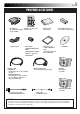
EN PROVIDED ACCESSORIES • AC Adapter • Remote Control Unit AP-V10A, AP-V10EA RM-V717U or AP-V10ED •Power Cord •Core Filter (GR-DVX49/DVX48 only) (for optional S-Video cable) Z pg. 6 for attachment • Editing Cable GR-DVX78: Both plugs have 1 ring around the pin. GR-DVX49/DVX48: One plug has 3 rings around the pin and the other has 1 ring around the pin. • Battery Pack BN-V507U • Memory Card 8 MB (GR-DVX78 only) (Already inserted in the camcorder) • Audio/Video Cable (ø3.
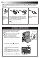
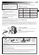
EN How To Attach The Core Filter (GR-DVX49/DVX48 only) (for optional S-Video cable) Attach the Core Filter (if provided with your model Z pg. 5) to an optional cable. The Core Filter reduces interference. 1 2 3 3 cm Stopper Wind once Release the stoppers on both ends of the Core Filter. Run the cable through the Core Filter, leaving approx. 3 cm of cable between the cable plug and the Core Filter. Wind the cable once around the outside of the Core Filter as shown in the illustration.
GETTING STARTED EN GETTING STARTED CONTENTS Power ................................................................ 8 – 9 Grip Adjustment ........................................................ 10 Viewfinder Adjustment ................................................ 10 Tripod Mounting ........................................................ 10 Date/Time Settings .................................................... 11 Loading/Unloading A Cassette .......................................
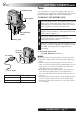
GETTING STARTED (cont.) EN CHARGE Lamp Power Switch 1 BATT. RELEASE Switch 2 Battery pack To DC IN connector 3 Open the cover. 5 To AC outlet Battery pack This camcorder’s 2-way power supply system lets you choose the most appropriate source of power. Do not use provided power supply units with other equipment.
EN 9 USING THE BATTERY PACK ATTENTION: Before detaching the power source, make sure that the camcorder’s power is turned off. Failure to do so can result in a camcorder malfunction. NOTES: ● Recording time is reduced significantly under the following conditions: • Zoom or Record-Standby mode is engaged repeatedly. • The LCD monitor is used repeatedly. ● Before extended use, it is recommended that you prepare enough battery packs to cover 3 times the planned shooting time.
GETTING STARTED (cont.) EN Grip Adjustment 1 2 3 Separate the Velcro strip. Pass your right hand through the loop and grasp the grip. Adjust your thumb and fingers through the grip, to easily operate the Recording Start/Stop button and Power Switch and Power Zoom Lever. Be sure to fasten the Velcro strip to your preference. Viewfinder Adjustment Power Switch Lock Button P 1 2 3 Set the Power Switch to “ ” or “ ” while pressing down the Lock Button located on the switch.
EN Date/Time Settings Power lamp Power Switch Lock Button OF LAY F Display OF F – LCD / TV – AU T O – OF F 2 0 . 12 . 01 17 : 3 0 RETURN CLOCK ADJ . 1 Set the Power Switch to “ ” while pressing down the Lock Button located on the switch, then open the LCD monitor fully or pull out the viewfinder fully. The power lamp lights and the camcorder is turned on. 2 3 4 Press the MENU Wheel in. The Menu Screen appears. Rotate the MENU Wheel to select “ DISPLAY”. Press it and the DISPLAY Menu appears.
GETTING STARTED (cont.) EN Loading/Unloading A Cassette Cassette holder cover Cassette holder The camcorder needs to be powered up to load or eject a cassette. 1 Slide down and hold OPEN/EJECT in the direction of the arrow then pull the cassette holder cover open until it locks. The cassette holder opens automatically. •Do not touch internal components. 2 Insert or remove a tape and press “PUSH HERE” to close the cassette holder. •Once the cassette holder is closed, it recedes automatically.
EN Recording Mode Setting Power lamp Power Switch Lock Button OF LAY F Display – SP LP CAMERA Menu Sub Menu GR-DVX78 only Set the tape recording mode depending on your preference. 1 Set the Power Switch to “ ” while pressing down the Lock Button located on the switch, then open the LCD monitor fully or pull out the viewfinder fully. The power lamp lights and the camcorder is turned on. 2 3 4 Press the MENU Wheel in. The Menu Screen appears.
GETTING STARTED (cont.) EN Loading A Memory Card (GR-DVX78 only) CARD OPEN The provided memory card is already inserted in the camcorder when you receive the camcorder. Card Cover 1 2 3 Make sure the camcorder’s power is off. 4 To close the card cover, push it until you hear a click. Slide CARD OPEN to open the card cover. Insert the memory card firmly clipped edge first. •Do not touch the terminal on the reverse side of the label. To Unload A Memory Card . . . ....
EN 15 Picture Quality Mode Setting (GR-DVX78 only) Power Switch Lock Button OF LAY F Display – F I NE STANDARD – VGA – AUTO 1 Set the Power Switch to “ ” while pressing down the Lock Button located on the switch, then open the LCD monitor fully or pull out the viewfinder fully. The power lamp lights and the camcorder is turned on. 2 3 4 Press the MENU Wheel in. The Menu Screen appears. P MENU Wheel QUAL I TY S I ZE UXGA The Picture Quality mode can be selected to best match your needs.
GETTING STARTED (cont.) EN To turn on the camcorder, set the Power Switch to any operation mode except “OFF” while pressing down the Lock Button located on the switch. VIDEO/DSC Switch (GR-DVX78 only) Choose the appropriate operation mode according to your preference using the Power Switch and VIDEO/DSC Switch (GR-DVX78 only). Power Switch Position (Manual): Allows you to set various recording functions using the Menus. If you want more creative capabilities than Full Auto recording, try this mode.
VIDEO RECORDING & PLAYBACK EN 17 VIDEO RECORDING & PLAYBACK CONTENTS VIDEO RECORDING ............................................ 18 – 20 Basic Recording ......................................................... 18 Journalistic Shooting ................................................... 19 Self-Recording .......................................................... 19 Zooming ................................................................ 19 Time Code ......................................................
VIDEO RECORDING EN Basic Recording Power Lamp VIDEO/DSC Switch (GR-DVX78 only) Power Switch Lock Button P OF LAY F Recording Start/ Stop Button NOTE: You should already have performed the procedures listed below. If not, do so before continuing. ● Power (Z pg. 8) ● Grip Adjustment (Z pg. 10) ● Viewfinder Adjustment (Z pg. 10) ● Load A Cassette (Z pg. 12) ● Recording Mode Setting (Z pg.
EN 19 Journalistic Shooting In some situations, different shooting angles may provide more dramatic results. Hold the camcorder in the desired position and tilt the LCD monitor in the most convenient direction. It can rotate 270° (90° downward, 180° upward). Self-Recording You can shoot yourself while viewing your own image in the LCD monitor. Open the LCD monitor and tilt it upward 180° so that it faces forward, then point the lens toward yourself and start recording.
VIDEO RECORDING (cont.) EN Time Code During recording, a time code is recorded on the tape. This code is to confirm the location of the recorded scene on the tape during playback. If recording starts from a blank portion, the time code begins counting from “00:00:00” (minute:second:frame). If recording starts from the end of a previously recorded scene, the time code continues from the last time code number. To perform Random Assemble Editing (Z pg. 69 – 73), time code is necessary.
VIDEO PLAYBACK Play/Pause Button (4/6) Rewind Button (2) Fast-Forward Button (3) Stop Button (5) VIDEO/DSC Switch (GR-DVX78 only) Power Switch PLAY O Lock Button Power Zoom Lever (Speaker Volume Control) (VOL.) FF Speaker EN 21 Normal Playback 1 2 Load a tape (Z pg. 12). Set the VIDEO/DSC Switch to “VIDEO” (GR-DVX78 only), then set the Power Switch to “ ” while pressing down the Lock Button located on the switch. To start playback, press 4/6. •To stop playback, press 5.
VIDEO PLAYBACK (cont.) EN Connections These are some basic types of connections. When making the connections, refer also to your VCR and TV instruction manuals. A. Connection to a TV or VCR equipped only with A/V input (RCA type) connectors To TV or VCR TV White to AUDIO L IN** Red to AUDIO R IN** VCR To AV IN/OUT*** or AV OUT*** Audio/Video cable [mini-plug to RCA plug] (provided) Yellow to VIDEO IN * When connecting the cables, open this cover.
EN 1 2 Make sure all units are turned off. 3 4 5 Connect the VCR output to the TV input, referring to your VCR’s instruction manual. Connect the camcorder to a TV or VCR as shown in the illustration (Z pg. 22). If using a VCR . . . go to step 3. If not . . . go to step 4. Turn on the camcorder, the VCR and the TV. Set the VCR to its AUX input mode, and set the TV to its VIDEO mode. To choose whether or not the following displays appear on the connected TV . . . •Date/Time ....
VIDEO PLAYBACK (cont.) EN Blank Search Stop Button (5) VIDEO/DSC Switch (GR-DVX78 only) Power Switch PLAY O Lock Button FOCUS/BLANK Button FF Helps you find where you should start recording in the middle of a tape to avoid time code interruption (Z pg. 20). 1 2 Load a tape (Z pg. 12). 3 Press FOCUS/BLANK.
DIGITAL STILL CAMERA (D.S.C.) RECORDING & PLAYBACK EN 25 DIGITAL STILL CAMERA (D.S.C.) RECORDING & PLAYBACK The D.S.C. (Digital Still Camera) features are available on GR-DVX78. CONTENTS D.S.C. RECORDING ..................................... 26 – 27 Basic Shooting (Snapshot) ...................................... 26 – 27 D.S.C. PLAYBACK ....................................... 28 – 36 Normal Playback (Of Images) ........................................ 28 Auto Playback (Of Images) ......................
D.S.C. RECORDING EN Basic Shooting (Snapshot) VIDEO/DSC Switch Power Switch Lock Button You can use your camcorder as a Digital Still Camera for taking snapshots. P NOTE: You should already have performed the procedures listed below. If not, do so before continuing. ● Power (Z pg. 8) ● Grip Adjustment (Z pg. 10) ● Viewfinder Adjustment (Z pg. 10) ● Loading A Memory Card (Z pg. 14) ● Picture Quality/Image Size Mode Setting (Z pg.
EN PIN-UP Pin-Up mode* 27 To Delete Unwanted Still Images . . . .... when unwanted still images are stored in the memory card or its memory is full, refer to “Deleting Files” (Z pg. 32) and delete unwanted still images. To Remove The Shutter Sound . . . .... when you do not want to hear the shutter sound, set “BEEP” to “OFF” in the Menu Screen (Z pg. 38, 40). The sound is no longer heard from the speaker.
D.S.C. PLAYBACK EN Play/Pause Button (4/6) Normal Playback (Of Images) Images shot with the camcorder are automatically numbered, then stored in numerical order in the memory card. You can view the stored images, one at a time, much like flipping through a photo album. Rewind Button (2) Fast-Forward Button (3) Stop Button (5) Power Switch 1 2 PLAY O Lock Button FF 3 VIDEO/DSC Switch [For Normal Playback] [For Auto Playback] To display the next image Display 100-0010 10 / 24 10.10.
EN To view video clips (Z␣ pg. 61) stored in a memory card . . . … during normal playback of image, press SELECT (Z␣ pg.␣ 86 and 87, @ SELECT Button) once to engage the video clip mode. “E-CLIP” appears. Then pressing 4/6 can allow you to view the video clips in the LCD monitor or viewfinder; video clips cannot be displayed on a connected TV. Total number • You can look for the desired file using Index Screen of files (Z␣ below and pg.␣ 30).
D.S.C. PLAYBACK (cont.) EN SELECT Button INDEX Button Index Playback You can view or listen to the files (still images, video clips (Z pg. 61), or sound effects (Z pg. 56, 67)) stored in memory six at a time. Use this mode when looking for a file you wish to view or hear. 1 2 Perform steps 1 and 2 of “Normal Playback” on pg. 28. 3 4 Press INDEX. The Index Screen appears.
EN VIDEO/DSC Switch Power Switch PLAY O Lock Button FF Protecting Files The Protect mode helps prevent the accidental erasure of files. When a padlock mark is displayed next to the index number, that file cannot be deleted. 1 Set the VIDEO/DSC Switch to “ ”, then set the Power Switch to “ ” while pressing down the Lock Button located on the switch. Open the LCD monitor fully or pull out the viewfinder fully. •A stored image file is displayed. To protect the image file . . . … go to step 2.
D.S.C. PLAYBACK (cont.) EN VIDEO/DSC Switch Power Switch PLAY O Lock Button Deleting Files Previously stored files can be deleted either one at a time or all at once. 1 Set the VIDEO/DSC Switch to “ ”, then set the Power Switch to “ ” while pressing down the Lock Button located on the switch. Open the LCD monitor fully or pull out the viewfinder fully. •A stored image file is displayed. To delete the image file . . . … go to step 2. To delete the video clip file. . . .
EN 33 TO DELETE THE DISPLAYED FILE Before doing the following, perform steps 1 through 3 on page 32. 4 Rotate the MENU Wheel to select “CURRENT” and press it. The Deletion Confirmation Screen appears. 5 Rotate the MENU Wheel to select “EXECUTE” and press it. The currently displayed file is deleted. •If “CURRENT FILE IS PROTECTED” appears, the file is protected and cannot be deleted (Z pg. 31). •To cancel deletion, rotate the MENU Wheel to select “CANCEL” and press it.
D.S.C. PLAYBACK (cont.) EN Setting Print Information (DPOF Setting) VIDEO/DSC Switch Power Switch PLAY O Lock Button FF MENU Wheel Display DPOF Menu DPOF – SELECT AL L RESET DPOF AL L – CANCEL EXECUTE Confirmation Screen This camcorder is compatible with the DPOF (Digital Print Order Format) standard in order to support future systems such as automatic printing, which records information about the still images you wish to print (such as the number of prints to make).
EN TO PRINT BY SELECTING STILL IMAGES AND NO. OF PRINTS Power Switch PLAY O Lock Button FF MENU Wheel Number of prints Display EXIT DPOF 100-DVC00021 VGA 19 00 20 00 21 03 22 00 23 00 24 00 DPOF SE L ECT – CANCEL EXECUTE DPOF Index Screen Confirmation Screen 1 2 Perform steps 1 through 4 on pg. 34. 3 4 Rotate the MENU Wheel to move the green frame to the image you wish to print and press it. 5 Rotate the MENU Wheel upward to select “EXIT” and press it. Selection is complete.
D.S.C. PLAYBACK (cont.) EN Initialising A Memory Card VIDEO/DSC Switch Power Switch PLAY O Lock Button FF MENU Wheel Display MEMORY Menu PROTEC T DELE T E DPOF FORMAT CANCEL EXECUTE You can initialise a memory card anytime. After initialising, all files and data stored in the memory card, including those which have been protected, are cleared. 1 Set the VIDEO/DSC Switch to “ ”, then set the Power Switch to “ ” while pressing down the Lock Button located on the switch.
ADVANCED FEATURES EN 37 ADVANCED FEATURES CONTENTS USING MENUS FOR DETAILED ADJUSTMENT .......... 38 – 44 For Recording Menu ............................................. 38 – 41 For Playback Menu ............................................. 42 – 44 FOR RECORDING ....................................... 45 – 56 Night-Scope ............................................................. 45 Program AE With Special Effects .............................. 46 – 47 Fade/Wipe Effects .............................
USING MENUS FOR DETAILED ADJUSTMENT EN For Recording Menu Lock Button This camcorder is equipped with an easy-to-use, on-screen menu system that simplifies many of the more detailed camcorder settings (Z pg. 39 – 41). P 1 Set the Power Switch to “ ” while pressing down the Lock Button located on the switch. Open the LCD monitor fully or pull out the viewfinder fully. 2 3 Press the MENU Wheel in. The Menu Screen appears. 4 Function menu setting depends on the function.
EN 39 Menu Screen Explanations WIPE/FADER Refer to “Fade/Wipe Effects” (Z pg. 48, 49). PROGRAM AE Refer to “Program AE With Special Effects” (Z pg. 46, 47). W.BALANCE Refer to “White Balance Adjustment” and “Manual White Balance Operation” (Z pg. 53). REC MODE Allows you to set the recording mode (SP or LP) depending on your preference (Z pg. 13). SOUND MODE 12 BIT Enables video recording of stereo sound on four separate channels, and is recommended for use when performing audio dubbing.
EN USING MENUS FOR Menu Screen Explanations (cont.) MANUAL WIDE MODE DETAILED ADJUSTMENT (cont.) OFF Records with no change in the screen ratio. For playback on a TV with a normal screen ratio. CINEMA Inserts black bands at the top and bottom of the screen. During playback on wide-screen TVs, the black bands at the top and bottom of the screen are appears. When using this cut and the screen ratio becomes 16:9. mode, refer to your wide-screen TV’s instruction manual.
EN MIC/AUX Enables sound input from camcorder’s stereo microphone or AV IN/OUT connector, when Audio Dubbing (Z pg. 66) is executed. “MIC” or “AUX” appears on the Audio Dubbing screen depending on the sound input you use. D.SOUND Enables sound effect input recorded on the provided memory card, when Audio Dubbing (Z pg. 67) is executed. CAM RESET CANCEL Does not reset all settings to the factory-preset.
EN USING MENUS FOR DETAILED ADJUSTMENT (cont.) For Playback Menu Power Switch PLAY O Lock Button 1 Set the Power Switch to “ ” while pressing down the Lock Button located on the switch. Open the LCD monitor fully or pull out the viewfinder fully. 2 3 Press the MENU Wheel in. The Menu Screen appears. 4 5 6 Rotate the MENU Wheel to select the desired function, and press it to display the Sub Menu.
EN DISPLAY SYSTEM Menu Screen Explanations (cont.) Display ON SCREEN setting: SP 46 12B I T / SOUND1 For playback sound, tape speed and tape running during video playback. Each setting is linked with “ DISPLAY” or “ SYSTEM”, which appears when the Power Switch is set to “ ” (Z pg. 40, 41). The parameters are the same as in the description on pg. 40, 41. IMAGE 100-0001 6 For type of file, directory, file name, index number and total number during D.S.C. playback (GR-DVX78 only).
EN USING MENUS FOR DETAILED ADJUSTMENT (cont.) Playback Sound During playback, the camcorder detects the sound mode in which the recording was made, and plays the sound back. Select the type of sound to accompany your playback picture. According to the menu access explanation on pg. 42, select “SOUND MODE” or “12BIT MODE” from the Menu Screen and set it to the desired parameter. SOUND MODE 12BIT MODE STEREO Sound is output on both “L” and “R” channels in stereo.
FOR RECORDING EN 45 Night-Scope Makes dark subjects or areas even brighter than they would be under good natural lighting. Although the recorded image is not grainy, it may look as if it is strobing due to the slow shutter speed. NIGHT-SCOPE Button Power Switch Lock Button P 1 Set the Power Switch to “ ” while pressing down the Lock Button located on the Switch. Open the LCD monitor fully or pull out the viewfinder fully. 2 Press NIGHT-SCOPE so that the Night-Scope indicator “ ” appears.
FOR RECORDING (cont.) EN IMPORTANT: Some modes of Program AE with special effects cannot be used with certain Fade/Wipe Effects (Z pg. 48, 49). If an unusable mode is selected, its indicator blinks or goes out.
EN SHUTTER (Variable Shutter Speed) 1/50 – The shutter speed is fixed at 1/50th of a second. Black bands that usually appear when shooting a TV screen become narrower. 1/120 – The shutter speed is fixed at 1/120th of a second. The flickering that occurs when shooting under a fluorescent light or mercury-vapour lamp is reduced. 47 MONOTONE Like classic black and white films, your footage is shot in B/W. Used together with the Cinema mode, it enhances the “classic film” effect.
FOR RECORDING (cont.) EN Fade/Wipe Effects These effects let you make pro-style scene transitions. Use them to spice up the transition from one scene to the next. You can also vary transitions from scene to scene. IMPORTANT: Some Fade/Wipe Effects cannot be used with certain modes of Program AE with special effects (Z pg. 46, 47). If an unusable Fade/ Wipe Effect is selected, its indicator blinks or goes out.
EN 49 Fader And Wipe Menu Menu FADER — WHITE FADER — BLACK FADER — B.W MOSAIC Effect Fade in or out with a white screen. Fade in or out with a black screen. Fade in to a colour screen from a black and white screen, or fade out from colour to black and white. Fade in or out with a full-screen mosaic effect. WIPE — CORNER Wipe in on a black screen from the upper right to the lower left corner, or wipe out from lower left to upper right, leaving a black screen.
FOR RECORDING (cont.) EN VIDEO/DSC Switch (GR-DVX78 only) Power Switch Lock Button This feature lets you record still images that look like photographs onto a tape. SNAPSHOT MODE SELECTION 1 Set the VIDEO/DSC Switch to “VIDEO” (GR-DVX78 only), then set the Power Switch to “ ” while pressing down the Lock Button located on the switch. Open the LCD monitor fully or pull out the viewfinder fully. 2 3 4 5 Press the MENU Wheel in. The Menu Screen appears.
EN Focus detection zone While focusing on a further subject 51 While focusing on a nearer subject Manual focus indicator FEATURE: Auto Focus PURPOSE: The camcorder’s Full Range AF system offers continuous shooting ability from close-up (as close as approx. 5 cm to the subject) to infinity. However, correct focus may not be obtainable in the situations listed below (in these cases use manual focusing): •When two subjects overlap in the same scene. •When illumination is low.
FOR RECORDING (cont.) EN Exposure Control Iris Lock Manual exposure control is recommended in the following situations: • When shooting using reverse lighting or when the background is too bright. • When shooting on a reflective natural background such as at the beach or when skiing. • When the background is overly dark or the subject is bright. 1 Set the Power Switch to “ ” while pressing down the Lock Button located on the switch. Open the LCD monitor fully or pull out the viewfinder fully.
EN 53 White Balance Adjustment Manual White Balance Operation A term that refers to the correctness of colour reproduction under various lighting. If the white balance is correct, all other colours will be accurately reproduced. The white balance is usually adjusted automatically. However, more advanced camcorder operators control this function manually to achieve a more professional colour/tint reproduction. Perform Manual White Balance when shooting under various types of lighting.
FOR RECORDING (cont.) EN Snapshot Flash (GR-DVX78 only) SNAPSHOT Button Power Switch Lock Button P OF LAY F MENU Wheel Display MANUAL Menu F LA SH – AU T O AUTO ON OF F The flash can be used when a snapshot is taken in Record-Standby mode (Z pg. 26, 50). • When the Power Switch is set to “ ”, the flash automatically fires if it is dark ( appears). • When the Power Switch is set to “ ”, you can select the “FLASH” setting as follows: AUTO : Fires automatically if it is dark ( appears).
EN 55 Flash Brightness Adjustment (GR-DVX78 only) Power Switch Lock Button P OF LAY F MENU Wheel Display MANUAL Menu F LA SH AD J. – +2 When a snapshot (Z pg. 26, 50) is taken in the dark the camcorder fires the flash (Z pg. 54) and adjusts the brightness automatically. You can also adjust the flash brightness manually. When you find that the snapshots you took look too bright or too dark, adjust it manually.
FOR RECORDING (cont.) EN D.SOUND PLAY Button INDEX Button Digital Sound Effects (GR-DVX78 only) 12 sound effects (EXPLOSION, SIREN, LAUGHTER, RACE CAR, DOOR BELL, BUZZER, FANFARE, APPLAUSE, CHEERS, BOING, SCREAM and JEERS) prestored in the provided memory card can be dubbed onto a tape.
DUBBING EN 57 Dubbing To Or From A VCR [To use this camcorder as a player] To S-VIDEO of jack box To AV IN/OUT*** or AV OUT*** Connector cover** S-Video cable Audio/Video cable [mini-plug to RCA plug] (provided) (optional) To AUDIO, VIDEO* IN or OUT**** To S-VIDEO IN or OUT**** VCR TV * Connect when an S-Video cable is not used. ** When connecting the cables, open this cover.
DUBBING (cont.) EN Dubbing To Or From A Video Unit Equipped With A DV Connector (Digital Dubbing) It is also possible to copy recorded scenes from the camcorder onto another video unit equipped with a DV connector. Since a digital signal is sent, there is little if any image or sound deterioration. [To use this camcorder as a player] To DV IN/OUT 1 Make sure all units are turned off.
EN Dubbing Still Images Stored In A Memory Card To A Tape (GR-DVX78 only) Rewind Button (2) Still images can be dubbed from a memory card to a tape. Fast-Forward Button (3) VIDEO/DSC Switch Power Switch PLAY O Lock Button SNAPSHOT Button Display TO COPY TO TAPE PUSH “ SNAPSHOT ” REC 59 FF 1 2 Load a memory card (Z pg. 14) and cassette (Z pg. 12). 3 Set the VIDEO/DSC Switch to “ ”, then set the Power Switch to “ ” while pressing down the Lock Button located on the switch.
DUBBING (cont.) EN Dubbing Still Images Recorded On A Tape To A Memory Card (GR-DVX78 only) Play/Pause Button (4/6) Still images can be dubbed from a tape to a memory card. VIDEO/DSC Switch Power Switch PLAY O Lock Button Load a memory card (Z pg. 14) and cassette (Z pg. 12). 3 Set the VIDEO/DSC Switch to “VIDEO”, then set the Power Switch to “ ” while pressing down the Lock Button located on the switch. 4 Press the MENU Wheel in. The Menu Screen appears.
EN 61 Dubbing Moving Images Recorded On A Tape To A Memory Card (E-Mail Clip Recording) (GR-DVX78 only) Play/Pause Button (4/6) E-MAIL CLIP REC Button You can make video clips from recorded video footage and store them in a memory card as files which can be conveniently sent via e-mail. Recording Start/Stop Button PLAY O MENU Wheel FF Power Switch Lock Button Display E - M AI L CL I P ST ANDB Y E - MA I L CL I P READY When the Recording Start/Stop Button is pressed.
USING THE REMOTE CONTROL UNIT EN 1 3 The Full-Function Remote Control Unit can operate this camcorder from a distance as well as the basic operations (Playback, Stop, Pause, Fast-Forward and Rewind) of your VCR. It also makes additional playback functions possible. Tab Installing The Batteries The remote control uses two “AAA (R03)” size batteries. See “General Battery Precautions” (Z pg. 93). 2 – + + – Remove the battery compartment cover while pushing up the tab as illustrated.
EN 1 0 2 4 6 8 63 ! 3 5 @ $ ^ * 7 9 # % & ( ) Functions Buttons With the camcorder’s Power Switch set to “ ” or “ ”. 1 Infrared beam transmitting window Transmits the beam signal. 2 Zoom (T/W) Buttons Zoom in/out (Z pg. 19) With the camcorder’s Power ”. Switch set to “ Zoom in/out (Z pg. 64) 3 DISPLAY Button — Z pg. 23, 57, 70 4 SHIFT Button — Z pg. 64, 69 5 SLOW Rewind/Forward Buttons — — Z pg. 64 Z pg. 64 6 REW Button — • Rewind/Reverse Shuttle Search on a tape (Z pg.
EN USING THE REMOTE CONTROL UNIT (cont.) FEATURE: Slow-Motion Playback PURPOSE: To allow slow-speed search in either direction during video playback. Remote sensor OPERATION: 1) To change from normal to Slow-Motion Playback, press SLOW (9 or 0) more than approx. 2 seconds. After approx. 1 minute in Slow Rewind or approx. 2 minutes in Slow Forward, normal playback resumes. n To stop Slow-Motion Playback, press PLAY (4).
EN PLA Y BACK E F F E C T OF F 1 2 3 4 5 C L A S S I C F I LM MONO T ON E SEP I A S T ROB E V I D EO E CHO Remote sensor PLAYBACK EFFECT Select Menu 65 FEATURE: Playback Special Effects PURPOSE: To allow you to add creative effects to the video playback image. OPERATION: 1) To start playback, press PLAY (4). 2) Point the remote control at the camcorder's remote sensor and press EFFECT. The PLAYBACK EFFECT Select Menu appears. 3) Move the highlight bar to the desired effect by pressing EFFECT.
EN USING THE REMOTE CONTROL UNIT (cont.) Audio Dubbing Display 6e MIC Audio Dub Standby mode The audio track can be customized only when recorded in the 12-bit mode (Z pg. 39). GR-DVX78 only NOTES: ● Audio Dubbing is not possible on a tape recorded in 16-bit audio, on a tape recorded in the LP mode or on a blank portion of a tape. ● To perform Audio Dubbing while watching on the television, make connections (Z pg. 22). Speaker Stereo microphone Remote sensor Located beneath the cover.
EN Display 6e Audio Dub Standby mode D.SOUND APPLAUSE Sound effect indication D.SOUND PLAY Button Audio Dubbing Using Digital Sound Effects (GR-DVX78 only) 1 2 3 4 Load the provided memory card (Z pg. 14) and perform step 1 and 2 of page 66. 5 Press INDEX to access the sound effects Index Screen. Rotate the MENU Wheel to select the desired sound effect and press it. 6 Press PLAY (4) to begin Audio Dubbing. The selected sound effect is dubbed onto the tape.
EN USING THE REMOTE CONTROL UNIT (cont.) Insert Editing You can record a new scene into a previously recorded tape, replacing a section of the original recording with minimal picture distortion at the in and outpoints. The original audio remains unchanged. Display 6w NOTES: ● Before performing the following steps, make sure that “TIME CODE” is set to “ON” in the Menu Screen (Z␣ pg.␣ 41,␣ 43). ● Insert Editing is not possible on a tape recorded in the LP mode or on a blank portion of a tape.
EN 69 Random Assemble Editing [R.A.Edit] Create edited videos easily using your camcorder as the source player. You can select up to 8 “cuts” for automatic editing, in any order you like. R.A.Edit is more easily performed when the MBR (Multi-Brand Remote) is set to operate with your brand of VCR (see VCR CODE LIST), but can also be performed by operating the VCR manually. Before operation, make sure the batteries are installed in the remote control (Z pg. 62).
EN USING THE REMOTE CONTROL UNIT (cont.) MAKE CONNECTIONS Also refer to pg. 22 and 23. 1 To JLIP*** or EDIT*** To S-VIDEO ... connect the editing cable to the Remote PAUSE connector. A JVC VCR not equipped with a Remote PAUSE connector but equipped with an R.A. EDIT connector . . . ... connect the editing cable to the R.A.EDIT connector. Connector cover** A VCR other than above . . . To AV IN/OUT**** or AV OUT**** ... connect the editing cable to the remote control’s PAUSE IN connector.
EN SELECT SCENES Program IN 1–– –– : –– 2 3 4 5 6 7 8 T I ME CODE TOTAL 71 MODE OUT ~ ~ ~ ~ ~ ~ ~ ~ Random Assemble Editing Menu –– : –– 0 0 : 00 Remote sensor PLAY FADE/WIPE EFFECT EDIT IN/OUT R.A.EDIT ON/OFF CANCEL 4 Point the remote control at the camcorder’s remote sensor. Press PLAY (4) and then press R.A.EDIT ON/ OFF on the remote control. The Random Assemble Editing Menu appears. 5 If using a Fade/Wipe at the beginning of the scene, press FADE/WIPE on the remote control.
USING THE REMOTE CONTROL UNIT (cont.) EN AUTOMATIC EDITING TO VCR PLAY O Recording Start/Stop Button IN 00 : 2 5 1 2 07 : 18 3 – – 0 3 : 33 09 : 30 4 15 : 55 5 6–– –– : –– 7 8 T I ME CODE TOTAL ~ ~ ~ ~ ~ ~ ~ ~ OUT MODE 02 : 05 –– 08 : 31 – – – – 05 : 53 13 : 15 16 : 29 – – – – 11 12 FF Point the remote control towards the VCR’s remote sensor and press VCR REC STBY (q6), or manually engage the VCR’s Record-Pause mode. 13 Press the Recording Start/Stop Button on the camcorder.
EN For More Accurate Editing Program 1 IN 1–– –– : –– 2 3 4 5 6 7 8 T I ME CODE TOTAL MODE OUT ~ ~ ~ ~ ~ ~ ~ ~ Random Assemble Editing Menu –– : –– 0 0 : 00 – Some VCRs make the transition from Record-Pause to Record mode faster than others. Even if you begin editing for the camcorder and the VCR at exactly the same time, you may lose scenes you wanted, or find that you have recorded scenes you did not want. For a cleanly edited tape, confirm and adjust the timing of the camcorder against your VCR.
SYSTEM CONNECTIONS EN [A] Using USB or PC connection cable GR-DVX49/DVX48 only PC connection cable (provided) To PC (DIGITAL PHOTO) USB cable (provided) To RS-232C To USB connector PC To USB GR-DVX78 only OR [B] Using DV cable DV cable (optional) To DV IN/OUT Core filter To DV connector Core filter PC with DV connector Open the connector cover.
EN 75 Connection To A Video Unit Equipped With A DV Connector Connection to the GV-DT3 Digital Printer (optional) allows you to print out images or transfer them to a PC. It is also possible to copy recorded scenes from the camcorder onto another video unit equipped with a DV connector. This function is called Digital Dubbing (Z pg. 58), which offers virtually no image or sound deterioration. Open the connector cover.
REFERENCES EN REFERENCES CONTENTS DETAILS ........................................................ 77 TROUBLESHOOTING .................................... 78 – 83 USER MAINTENANCE .......................................... 84 INDEX ................................................... 85 – 92 Jack Box ................................................................ 85 Controls, Connectors And Indicators ........................... 86 – 87 Indications .....................................................
DETAILS ITEMS ➪ Power (Z pg. 8) ➪ VIDEO RECORDING (Z pg. 18, 19) EN 77 NOTES ❍ Perform charging where the temperature is between 10°C and 35°C. 20°C to 25°C is the ideal temperature range for charging. If the environment is too cold, charging may be incomplete. ❍ Charging times are for a fully discharged battery pack. ❍ Charging time varies according to the ambient temperature and the status of the battery pack. ❍ To avoid interference with reception, do not use the AC Adapter near a radio.
TROUBLESHOOTING EN If, after following the steps in the chart below, the problem still exists, please consult your nearest JVC dealer. The camcorder is a microcomputer-controlled device. External noise and interference (from a TV, a radio, etc.) might prevent it from functioning properly. In such cases, first disconnect its power supply unit (battery pack, AC Adapter, etc.) and wait a few minutes; and then re-connect it and proceed as usual from the beginning. POSSIBLE CAUSES CORRECTIVE ACTION 1.
EN 79 SYMPTOM POSSIBLE CAUSES CORRECTIVE ACTION 10. The colour of Snapshot looks strange. 10. • The light source or the subject does not include white. Or there are various different light sources behind the subject. • The Sepia or Monotone mode is activated. 10. • Set “FLASH” to “ON” in the Menu Screen. Or find a white subject and compose your shot so that it also appears in the frame (Z pg. 26, 50, 54). • Turn off Sepia and Monotone (Z pg. 46, 47). 11.
EN SYMPTOM TROUBLESHOOTING (cont.) POSSIBLE CAUSES CORRECTIVE ACTION 16. Program AE with special effects and Fade/Wipe Effects do not work. 16. • The Power Switch is set to “ ”. 16. • Set the Power Switch to “ (Z pg. 16). 17. The Black & White Fader does not work. 17. • The Sepia or Monotone mode is activated. 17. • Turn off Sepia and Monotone (Z pg. 46, 48). 18. The Dissolve function does not work. 18.
EN SYMPTOM POSSIBLE CAUSES 81 CORRECTIVE ACTION 23. Even when Slow Shutter is not selected, the image looks like it is activated. 23. • When shooting in the dark, the unit becomes highly sensitive to light and the image takes on an effect similar to Slow Shutter. 23. • If you want the lighting to look more natural, set “GAIN UP” to “AGC” or “OFF” in the Menu Screen (Z pg. 39). 24. There is no strobe when the Classic Film or Strobe mode is activated. 24.
EN SYMPTOM TROUBLESHOOTING (cont.) POSSIBLE CAUSES CORRECTIVE ACTION 34. The LCD monitor or viewfinder indications blink. 34. • Certain Fade/Wipe effects, certain modes of Program AE with special effects, “DIS” and other functions that cannot be used together are selected at the same time. 34. • Re-read the sections covering Fade/Wipe effects, Program AE with special effects and “DIS” (Z pg. 39, 46 – 49). 35. Coloured bright spots appear all over the LCD monitor or the viewfinder. 35.
EN SYMPTOM 43. Blocks of noise appear during playback, or there is no playback picture and the screen becomes blue. 43. 44. The LCD monitor, the viewfinder and the lens have become dirty (ex. fingerprints). 44. 45. An unusual mark appears. 45. 83 POSSIBLE CAUSES CORRECTIVE ACTION ———— 43. • Clean the video heads with an optional cleaning cassette (Z pg. 94). ———— 44. • Wipe them gently with soft cloth. Wiping strongly can cause damage (Z pg. 84). ———— 45.
USER MAINTENANCE EN After Use Cleaning The Camcorder 1 2 1 To clean the exterior, wipe gently with a soft cloth. Put the cloth in diluted mild soap and wring it well to wipe off heavy dirt. Then wipe again with a dry cloth. 2 Open the LCD monitor. Wipe gently with a soft cloth. Be careful not to damage the monitor. Close the LCD monitor. 3 4 5 To clean the lens, blow it with a blower brush, then wipe gently with lens cleaning paper. Turn off the camcorder.
INDEX Jack Box EN (GR-DVX78: CU-V506) (GR-DVX49/DVX48: CU-V505) 1 1 2 2 3 3 1 USB Connector [USB] (GR-DVX78 only) ................................. Z pg. 74 PC Connector [PC (DIGITAL PHOTO)] (GR-DVX49/DVX48 only) .................... Z pg. 74 85 2 S-Video Output Connector [S-VIDEO] ................................ Z pg. 22, 57, 70 3 •EDIT Connector [EDIT] (GR-DVX78 only) .............................. Z pg. 70 Connect the editing cable when performing Random Assemble Editing ......... Z pg.
INDEX Controls, Connectors And Indicators EN 23 % * 1 4 u ^ & 5 y 6 OFF AY 9 8 PL 86 7 i o $ # @ ! 0 p R P E Q T Y w ( ) a t U I e r O s d q W
EN 87 Controls Connectors 1 E-MAIL CLIP REC Button (GR-DVX78 only) ................................. Z pg. 61 2 D. SOUND PLAY Button (GR-DVX78 only) ................................. Z pg. 56 3 •MENU Wheel [+, –, PUSH] ............... Z pg. 38 • LCD Monitor Brightness Control [+, –] .................................... Z pg. 18 4 •Power Zoom Lever [T/W] .................. Z pg. 19 • Speaker Volume Control [VOL.] ............................................... Z pg. 21 5 Power Switch [ , , , OFF] .......
INDEX Indications EN LCD Monitor/Viewfinder Indications During Video Recording Only 1 2 3 4 5 LP 50 min P R EC 6w SOUND 12B I T 20 : 5 5 0 9 8 7 6 1 Appears when in the Squeeze or Cinema mode. (Z pg. 40) 2 Displays the selected Fade/Wipe effect. (Z pg. 48, 49) 3 Rotates while the tape is running. (Z pg. 18) 4 Displays the recording mode (SP or LP). (Z pg. 13) 5 Displays the tape remaining time. (Z pg. 18) 6 • “REC” appears during recording. • “PAUSE” appears during Record-Standby mode.
EN 89 LCD Monitor/Viewfinder Indications During Both Video And D.S.C. Recording 9 0 1 2 5 3 4 6 7 40 x W ! T PHOTO 3 @ 3 BR I GHT 2 0 . 12 . 01 17 : 3 0 8 % 1 Appears when the Power Switch is set to “ ”. (Z pg. 16) 2 • : Appears when Night-Scope is engaged. (Z pg. 45) • : Appears when “GAIN UP” is set to “AUTO” and the shutter speed is automatically adjusted. (Z pg. 39) 3 : Appears when “FLASH” is set to “AUTO ” in the Menu Screen. (GR-DVX78 only) (Z pg.
INDEX Indications (cont.) EN LCD Monitor/Viewfinder Indications During Video Playback 1 2 3 4 5 S P 64 1 2B I T / SOUND 1 L MIC B L ANK SEARCH VO L UME 2 0 . 12 . 01 17 : 3 0 20 : 21 : 25 7 8 6 1 Displays the sound mode. (Z pg. 42, 44) 2 Displays the Blank Search mode. (Z pg. 24) Displays the selected Digital Sound Effect. (Z pg. 30, 56) 3 Displays the tape speed. (Z pg. 13) 4 Appears while a tape is running.
EN 91 Warning Indications Indications Function Displays the battery remaining power. Remaining power level: high Remaining power level: exhausted As the battery power comes close to nil, the battery indicator blinks. When the battery power is exhausted, power turns off automatically. Appears when no tape is loaded. CHECK TAPE’S ERASE PROTECTION TAB HEAD CLEANING REQUIRED USE CLEANING CASSETTE CONDENSATION OPERATION PAUSED PLEASE WAIT TAPE! TAPE END DIFFERENT FORMATTED TAPE (Z pg.
EN Indications INSERT ERROR! INDEX Indications (cont.) Function ● Appears if Insert Editing is attempted on a tape recorded in the LP mode. (Z pg. 68) ● Appears if INSERT (w) on the remote control is pressed when the erase protection tab is set to “SAVE”. (Z pg. 68) COPYING FAILED ● Appears if dubbing of copyguarded signals is attempted while this camcorder is being used as a recorder.
CAUTIONS General Battery Precautions If the remote control is not functioning even if it is being operated correctly, the batteries are exhausted. Replace them with fresh ones. Use only the following batteries: AAA (R03) size x 2 Please make note of the following rules for battery use. When misused, the batteries can leak or explode. 1. When replacing batteries, refer to page 62. 2. Do not use any different size of batteries from those specified. 3. Be sure to install batteries in the correct direction. 4.
EN Memory Cards To properly use and store your memory cards, be sure to read the following cautions: 1. During use . . . .... make sure the memory card bears the SD or MultiMediaCard mark. .... make sure the memory card is positioned properly when inserting. 2. While the memory card is being accessed (during recording, playback, deletion, initialisation, etc.) . . . .... never unload the memory card and never turn off the camcorder. 3. Store memory cards . . . ....
EN How To Handle A CD-ROM •Take care not to soil or scratch the mirror surface (opposite to the printed surface). Do not write anything or put a sticker on either the front or back surface. If the CD-ROM gets dirty, gently wipe it with a soft cloth outward from the centre hole using a circular motion. •Do not use conventional disc cleaners or cleaning spray. •Do not bend the CD-ROM or touch its mirror surface. •Do not store your CD-ROM in a dusty, hot or humid environment.
TERMS EN A F AC Adapter ............................................. Z pg. 8, 9 Analogue Input ................................... Z pg. 42, 57 Audio Dubbing ......................................... Z pg. 66 Auto Date ................................................. Z pg. 41 Auto Focus ................................................ Z pg. 51 Auto Playback ........................................... Z pg. 28 Auto Shut off ....................................... Z pg. 18, 27 Fade-In/Out .........
EN 97 P T Picture Quality Mode ................................ Z pg. 15 Picture Wipe/Dissolve ......................... Z pg. 48, 49 Playback Special Effects ............................ Z pg. 65 Playback Zoom ......................................... Z pg. 64 Power Switch Position .............................. Z pg. 16 Printer ....................................................... Z pg. 75 Program AE With Special Effects ......... Z pg. 46, 47 Protecting Files .......................................
SPECIFICATIONS EN Camcorder For General Power supply Power consumption LCD monitor off, viewfinder on LCD monitor on, viewfinder off Dimensions (W x H x D) Weight Operating temperature Operating humidity Storage temperature Pickup Lens Filter diameter LCD monitor Viewfinder Speaker : DC 11.0 V DC 7.2 V (Using AC Adapter) (Using battery pack) : Approx. 4.4 W (GR-DVX78), Approx. 4.0 W (GR-DVX49/DVX48) : Approx. 5.2 W (GR-DVX78), Approx. 4.
EN 99 For Connectors AV Video output Video input (GR-DVX78 only) Audio output Audio input (GR-DVX78 only) Headphone output (GR-DVX78 only) DV Input/output : : : : 1 V (p-p), 75 Ω, analogue 0.8 V (p-p) – 1.
EN GR-DVX78A GR-DVX49A GR-DVX48A GR-DVX78EA GR-DVX48EA GR-DVX78SH GR-DVX48SH VICTOR COMPANY OF JAPAN, LIMITED ®Registered Trademark owned by VICTOR COMPANY OF JAPAN, LTD. COPYRIGHT© 2001 VICTOR COMPANY OF JAPAN, LTD.