DIGITAL VIDEO PRINTER GV-DT1 ENGLISH Please visit our CyberCam Homepage on the World Wide Web and answer our Consumer Survey (in English only): http://www.jvc-victor.co.jp/index-e.
EN SAFETY PRECAUTIONS WARNING: TO PREVENT FIRE OR SHOCK HAZARD, DO NOT EXPOSE THIS UNIT TO RAIN OR MOISTURE. CAUTION n When you are not using the unit for a long period of time, it is recommended that you disconnect the power cord from the mains outlet. n Dangerous voltage inside. Refer internal servicing to qualified service personnel. To prevent electric shock or fire hazard, remove the power cord from the mains outlet prior to connecting or disconnecting any signal lead or aerial.
2 EN Some Do's And Don'ts On The Safe Use Of Equipment This equipment has been designed and manufactured to meet international safety standards but, like any electrical equipment, care must be taken if you are to obtain the best results and safety is to be assured. DO read the operating instructions before you attempt to use the equipment.
CAUTIONS Exercise caution when moving the printer. If you drop the unit, do not attempt to use it. If during use you notice that the cabinet is damaged, shut the printer down, unplug it and contact your JVC dealer. Use of the printer under these conditions can lead to fire or electric shock. DO NOT place heavy objects on the printer’s power cord, or leave the cord near any heatgenerating appliance, as this can damage the cord. Avoid excessive pulling or twisting of the power cord.
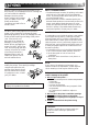
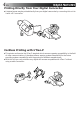
4 EN MAJOR FEATURES Printing Directly from Your Digital Camcorder ● A desired scene may be printed directly from your digital camcorder by connecting this unit to it with a DV connector. Cordless Printing with IrTran-P ● This printer conforms to the IrTran-P standard which ensures a greater compatibility in the field of video communications. It therefore offers a superior system extendibility for the future providing system compatibility with the products of different manufacturers.
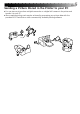
EN Sending a Picture Stored in the Printer to your PC ● You can store a picture from a digital camcorder or a digital still camera in the printer and transfer it to your PC. ● More creative printing work may be achieved by processing your picture data with the provided MGI PhotoSuite or other commercially available painting software.
6 CONTENTS EN CAUTIONS 3 MAJOR FEATURES 4 CONTROLS, INDICATORS AND CONNECTORS 8 Front View ....................................................................................... 8 Rear View .......................................................................................
EN PRINTING FROM the PC 7 33 How the Setup Dialog Works .............................................................. 34 How the Spooler Window Works ......................................................... 35 INDICATIONS AND MESSAGES 36 Lamp Indications ............................................................................. Printer Section ............................................................................... PC Printer Section .......................................................
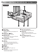
8 CONTROLS, INDICATORS AND CONNECTORS EN Front View 1 2345 6 7 8 9 0 ! 1 PRINT button 2 IrDA/DV button • Switches the video input between IrDA and DV. 3 STANDBY/ON button • Turns the printer on and off. 4 MEMORY button • Used to store a video picture delivered through the DV connector. 5 ON LINE button • Press this for video communications with your PC. 6 Vent holes • Periodically clean these holes with a vacuum cleaner. Make sure the printer’s power cord is unplugged.
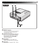
EN Rear View $ % ^ & $ PARALLEL Connector • Connect to the parallel (printer) terminal of a computer using a commercially available printer cable. % Service Door for Jammed Paper Removal • Open this door when paper is jammed. * Do not open this door unless paper is jammed. Be sure to close this after clearing the paper jam. DV connector ^ • Used to receive a video data from a digital camcorder with a DV connector. Power Cord & • Plug into an AC outlet (AC 220 – 240 V).
10 EN HOW TO MAKE CONNECTIONS (DV CONNECTION) Some televisions and video cassette recorders require a specific type of output cable. Refer to their instruction manuals for details on television and VCR connections to the GV-DT1. WHEN PRINTING FROM A DIGITAL CAMCORDER WITH A DV CONNECTOR Digital camcorder To DV connector DV cable (provided) Core Filter Connect the end provided with the Core Filter to the Printer.
HOW TO MAKE CONNECTIONS (IrDA RECEPTION) EN 11 WHEN PRINTING FROM AN IrTran-P COMPATIBLE DIGITAL STILL CAMERA IrTran-P (Infrared Transfer Picture): An infrared video data communications format which enables infrared communications of video data between compatible units of different manufacturers. IrTran-P compatible digital still camera Approx. 15° Approx. 15° Within an approx. 50 cm distance Data communications may not be possible between some units when they are too close or too distant.
12 INSTALLATION OF INK CASSETTE EN 1 Install the ink cassette included with the available blank paper sheet set.OF INK CASSETTE INSTALLATION CASSETTE DOOR 1 OPEN Pull the right top of the door in the direction indicated by the arrow to open it. UP SLACK 2 TAKE Turn the roller on the side with the “ 2 in the direction of the arrow. Do not turn the part marked with mark A ” mark . INK CASSETTE 3 INSTALL Insert the cassette label-side up from the end marked. Push it until you hear a click.
EN 13 About Blank Paper Sheet Sets (optional) You must use one of the sets shown in the following chart: SET CONTENTS PV-50SFAE (Standard type) • Standard Print Paper (50 Sheets) • Ink Cassette (50 Prints) Print your favorite images, just like snapshots. *PV-25SFSAE • 1-Picture Single-Print Sticker Paper (15 Sheets) • 16-Picture Multi-Print Sticker Paper (10 Sheets) • Ink Cassette (25 Prints) Make customized seals and stick them on greeting cards, envelopes, letters, etc.
14 LOADING THE PAPER TRAY EN Opening the paper tray A ● Open the lid while pushing A . Inserting blank paper sheets in the paper tray To printer Printing side Cautions Partition panel 1. Keep the partition panel upright. If it is tilted, get it upright by pushing the back of the paper tray. 2. Load print sheets in the tray, placing the side with the detection marks toward you, face down. •Sticker sheets are not provided with detection marks.
PREPARATION EN 15 ● Before printing, make sure everything is set up and ready. 1 Have a Blank Paper Sheet Set ready. (page 13) 2 Install the ink cassette in the printer (page 12) 3 Place the blank paper sheets in the paper tray and load the tray (page 14). ● Use print sheets and ink cassette from the same kit. 4 Open the output tray. 5 Connect image source to the printer (page 10). 6 Plug the printer’s power cable into an AC outlet and press the button.
16 EN PRINTING FROM A DIGITAL CAMCORDER (DV CONNECTION) Preparation ● See page 10 for connection. THE CAMCORDER TO PLAY 1 SET •Refer to the instruction manual of your camcorder. IrDA/DV MEMORY PRINT IrDA ON LINE DV THE IrDA/DV BUTTON OF THE 2 PRESS PRINTER •When the DV lamp is Blinking : Video data is being received by the printer. Lighting : Video data is not under reception. Check for proper connection referring to page 10.
EN IrDA/DV MEMORY PRINT IrDA ON LINE DV ON LINE 17 THE PRINT LAMP STOPS 5 WHEN BLINKING AND LIGHTS, PRESS THE PRINT BUTTON •The PRINT lamp blinks and printing starts. •Printing is finished when the print paper is discharged with the PRINT lamp lit. •If you want to print the same picture again, press the PRINT button again after printing has once finished. Every pressing of the PRINT button produces one print copy. •If you want to print another picture, repeat the steps 3 to 5.
18 EN PRINTING FROM A DIGITAL STILL CAMERA (IrDA RECEPTION) When using a digital still camera compatible with IrTran-P, please refer also to the instruction manual provided with the camera. Preparation When only storing a picture Remove the paper tray from the printer. IrDA/DV MEMORY PRINT ON LINE When storing and printing a picture Load the paper tray containing print sheets. When picture data is sent from the digital still camera, a copy is automatically printed.
EN 19 q Procedure from Picture Data Transmission to Printing The picture data sent from the digital still camera is automatically printed. The PRINT lamp lights and blinks as indicated below until printing is finished.
20 EN MEMO
EN 21 PERSONAL COMPUTER PRINTER SECTION q The Readme.TXT file provides additional information for setup and information that is not included in the instruction manual. Please read the file before installing the provided software program. q You can find the latest information (in English) on the provided software program at our www server: http://www.jvc-victor.co.jp/ q If you want to process the picture, see the Idea Guide of the MGI PhotoSuite included in the CD-ROM.
22 INTRODUCTION EN REQUIRED HARDWARE qBi-Directional 25-pin printer interface q486DX2 or higher CPU OPERATING ENVIRONMENT qPersonal computer with MicrosoftT* WindowsT* Operating System Version 3.1 (also verified to run with MicrosoftT WindowsT 95) * MicrosoftT and WindowsT are trademarks of the Microsoft Corporation registered in the United States and other countries.
EN 23 SOFTWARE FEATURES DRIVER WINDOW Print orientation, number of prints and image adjustment can be selected in this window. •Print orientation : Portrait/Landscape •No. of prints : 1 to 25 •Image adjustment Contrast : Low — High (11 grades from –5 — +5) Brightness : Dark — Bright (11 grades from –5 — +5) CAPTURE UTILITY WINDOW FOR IMAGE CAPTURING Images stored in the GV-DT1 can be processed and stored in your computer in the bitmap (BMP) format. Storage format File Extension: *.
24 PERIPHERAL UNIT CONNECTIONS EN Some televisions and video cassette recorders require a specific type of output cable. Refer to their instruction manuals for details on television and VCR connections to the GV-DT1. When Printing from PC q When connecting components, make sure all units are turned off.
HOW TO INSTALL THE SOFTWARE EN INSTALLING IN A WINDOWST COMPATIBLE PC 25 See the instruction manual of WindowsT or the PC in use for the basic operation of WindowsT. In the case of WindowsT 95 In the case of WindowsT 3.1 up WindowsT 95. 1 Start • If you have any other applications up WindowsT 3.1. 1 Start • If you have any other applications open, close them all. open, close them all. the “Driver & Capture Utility 2 Insert Software” into the floppy disk drive.
26 EN OPEN & CLOSE (Basic Operation Procedure) GETTING STARTED You can launch this program using the standard procedure for WindowsT. There are some differences between WindowsT 3.1 and WindowsT 95. WindowsT 3.1 offers a number of ways to launch an application. 1. Open the group of application icons on the program manger and double-click the application you want to open. 2. Select Run in the program manger, select the file name of the application and click the RUN button. 3.
EN 27 Once the program has loaded, WindowsT 3.1 displays the screen shown below. Icon button Control menu button File(F) Edit(E) Titlebar Image(I) Window(W) Maximize button Help(H) The titlebar and menubar look different on WindowsT 95. Icon button Control menu button File(F) Edit(E) Titlebar Image(I) Window(W) Close button Help(H) Maximize button CLOSING THE PROGRAM Double-click the control menu button in WindowsT 3.1 or click Close GV-DT1 Capture Utility (X) on the [File (F)] menu.
28 CONTROLS AND OPERATIONS EN MENUBAR File(F) Edit(E) Image(I) Window(W) Help Capture New(N) Save(S) Save As(A) Exit Capture Utility(X) The menubar provides several menus with lists of commands that enable you to execute various program functions. Click the desired item on the menubar to pull down the menu. Then click on the desired command in the pulldown menu. Some commands may not be executable depending on where you are in the program. Disabled functions look lighter than other items.
EN Edit(E) Select to undo the most recent work done. Select to copy to the clipboard. The copy is displayed in colour according to the monitor setup. Select to rotate through 90° clockwise. Select to rotate through 90° counterclockwise. Select to reduce the captured image to 1/4 or 1/16. Select to change the number of colours (colour grade scale) of the capture image.
30 CONTROLS AND OPERATIONS (cont.) EN Window(W) Arranges the captured images side by side and stacked one upon another. A maximum of four tiles are visible at one time. Arranges the captured images in cascade. Shows a maximum of four images overlapping one another. Arranges the minimized images side by side. Tile(T) Cascade(C) Arrange Icons 1 Capture1 2 Capture2 3 Capture3 4 Capture4 Temporary file names for the captured images.
PRINTING PROCEDURE 1 EN 31 Store the picture you want to transmit to the PC in the printer. TRANSMITTING 2 Capture the picture you want to print into the PC. 3 Work on the characters and other data with the MGI PhotoSuite provided or other optional software programs. 4 Start printing.
32 EN CAPTURING A PICTURE INTO the PC This is to capture a picture into the PC and display it on the monitor. Preparation: • Capture a picture from a digital camcorder or a digital still camera into the printer in advance. • See “Printing from a Digital Camcorder” (page 16) or “Printing from a Digital Still Camera” (page 18) for details of capturing. • The PRINT lamp lights when capturing into the printer is finished. 1. Press the printer ON LINE button to bring the on LINE lamp into lighting.
PRINTING FROM the PC EN 33 You cannot print the captured image with the provided Driver & Capture Utility Software. Use a commercially available Paint or other photo editing software program to print the image. Preparation: Capture the picture referring to “Capturing a Picture into the PC” on the previous page. 1. Work on the characters and other data with the MGI PhotoSuite provided or other commercially available painting software. •See the instruction manual provided with the software for details.
34 PRINTING FROM the PC (cont.) EN HOW THE SETUP DIALOG WORKS No. of prints 2 GV-DT1 Setup Dialog Orientation Print orientation 1 Number of Prints Portrait OK Landscape Cancel Image Adjustment Image adjustment 3 Normal(N) Low Contrast Dark Brightness Normal Help(H)… 2. 3. Bright Version(A) Normal 1. High 4 5 6 7 8 Print orientation Select when printing. Portrait : Select when printing a vertical image layout.
EN 35 HOW THE SPOOLER WINDOW WORKS GV-DT1 Spooler Information(I) Signal indicator box Help(H) 1 2 Message box 3 File name box Transmitting now. 1. Signal indicator box Red : Print data capture in pause. Blue : Print data capture in progress. 2. File name box Displays the name of the file or the application which you have specified for printing. 3. Message box Displays the current status. 4. Control button : Click to pause the spooler. : Click to re-open the spooler.
36 INDICATIONS AND MESSAGES EN Lamp Indications Lamp indication PRINT IrDA DV ON LINE v Appears when: m Recommended actions: v Ink running out or ink cassette not loaded. m Replace with new one or insert ink cassette. Reference pages 12 Blinking quickly PRINT IrDA DV ON LINE Blinking quickly PRINT IrDA DV ON LINE One of the input mode lamps lights during the blinking of the PRINT lamp. One of the following items applies. 1) v Rear door is open. m Close the rear door.
EN Lamp indication v Appears when: m Recommended actions: 37 Reference pages v IrDA data being received. PRINT IrDA DV ON LINE 18 19 Blinking v IrDA data being converted. PRINT IrDA DV ON LINE 18 19 Lighting Blinking PRINT IrDA DV ON LINE Lighting v Printing with IrDA reception finished. m Every pressing of the PRINT button after finishing printing produces another copy of the same picture. 18 19 Lighting PRINT IrDA DV v DV mode selected, with no picture stored in memory.
38 INDICATIONS AND MESSAGES (cont.) EN Lamp Indications (cont.) Lamp indication PRINT IrDA DV ON LINE Lighting v Appears when: m Recommended actions: v DV data converted. m Pressing the PRINT button allows printing of the stored picture. Every pressing of the PRINT button produces another copy of the same picture. Reference pages 16 17 Lighting v Ready to receive picture data from PC. PRINT IrDA DV ON LINE 32 Lighting PRINT IrDA DV v Picture data being captured from printer to PC.
EN 39 PRINTER SECTION If Check to see if Picture data cannot be transmitted through the DV connection v m v m v m Picture blurred when printed from the camcorder with the DV connector v Camcorder with the DV connector is in Still Picture mode. m When installing a picture from the camcorder by the DV connector to the printer, set the camcorder with the DV connector in Still Picture. Picture data cannot be transmitted through IrDA reception v Printer is in IrDA mode.
40 INDICATIONS AND MESSAGES (cont.) EN IF YOU HAVE THE FOLLOWING MEASSAGES ON THE DISPLAY PC PRINTER SECTION Message v Appears when: m Recommended actions Printer is internally overheated. Please wait. v Temperature in the printer rises too high for the installation environment, continuous printing and other reasons. m Wait a while until the message disappears. No ink cassette loaded. Set ink cassette and close cover. v The ink cassette is not installed or is improperly installed.
EN 41 IF YOU HAVE THE FOLLOWING MEASSAGES ON THE DISPLAY Message v Appears when: m Recommended actions Pull out paper tray and check paper. v The paper tray is running out of paper or paper feeding is not working. m Remove the paper tray and set print sheets correctly. Printer has malfunctioned unexpectedly. Printing will be cancelled. v Any abnormality occurs during printing. m Turn the power off, unplug the power cord, then plug the cord back in and turn the power on again.
42 TROUBLESHOOTING (cont.) EN OTHER PROBLEMS: This unit is a precision machine which includes a microprocessor. Its operational performance may be influenced by external noise or disturbance. If a normal operation cannot be achieved even after taking appropriate actions as defined below, the power should be turned off by unplugging the power cable. Then reconnect the power by plugging it in again and recheck for proper operation.
EN 43 WHEN PAPER JAMS 1. Unplug the power cord. •The stored image disappears. 2. Remove the jammed sheet from the output tray. If no paper is jammed in the slot of the paper tray 4. Remove the jammed paper removing door and remove the paper. Output tray If no paper is jammed in the output tray 3. Remove the paper tray and remove the jammed sheet. Lift the white lever and remove the jammed paper. 5. After removing the paper, insert the paper tray and re-place the jammed paper removing door. 6.
44 SPECIFICATIONS EN Power AC 220 — 240 V `, 50 Hz Power consumption During printing : Approx. 65 W, 0.5 A When idle : Approx. 4 W Print format Sublimation dye thermal transfer line printing Print quality Resolution : 640 (horiz.) x 480 (vert.) dots Gradation : 256 tones Print medium Ink sheet : (dedicated) Print sheet : (dedicated) Connectors DV input : DV connector IrDA input : IrDA sensor (Conforms to the IrTran-P standard and corresponds to the IrDA Ver 1.
MEMO EN 45
46 EN MEMO
MEMO EN 47
EN GV-DT1 VICTOR COMPANY OF JAPAN, LIMITED COPYRIGHT© 1998 VICTOR COMPANY OF JAPAN, LTD.