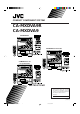
COMPACT COMPONENT SYSTEM CA-MXDVA9R CA-MXDVA9 CA-MXDVA9R CA-MXDVA9 for Australia CA-MXDVA9 for all except Australia INSTRUCTIONS For Customer Use: Enter below the Model No. and Serial No. which are located either on the rear, bottom or side of the cabinet. Retain this information for future reference. Model No. Serial No. GVT0057-008A [A, B, UJ] CA-MXDVA9&9R[A,B,UJ]COVER_1 1 01.8.
Warnings, Cautions and Others IMPORTANT for the U.K. IMPORTANT FOR LASER PRODUCTS DO NOT cut off the mains plug from this equipment. If the plug fitted is not suitable for the power points in your home or the cable is too short to reach a power point, then obtain an appropriate safety approved extension lead or consult your dealer. REPRODUCTION OF LABELS 1 CLASSIFICATION LABEL, PLACED ON REAR ENCLOSURE BE SURE to replace the fuse only with an identical approved type, as originally fitted.
SAFETY INSTRUCTIONS “SOME DOS AND DON’TS ON THE SAFE USE OF EQUIPMENT” This equipment has been designed and manufactured to meet international safety standards but, like any electrical equipment, care must be taken if you are to obtain the best results and safety is to be assured. ✮✮✮✮✮✮✮✮✮✮✮✮✮✮✮✮✮✮✮✮✮✮✮✮✮✮✮✮✮✮✮✮✮✮✮✮✮✮✮✮✮✮✮✮✮✮✮ Do read the operating instructions before you attempt to use the equipment.
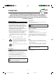
Introduction We would like to thank you for purchasing one of our JVC products. Before operating this unit, read this manual carefully and thoroughly to obtain the best possible performance from your unit, and retain this manual for future reference. About This Manual Power sources This manual is organized as follows: • When unplugging from the wall outlet, always pull the plug, not the AC power cord. • The manual mainly explains operations using the buttons and controls on the unit.
Contents Location of the Buttons and Controls ....................... 3 Selecting Playback Modes ........................................ 25 Front Panel ................................................................. 3 Remote Control .......................................................... 5 Programming the Playing Order of the Titles and Tracks—Program Play ....................................... Playing at Random—Random Play ......................... Repeating Playback .............................
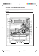
Location of the Buttons and Controls Become familiar with the buttons and controls on your unit. Front Panel Front Panel 1 2 3 4 ; a 5 s 6 d f g 7 8 9 p q w e / r z t y u x i c o v h j k l –3– EN01-10.CA-MXDVA9&9R[A,B,UJ]_1 3 01.8.
Continued Display Window 1 2 34 5 6 7 8 9 p q w e See pages in the parentheses for details. Front Panel 1 Disc trays 2 STANDBY/ON button and STANDBY lamp (11, 12, 43, 44) 3 Remote sensor 4 ECO button (11): Only for England and Australia 5 PRESET + / – control (15) 4 / ¢ (reverse search/forward search) control (11, 14, 21, 22, 25, 27, 35, 42 – 44) 6 Display window 7 TAPE 2 3 button and lamp (12, 31, 33, 34) Pressing this button also turns on the unit.
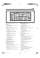
Remote Control Remote Control y u i o 1 2 3 4 5 ; a s 6 7 8 9 p q w e d f g h j r t When using the remote control, point it at the remote sensor on the front panel. 1 FM/AM button (12, 15) Pressing this button also turns on the unit. FM MODE button* (15) 2 AUX button (12) Pressing this button also turns on the unit.
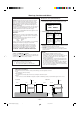
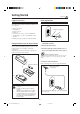
Getting Started Continued Supplied Accessories Connecting Antennas Make sure that you have all the following items. The number in the parentheses indicates the quantity of the pieces supplied.
Connecting Speakers AM antenna IMPORTANT: Use only speakers with the same speaker impedance as indicated by the speaker terminals on the rear of the unit.
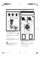
Continued To connect a center speaker and rear speakers By connecting a center speaker and rear speakers to the SURROUND SPEAKERS jacks, you can enjoy Dolby Digital and MPEG multichannel sound, and the DSP Surround modes. (See page 32.
To connect audio equipment with an optical digital input terminal—such as digital decoder To connect a TV You can connect a digital decoder such as an MD recorder or a CD recorder by using an optical digital cord (not supplied). • See also “About sounds output through the rear terminals.” Protective plug OPTICAL DIGITAL OUTPUT PCM / STREAM For CA-MXDVA9R: Connect your TV to the AV OUT terminal using a SCART cable (not supplied). Set the Y/C-COMP.
For CA-MXDVA9: Connect your TV and this unit using the composite video cord (supplied) or an S-video cord (not supplied). • You can also use JVC’s AV COMPU LINK control system. (See page 46.) VIDEO OUT Now, you can plug the AC power cord. When connecting the AC power cord into a wall outlet, the unit automatically starts display demonstration. • Only for CA-MXDVA9 except Australia: If the wall outlet does not match the AC plug, use the supplied AC plug adaptor.
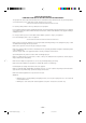
Common Operations Turning On or Off the Power To turn on the unit, press STANDBY/ON so that the STANDBY lamp goes off. Setting the Clock STANDBY/ON STANDBY Before operating the unit any further, first set the clock built in this unit. You can set the clock whether the unit is on or off. On the unit ONLY: 1 Press CLOCK/TIMER. To turn off the unit (on standby), press STANDBY/ON again so that the STANDBY lamp lights up. • The clock appears on the display (if Ecology Mode is not activated).
Continued Setting the AM Tuner Interval Spacing Adjusting the Volume Only for CA-MXDVA9 except Australia: Some countries space AM stations 9 kHz apart, and some countries use 10 kHz spacing. • When shipped, the unit is set to 10 kHz interval. You can adjust the volume level only while the unit is turned on. The volume level can be adjusted in 32 steps (VOL MIN, VOL 01—VOL 30, and VOL MAX). Turn VOLUME + / – clockwise (+) to increase the volume or counterclockwise (–) to decrease it.
Reinforcing the Bass Sound You can select one of the 4 subwoofer levels. This function only affects the playback sound, but does not affect your recording. The subwoofer level can be adjusted in 4 steps— LEVEL 1, LEVEL 2, LEVEL 3, and LEVEL 4 (MAX LEVEL). Turn SUBWOOFER LEVEL + / – clockwise (+) to increase the subwoofer level or counterclockwise (–) to decrease it. When using the remote control, press LEVEL SELECT until “LEVEL” appears. • Press LEVEL + to increase the subwoofer level.
4 Press SET again. Creating Your Own Sound Modes —Manual Mode You can create SEA patterns to suit your preference. These changed settings can be stored in the MANUAL 1, MANUAL 2, and MANUAL 3 modes. • There is a time limit in doing the following steps. If the setting is canceled before you finish, start from step 1 again. 5 Turn 4 / ¢ to select one On the unit ONLY: of the MANUAL 1, MANUAL 2, and MANUAL 3 modes into which you want to store the SEA pattern. 1 Select one of the preset sound modes.
Listening to FM and AM Broadcasts Tuning into a Station On the unit ONLY: 1 Tune into the station you want to preset. 1 Press FM/AM. • See “Tuning into a Station.” The unit automatically turns on and tunes into the previously received station (either FM or AM). • Each time you press the button, the band alternates between FM and AM. 2 Press SET. 2 Start searching for stations. On the unit: Press and hold TUNING + or – for more than 1 second.
Receiving FM Stations with RDS —Only for CA-MXDVA9R RDS (Radio Data System) allows FM stations to send an additional signal along with their regular program signals. For example, the stations send their station names, as well as information about what type of program they broadcast, such as sports or music, etc. To search for a program using the PTY codes REMEMBER you must preset FM RDS stations to use the PTY codes. If not yet done, see page 15. • There is a time limit in doing the following steps.
Switching to a Program Type of Your Choice Temporarily How the EON function actually works: By receiving EON (Enhanced Other Networks) data sent by FM RDS stations, the EON function allows the unit to switch temporarily to a broadcast program of your choice (TA, NEWS, or INFO) from a different station. • The EON function only works when you are listening to a preset FM RDS stations providing EON data. • The EON indicator lights while receiving a station with the EON data.
Playing Back Discs—Introduction Discs you can play This unit has been designed to play back discs having the marks listed below. Disc Type Mark (Logo) Video Format If “ ” appears on the screen when pressing a button, the disc cannot accept an operation you have tried to do. Region Code Number* England: 2 England: PAL Australia: 4 Australia: PAL Others: NTSC Others: 1 or ALL DVD VIDEO Disc Structure DVD A DVD disc consists of Titles, and each title may be divided into some Chapters.
DVD Features Selecting the Audio Language Some DVDs contain several multi-angle views, audio languages and subtitles. When you find the following marks on the DVD or its package, you can select these elements recorded on the DVD. While playing a disc containing audio languages (sound tracks), you can also select the language (sound) to listen to. • You can set your favorite audio language as the initial audio language. (See page 37.) Multi-angle views are recorded on the disc.
Basic Disc Playback Continued This unit cannot accept any disc operations while reading disc contents. Loading Discs * When only 2 VCDs or CDs are loaded, they are played in the same order, but the disc tray without a disc is skipped. On the unit ONLY: 1 Press 0 for the disc tray * This function cannot be used for VCD with the PBC function and DVD. (DVD1, DVD2, or DVD3) you want to load a disc onto. The unit automatically turns on and the disc tray comes out.
To use Time Search and Chapter Search on the TV screen While playing back a disc encoded with Dolby Digital, the DOLBY DIGITAL lamp on the front panel lights up. If it has multichannel signals—5.1ch, the Surround mode is automatically activated. While playing back an MPEG Multichannel disc, the Surround mode is automatically activated. • You cannot use this function while using Random play. On the remote control ONLY: • Using the on-screen menus, you can adjust the speaker settings for 5.
Continued DISC 3 TITLE To stop playing, press 7. • This unit can memorize the stop point of VCD, and when you start VCD playback again by pressing DVD 3¥8 (or DVD 3 on the remote control), playback starts from where it has been stopped—Resume play. When using Resume play on VCD with the PBC function, the playback starts from the earlier point you stop. To use Resume play, you need to turn on the Resume function. (See page 40.) • To stop completely, press 7 twice. 3 CHAP. 2 TIME 1:33:33 BITRATE 3.
3 Reverse Search Enter desired playing time by pressing the number buttons. • You can only use Time Search within a currently playing track. Ex.: To enter the time of “03:45,” press 0, 3, 4 and 5. (Always enter all 4 digits.) To fast-reverse the chapter or track, press 1 while playing a disc. • Each time you press the button, the search speed changes as follows: To cancel misentry for Time Search, press CONTROL −. Each time you press the button the last number you entered is erased.
Menu-Driven Playback—DVD/VCD with PBC Function Menu Operations To cancel the PBC function Menu-driven playback is possible while playing back a DVD with menu-driven features or a VCD with the Playback Control (PBC) function. 7 When playing a DVD DVD discs generally have their own menus or title lists. A menu usually contains various information about the disc and playback selections. On the other hand, a title list usually contains titles of movies and of songs recorded.
Selecting Playback Modes This unit cannot accept any disc operations while reading disc contents. 4 Turn 4 / ¢ to select a title or track number, then press SET. Programming the Playing Order of the Titles and Tracks—Program Play You can arrange the order in which the titles (for DVD) and tracks (for VCD and CD) play before you start playing. You can program up to 18 steps. • When you use Program play for a VCD with the PBC function activated, the PBC function is turned off.
Continued On the remote control: 6 To program another title or track from the 1 Load discs. same disc, repeat step 5. To program another title or track from a different disc, repeat steps 4 and 5. • If the current playing source is not the DVD/VCD/CD player press DVD 3, then 7 before going to the next step. • Each time you select a title or track, the program item is added up to 18 steps. 2 Press PLAY MODE. The play mode screen appears on the TV.
Playing at Random—Random Play The titles and tracks of all loaded discs are played at random. • When you use Random play for a VCD with the PBC function activated, the PBC function is turned off. • Random Play cannot be used on some DVD discs. On the unit: 1 Load discs. • If the current playing source is not the DVD/VCD/CD player, press DVD 3¥8, then 7 before going to the next step. 2 Press RANDOM so that “RANDOM” To stop playing, press 7.
A-B Repeat When DVD is a playing source. While playing, you can also select a portion you want to repeat. • During Program play, Random play or Repeat play A-B Repeat play cannot be selected. • A-B Repeat is not performed between different chapters or different titles on a DVD. REPEAT A-B REPEAT TIME SEARCH CHAP. SEARCH REPEAT CHAPTER TITLE Canceled CHAPTER On the remote control ONLY: • TITLE: Current title will be repeated. • CHAPTER: Current chapter will be repeated.
DVD/VCD Special Effect Playback Still Picture/Frame-by-Frame Playback Slow Motion Playback—Slow You can still a picture and advance the still picture frame by frame. You can enjoy slow motion playback. • Reverse slow motion playback cannot be used on some VCDs. Still picture On the remote control ONLY: On the remote control ONLY: Press 8 once during play. 1 Press 8 once during play. A still picture appears on the TV screen. A still picture appears on the TV screen.
Viewing the Desired Chapters/Tracks—Digest You can view 9 opening scenes of chapters or tracks at a time and select desired scene from those displayed on the TV screen directly. • You cannot use this function on VCD with the PBC function. On the remote control ONLY: 1 Press DIGEST while holding down SHIFT when the disc is stopped playing or during play back. + The opening scene appears in sequence (up to 9 pictures at a time) on the TV screen.
Playing Back Tapes You can play back type I, type II, and type IV tapes without changing any settings. Playing Back a Tape To play both sides repeatedly—Reverse Mode Reverse Mode works for both decks at the same time. When it is in use, the tape automatically reverses at the end of a side and the unit starts playing for the other side of the tape, and repeats the same process. To use Reverse Mode, press REVERSE MODE so that the Reverse Mode indicator on the display lights up like— .
Using DSP Surround Mode 3 Press LEVEL + / – to adjust the In order to reproduce a more acoustic sound field in your listening room while playing any source, you can use following DSP Surround modes. • DSP Surround mode can be also used for a disc encoded with Dolby Digital 5.1ch and with MPEG Multichannel. delay time. • Each time you press the button, the delay time changes as follows: You can select one of the following DSP Surround modes according to your preference.
Recording Recording a Tape on Deck B IMPORTANT: • It should be noted that it may be unlawful to re-record pre-recorded tapes, records, or discs without the consent of the owner of copyright in the sound or video recording, broadcast or cable programme and in any literary, dramatic, musical, or artistic embodied therein. • The recording level is automatically set correctly, so it is not affected by the VOLUME, the SUBWOOFER LEVEL, the SOUND MODE, and the DSP Surround controls.
Continued Dubbing Tapes VCD/CD Direct Recording You can record from one tape to another. You can easily record sound of a VCD without the PBC function or CD onto a tape. • You can also record the tracks in order you have made the program. • This function cannot be used for recording DVDs. On the unit ONLY: 1 Press TAPE 2 3, then 7. On the unit ONLY: 1 Put a recordable cassette into deck B. 2 Load discs with the label side up.
Auto Edit Recording 4 Press SET. • Each time you press the button, the tracks to be recorded on the front side (“SIDE-A”) and on the reverse side (“SIDE-B”) alternate. By using Auto Edit Recording, you can record disc tracks to fit the tape. Auto Edit Recording makes a program by selecting disc tracks in numerical order. However, to prevent the end of the last track on the front side from being cut off, the last track is selected so as to fit on the remaining tape length.
Operating the On-Screen Menu Continued Using the on-screen menus, you can store the initial selection for subtitle languages and audio languages (sound) for DVD playback as well as other settings. • The on-screen menu disappears if no operation is done for five minutes.
Changing the Initial Language Settings On LANGUAGE menu, you can select the following initial languages. MENU LANGUAGE ENGLISH AUDIO LANGUAGE ENGLISH SUBTITLE ENGLISH ON SCREEN LANGUAGE ENGLISH EXIT PRESS KEY • MENU LANGUAGE :Select the DVD menu language. Selectable languages—ENGLISH, SPANISH, FRENCH, CHINESE, GERMAN, ITALIAN, JAPANESE, AA – ZU (Language code: see page 51.) • AUDIO LANGUAGE :Select the initial language for audio sound language.
Continued More about “SPEAKER SETTING” “EXPERT” adjustment procedure The following example shows the ideal speaker locations for surround reproduction in your listening room. 7 Adjusting the delay time for the center and rear speakers You can adjust the delay time of the sounds from the center speaker and from the rear speakers, comparing to that of the sound from the front speakers.
7 Adjusting the center and rear speaker output levels You can adjust the speaker output level for the center speaker and rear speakers. You can adjust the output level while listening to the test tone. • Make adjustments so that the sound level of the selected speaker is set at the same level as that of the front speakers. • To output test tone properly, turn off the sound mode and the DSP Surround mode before entering on-screen menu. 1 Display EXPERT SPEAKER SETTING menu. • See page 36.
7 Monitor types Changing the System Settings • 4:3 LB (Letter Box) : Select this when viewing on TV whose aspect ratio is 4:3. While viewing a wide screen picture, the black bars appear on the top and the bottom of the screen. On SYSTEM menu, you can change the following settings. AUTO STANDBY RESUME OFF AV COMPULINK MODE • 16:9 WIDE: Select this when viewing on TV whose aspect ratio is 16:9.
Using the Parental Lock Setting the Parental Lock Level 6 Press ENTER. The parental lock level is set and PARENTAL LOCK screen disappears from the TV. Using this function, you can restrict playback of DVD containing violent scenes (and those not suitable for your family members). • This function is only possible for the DVDs containing such rating level information (Level 1 to Level 8). To exit from PARENTAL LOCK screen any time during the above procedure, press ENTER while holding down 7.
Using the Timers Continued On the unit ONLY: There are three timers available—Daily Timer, Recording Timer, and Sleep Timer. Before using the timers, you need to set the clock built in the unit. (See page 11.) 1 Press CLOCK/TIMER repeatedly until “DAILY” appears on the display. indicator lights up and DAILY (Daily Timer) indicator also starts flashing on the display. Using Daily Timer With Daily Timer, you can wake to your favorite music or radio program.
5 Turn 4 / ¢ to select the source to play, 9 Press STANDBY/ON to turn off the unit (on standby) if you have set the Daily Timer with the unit turned on. then press SET. • The source changes as follows: TUNER FM AUX TUNER AM TAPE 6 When selecting “TUNER FM” or “TUNER Turn 4 / ¢ to select the preset station number, then press SET. The unit enters volume setting mode. When selecting “DISC– – –” 1) Turn 4 / ¢ to select the disc number, then press SET.
Continued 4 Set the on-time you want the Using Recording Timer unit to turn on at. With Recording Timer, you can make a tape of a radio broadcast automatically. You can set the timer whether the system is on or off. 1) Turn 4 / ¢ to set the hour, then press SET. 2) Turn 4 / ¢ to set the minute, then press SET. “OFF TIME” appears for 2 seconds on the display, then the unit enters off-time setting mode.
To turn off or on Recording Timer after its setting is done Timer Priority 1 Press CLOCK/TIMER repeatedly until “REC” appears on the display. Since each timer can be set separately, you may wonder what happens if the setting for these timers overlaps. Here are examples. 2 To turn off the Recording Timer, press CANCEL/DEMO. indicator and the REC (Recording Timer) indicator go off from the display (“OFF” appears for a while).
Using AV COMPU LINK Control System The AV COMPU LINK control system allows you to use JVC’s TV with simple operations. To use AV COMPU LINK control system, you need to connect this unit and a TV through the AV COMPU LINK terminals. • You can connect a TV that has AV COMPU LINK II or AV COMPU LINK EX terminals. AV COMPU LINK Connection Connect a TV by using a SCART cable or video cord (see pages 9 and 10) then also connect it by using a cord with monaural mini-plugs (not supplied).
Appendix A—Maintenance To get the best performance of the unit, keep your discs, tapes, and mechanism clean. Handling discs Handling cassette tapes • Remove the disc from its case by holding it at the edge while pressing the center hole lightly. • Do not touch the shiny surface of the disc, or bend the disc. • Put the disc back in its case after use to prevent warping. • If the tape is loose in its cassette, take up the slack by inserting a pencil in one of the reels and rotating.
Appendix B—Troubleshooting If you are having a problem with your unit, check this list for a possible solution before calling for service. If you cannot solve the problem from the hints given here, or the unit has been physically damaged, call a qualified person, such as your dealer, for service. Symptom Cause Action Unable to cancel the display demonstration. Other buttons are pressed to cancel the display demonstration. Press CANCEL/DEMO on the unit. (See page 10.) No sound is heard.
Appendix C—Description of the PTY Codes NEWS: News. FINANCE: AFFAIRS: Topical program expanding or enlarging upon the news — debate, or analysis. CHILDREN: Programs targeted at a young audience. INFO: Program the purpose of which is to impart advice in the widest sense. RELIGION: Religious programs. SPORT: Program concerned with any aspect of sports. PHONE IN: EDUCATE: Educational programs. Involving members of the public expressing their views either by phone or at a public forum.
Appendix E—Channel Display Current outputting channel appears on the display when you press DISPLAY. (See page 19.) Linear PCM and DTS DOLBY DIGITAL Display LFE 1/0 CH 1/0.1 CH ON 2/0 CH 2/0.1 CH ON 2/0 CH 2/0.1 CH ON 2/0 CH 2/0.1 CH ON 3/0 CH 3/0.1 CH ON ON ON 2/2 CH 2/2.1 CH ON 3/2 CH 3/2.
Appendix F—Language Code for On-Screen Menu This code list is used when you select a language of on-screen menus. (See page 37.
Appendix G—Country Code for Parental Lock Continued This code list is used when you set a country code for parental lock. (See page 41.
Code Country Code Country Code Country LI Liechtenstein PE Peru TJ Tajikistan LK Sri Lanka PF French Polynesia TK Tokelau LR Liberia PG Papua New Guinea TM Turkmenistan LS Lesotho PH Philippines TN Tunisia LT Lithuania PK Pakistan TO Tonga LU Luxembourg PL Poland TP East Timor LV Latvia PM Saint Pierre and TR Turkey LY Libyan Arab Jamahiriya Miquelon TT Trinidad and Tobago MA Morocco PN Pitcairn TV Tuvalu MC Monaco PR Puerto Rico TW Taiwan MD
Specifications Continued CA-MXDVA9R Output Power (IEC 268-3/DIN) FRONT SUBWOOFERS: 80 W per channel, min. RMS, driven into 6 Ω at 63 Hz with no more than 10% total harmonic distortion. FRONT MAIN SPEAKERS: 40 W per channel, min. RMS, driven into 6 Ω at 1 kHz with no more than 10% total harmonic distortion. SURROUND (REAR and CENTER) SPEAKERS: 20 W per channel, min. RMS, driven into 16 Ω at 1 kHz with no more than 10% total harmonic distortion.
CA-MXDVA9 for Australia Output Power (IEC 268-3/DIN) FRONT SUBWOOFERS: 80 W per channel, min. RMS, driven into 6 Ω at 63 Hz with no more than 10% total harmonic distortion. FRONT MAIN SPEAKERS: 40 W per channel, min. RMS, driven into 6 Ω at 1 kHz with no more than 10% total harmonic distortion. SURROUND (REAR and CENTER) SPEAKERS: 20 W per channel, min. RMS, driven into 16 Ω at 1 kHz with no more than 10% total harmonic distortion.
CA-MXDVA9 except Australia Output Power FRONT SUBWOOFERS: 90 W per channel, min. RMS, driven into 6 Ω at 63 Hz with no more than 10% total harmonic distortion. FRONT MAIN SPEAKERS: 45 W per channel, min. RMS, driven into 6 Ω at 1 kHz with no more than 10% total harmonic distortion. SURROUND (REAR and CENTER) SPEAKERS: 25 W per channel, min. RMS, driven into 16 Ω at 1 kHz with no more than 10% total harmonic distortion.
Mains (AC) Line Instruction (not applicable for Europe, U.S.A., Canada, Australia, and U.K.) ANTENNA VOLTAGE SELECTOR AM EXT AM LOOP 230V 240V FM 75 220V COAXIAL VIDEO OUT VIDEO 127V S-VIDEO 110V OPTICAL DIGITAL OUTPUT SURROUND SPEAKERS SUBWOOFER REAR CENTER 5.
INSTRUCTIONS SPEAKER SYSTEM SP-MXDVA9R BEDIENUNGSANLEITUNG: LAUTSPRECHERSYSTEM MANUEL D’INSTRUCTIONS: SYSTEME DES ENCEINTES GEBRUIKSAANWIJZING: LUIDSPREKERSYSTEEM MANUAL DE INSTRUCCIONES: SISTEMA DE ALTAVOCES ISTRUZIONI: SISTEMA DI ALTOPARLANTI BRUKSANVISNING: HÖGTALARSYSTEM VEJLEDNING: HØJTTALERSYSTEM KÄYTTÖOHJE: KAIUTINJÄRJESTELMÄ This system consists of the following systems: Dieses System besteht aus den folgenden Systemen: Cette chaîne comprend les enceintes suivantes: Dit systeem bestaat uit de vo
Thank you for purchasing JVC speakers. Before you begin using them, please read the instructions carefully to be sure you get the best possible performance. If you have any questions, consult your JVC dealer. Grazie per aver acquistato questi altoparlanti della JVC. Prima di cominciare l’uso degli altoparlanti, leggete attentamente le istruzioni per assicurare le migliori prestazioni. Qualora sorgessero dei dubbi, rivolgetevi al vostro rivenditore JVC. Vielen Dank für den Kauf dieser JVC-Lautsprecher.
FRONT SPEAKER SYSTEM : SP-MXG79 FRONTLAUTSPRECHERSYSTEM : SP-MXG79 SISTEMA DIFFUSORI ANTERIORI : SP-MXG79 ENCEINTES AVANT: SP-MXG79 FRÄMRE HÖGTALARE : SP-MXG79 VOORLUIDSPREKERSYSTEEM : SP-MXG79 FRONTHØJTTALERSYSTEM : SP-MXG79 SISTEMA DE ALTAVOCES DELANTEROS : SP-MXG79 ETUKAIUTTIMET : SP-MXG79 SPEAKER FOR A/V COMBINATION HAUT-PARLEURS POUR COMBINAISON A/V SP-MXG79 have magnetically-shielded design for placement adjacent to TVs and monitors without causing color aberrations.
LUIDSPREKER VOOR A/V KOMBINATIE ALTAVOZ PARA COMBINACIÓN A/V De SP-MXG79 is magnetisch afgeschermd zodat deze in de buurt van een TV en monitor kan worden geplaatst en hierbij de kleuren op het scherm van deze toestellen niet door de luidspreker worden aangetast. Indien de luidspreker echter op een verkeerde wijze wordt geãnstalleerd, worden de kleuren mogelijk wel aangetast. Let daarom op het volgende: 1.
Connection Anschluß Raccordement Aansluiting Conexión Collegamento Ansluiting Tilslutning Liitäntä CONNECTION Right speaker Rechter Lautsprecher Enceinte de droite Rechter spreker Altavoz derecho Altoparlante destro Höger högtalare Højre højttaler Oikea kaiutin RED ROT ROUGE ROOD ROJO ROSSO RÖD RØD PUNAINEN BLACK SCHWARZ NOIR ZWART NEGRO NERO SVART SORT MUSTA BLUE BLAU BLEU BLAUW AZUL BLU BLA BLA SININEN • DON’T use other amplifier to operate this speaker system except for CA-MXDVA9R.
ANSCHLUSS RACCORDEMENT • Verwenden Sie zum Betrieb dieses Lautsprechersystems keinen anderen Verstärker, ausgenommen CA-MXDVA9R. • Schalten Sie vor dem Anschluß der Lautsprecher an den Verstärker die Spannungsversorgung des gesamten Systems aus. • Der Hauptlautsprecher des Modells SP-MXDVA9R kann maximal eine Leistung von 55 W handhaben, während der vordere Subwoofer maximal 110 W handhaben kann. Eine Überlastung führt zu Verzerrungen und möglicherweise zu Beschädigungen.
AANSLUITINGEN CONEXIÓN • Gebruik GEEN andere versterker dan de CA-MXDVA9R om dit luidsprekersysteem aan te sturen. • Schakel de spanning van alle aangesloten komponenten uit alvorens de luidsprekers met de versterker te verbinden. • Het maximaal te verwerken ingangsver mogen van de SP-MXDVA9R hoofd-luidspreker is 55 W, van de voor-subwoofer 110 W. Te hoge ingang kan in abnormale geluidsreproduktie en in beschadigingen resulteren.
COLLEGAMENTO ANSLUTNING • NON usare un amplificatore diverso dal modello CA-MXDVA9R per utilizzare questo sistema di altoparlanti. • Spegnete la corrente dell’intero sistema prima di collegare gli altoparlanti all’amplificatore. • La potenza massima sostenibile dall’altoparlante principale del SP-MXDVA9R è 55 W, quella del Subwoofer anteriore è 110 W. Un ingresso eccessivo causerà un suono anormale è possibili danni.
TILSLUTNING LIITÄNTÄ • Anvend IKKE anden forstærker end CA-MXDVA9R til drift af dette højttalersystem. • Sluk for strømmen til hele systemet før højttalerne forbindes til forstærkeren. • Maksimal belastningsevne for SP-MXDVA9R hovedhøjttaleren er 55 W, mens den er 110 W for front-subwooferen. For kraftigt indgangssignal vil resultere i unormal stoj og muligvis beskadigelse.
CENTER & SURROUND SPEAKER SYSTEM SISTEMA DIFFUSORE CENTRALE : SP-DSC99TN SISTEMA DIFFUSORI SURROUND : SP-DSS99TN MITTHÖGTALARE : SP-DSC99TN SURRONDHÖGTALARE : SP-DSS99TN CENTERHØJTTALERSYSTEM : SP-DSC99TN SURROUNDHØTTALERSYSTEM : SP-DSS99TN KESKIKAIUTIN : SP-DSC99TN YMPÄRISTÖTILAKAIUTTIMET : SP-DSS99TN CENTER SPEAKER SYSTEM : SP-DSC99TN SURROUND SPEAKER SYSTEM : SP-DSS99TN MITTENLAUTSPRECHERSYSTEM : SP-DSC99TN RUNDUMLAUTSPRECHERSYSTEM : SP-DSS99TN ENCEINTE CENTRALE : SP-DSC99TN ENCEINTES SURROUND : SP-DSS9
ALTAVOZ PARA COMBINACIÓN A/V El modelo SP-DSC99TN tiene una construcción protegida magneticamente para una colocación contigua de los televisores y monitores sin causar aberraciones de color. Sin embargo, el color puede ser afectado como resultado del modo de instalar el sistema de altavoces. 1. Al colocar los altavoces cerca de un televisor, desactivar el interruptor de alimentación principal del televisor o desconectarlo antes de instalar los altavoces.
Amplifier connection Verstärkeranschluß Raccordement à l'amplificateur Aansulaiten op de versterker Anslutning till en förstärkare Conexión al amplificador Collegamento dell'amplificatore Forstærkertilslutning Vahvistimen liitäntä CONNECTION Center speaker Mittenlautsprecher Enceinte centrale Middenluidspreker Altavoz central Diffusore centrale Mitthögtalare Centerhøjttaler Keskikaiutin Amplifier output terminals Ausgang des Verstärkers Bornes de sortie de l'amplificaterur Uitgangsaansluitengen van de v
ANSCHLUSS RACCORDEMENT Das Ende der Lautsprecherleitung ist mit einem Stifstecker ausgerüstet. Ist die Lautsprecheranschlußlemme des Verstärkers, woran der Lautsprecher angeschlossen wird, mit einer Anschlußbüchse ausgerüstet, dann wird die Leitung des linken Lautsprechers an die Anschiußklemme Links und der rechte Lautsprecher an die Anschlußklemme Rechts angeschlossen. • Alle Geräte der Anlage ausschalten, bevor die Boxen an den Verstärker angeschlossen werden.
AANSLUITINGEN CONEXIÓN Een pinstekker is bevestigd aan het uiteinde van het luidsprekerssnoer. Indien de aansluiting voor de luidspreker op de verterker aan welke de luidspreker op de links aansluiting, en de draad van de rechtse luidspreker op de rechts aansluiting aan. • Schakel de spanning van alle apparatuur uit alvorens de luidspreker met de versterker te verbinden. • De nominale impedantie van de SP-DSC99TN bedraagt 16 Ω. Sluit de luidsprekers aan’op een versterker met een laadimpedantie van 16 Ω.
COLLEGAMENTO ANSLUTNING Uno spinotto a spillo viene fissato all’estremità del cordone degli altoparlanti. Se il morsetto di collegamento degli altoparlanti sull’amplificatore al quale è collegato l’altoparlante è un jack a spillo, collegare il filo dell’altoparlante della sinistra al morsetto di sinistra, e il filo dell’altoparlante della destra, al morsetto di destra. • Disattivare l’alimentazione di tutta l’attezzatura prima di collegare l’altoparlante all’amplificatore.
TILSLUTNING LIITÄNTÄ Der sidder en stikpropp for enden af højttalerkablet. Hvis højttaleren skal tilsluttes, er en stik-jack, skal den venstre højttalers kabel sættes i den venstre klemterminal og den højre højttalers kabel i den højre klemterminal. • Sluk for strømmen i al udrustningen før højttalerne tilsluttes forstærkeren. • Den nominelle impedans for SP-DSC99TN er 16 Ω. Tilslut dem til en forstærker med en belastningsimpedans for 16 Ω højttaler. • Den nominelle impedans for SP-DSS99TN er 16 Ω.
NOTICE Display Demonstration When connecting the AC power cord into a wall outlet, the unit automatically starts display demonstration. To cancel the display demonstration, press CANCEL/DEMO until “DEMO OFF” appears on the display. • For more detailed information about demonstration, see page 10. GV40261-006A [A, B, UJ] CA-MXDVA9[A,B,UJ]SHEET(demo)f 1 01.8.