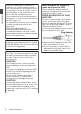
. 4K MEMORY CARD CAMERA RECORDER GY-HM250U/GY-HM250E GY-HM180U/GY-HM180E GY-HM170U/GY-HM170E GY-HM250U(G)/GY-HM250E(G) GY-HM180U(G)/GY-HM180E(G) GY-HM170U(G)/GY-HM170E(G) INSTRUCTIONS . The illustration here shows how the handle unit is attached using the unit supplied. The specifications and appearance of this product are subject to changes for further improvement without prior notice. Please check the latest version of the INSTRUCTIONS from the following Mobile User Guide.
FOR USA These are general IMPORTANT SAFEGUARDS and certain items may not apply to all appliances. IMPORTANT SAFEGUARDS 8. 9. 10. 11. 12. 13. Introduction 1. 2. 3. 4. 5. 6. 7. Read these instructions. Keep these instructions. Heed all warnings. Follow all instructions. Do not use this apparatus near water. Clean only with dry cloth. Do not block any ventilation openings. Install in accordance with the manufacturer’s instructions.
Safety Precautions This device complies with Part 15 of FCC Rules. Operation is subject to the following two conditions: (1) This device may not cause harmful interference, and (2) this device must accept any interference received, including interference that may cause undesired operation. FOR USA AND CANADA Introduction CAUTION RISK OF ELECTRIC SHOCK DO NOT OPEN Changes or modifications not approved by JVC could void the user’s authority to operate the equipment.
WARNING: TO PREVENT FIRE OR SHOCK HAZARD, DO NOT EXPOSE THIS UNIT TO RAIN OR MOISTURE. POUR CANADA ATTENTION AVERTISSEMENT : POUR EVITER LES RISQUES D’INCENDIE OU D’ELECTROCUTION, NE PAS EXPOSER L’APPAREIL A LA PLUIE NI A L’HUMIDITE. ATTENTION: POUR EVITER TOUT RISQUE D’ELECTROCUTION NE PAS OUVRIR LE BOITER. AUCUNE PIECE INTERIEURE N’EST A REGLER PAR L’UTILISATEUR. SE REFERER A UN AGENT QUALIFIE EN CAS DE PROBLEME.
Introduction When the equipment is installed in a cabinet or on a shelf, make sure that it has sufficient space on all sides to allow for ventilation (10 cm (3-15/16") or more on both sides, on top and at the rear). Do not block the ventilation holes. (If the ventilation holes are blocked by a newspaper, or cloth etc. the heat may not be able to get out.) No naked flame sources, such as lighted candles, should be placed on the apparatus.
IMPORTANT (for owners in the U.K.) Connection to the mains supply in the United Kingdom. DO NOT cut off the mains plug from this equipment. This equipment is in conformity with the provisions and protection requirements of the corresponding European Directives. This equipment is designed for professional video appliances and can be used in the following environments: Controlled EMC environment (for example, purpose-built broadcasting or recording studio), and rural outdoors environments.
Introduction Dear Customer Battery Pack This apparatus is in conformance with the valid European directives and standards regarding electromagnetic compatibility and electrical safety. European representative of JVCKENWOOD Corporation is: JVCKENWOOD Deutschland GmbH Konrad-Adenauer-Allee 1-11 61118 Bad Vilbel GERMANY The supplied battery pack is a lithium-ion battery.
o Para Brasil Introduction Informação sobre eliminação de baterias Este produto não deverá ser eliminado como lixo doméstico em geral. Devolva a bateria velha ao comerciante ou para a rede autorizada, para que seja devolvida ao fabricante ou importador. A reciclagem e eliminação de lixo em uma maneira adequada, ajudarão para preservar recursos, prevenindo, ao mesmo tempo, contra efeitos prejudiciais sobre a nossa saúde e o meio ambiente. .
Contents Introduction Introduction Safety Precautions ............................................ 4 Contents .......................................................... 10 Main Features ................................................. 13 Precautions for Proper Use ............................. 16 Operation Modes ............................................. 20 Names of Parts ................................................ 22 Side Control Panel .......................................
Menu Display and Detailed Settings Display/Status Screen Display Screen in Camera Mode ................... 139 Display Screen in Media Mode ...................... 145 Status Screen ................................................ 147 Camera Features Marker and Safety Zone Displays (Camera Mode Only) .............................................................. 148 Color Bar Output ........................................... 148 Adjusting Color Matrix ...................................
Introduction Broadcast Overlay n ................................. 192 Importing and Configuring Settings for SDP Files for Broadcast ............................................. 192 Displaying Watermark Images ................... 194 Displaying Images on the Whole Screen (Full Screen Graphic Function) .......................... 195 Protecting Overlay Settings with a Password ................................................................... 197 Specifying Text and Images .......................
Main Features Recording and playback at 30p/25p/24p are possible in 4K resolution (3840x2160 pixels), which contains information that is about four times larger than Full HD. And in addition to recording at 150 Mbps for 4K shooting with H.264 codec, this camera recorder also supports a recording mode of 70 Mbps. Videos can also be recorded in Class 10 SDHC/SDXC memory cards.
Color Matrix Adjustment Function Introduction With the detailed settings of the Color Matrix Adjustment, when shooting is performed using multiple cameras, colors in different cameras can be adjusted, and a color of the user’s preference can be set on this camera recorder. The “Setup Files” saved on the SD card can also be used to enable the same setup status for other GY-HM250/GY-HM180/GY-HM170.
Auto focus/Optical and electronic image stabilizer Professional-style switch layout and diverse video parameters Switches for Gain and White Balance are available on the side panel to enable quick switching according to the shooting scene. Image quality parameters such as gamma and color matrix are also available in the menu for adjustment to the preferred tones.
Precautions for Proper Use Storage and Usage Locations Introduction o Allowable ambient temperature and humidity Be sure to use this unit within the allowable temperature range of 0 °C to 40 °C (32 °F to 104°F) and a relative humidity of 30 % to 80 %. Using this unit at a temperature or humidity outside the allowable ranges could result not only in malfunction but also serious impact on the CMOS elements as small white spots may be generated. Please exercise care during use.
Regular Inspection (Maintenance) SDHC/SDXC Cards o SDHC/SDXC card is referred to as SD card in this manual. o This camera recorder saves the recorded images and audio sound on the SD card (sold separately) in the card slot. o If the SD card contains files recorded by devices other than this camera recorder or files that are saved from a PC, the recordable time may be shorter or data may not be properly recorded.
LCD Monitor and Viewfinder Introduction o The LCD monitor and viewfinder screen are manufactured using high-precision technology. Black spots may appear on the LCD monitor and viewfinder screen, or red, blue, and/or white spots may not disappear. However, this is not a malfunction and these spots are not recorded on the SD card. o If you use this unit continuously for a long period of time, the characters displayed in the viewfinder may temporarily remain on the screen.
Others Introduction o Do not insert objects other than the memory card into the card slot. o Do not block the vent on the unit. Blocking of the vent causes internal heating and may lead to burns and fires. o Do not turn off the [POWER ON/OFF] switch or remove the power cable during recording or playback. o The camera recorder may not show stable pictures for a few seconds immediately after the power is turned on, but this is not a malfunction.
Operation Modes This camera recorder has four operation modes - Camera mode, Media mode, USB mode and Remote Edit mode.
Operation Mode Camera Mode Description 0 This is the camera shooting mode. The camera recorder starts up in Camera mode when the power is turned on. 0 Camera images are output on the viewfinder and LCD monitor. When a recordable Media Mode 0 This mode allows you to play back or delete clips recorded on the SD card. 0 When a playable SD card is inserted, the thumbnail or playback screen is displayed on the viewfinder and LCD monitor.
Names of Parts B Introduction J I C D E A F C [MODE] Camera/Media Mode Selection Button (A P20 [Operation Modes] ) D [POWER ON/OFF] Lock Power ON/OFF Switch Turns ON/OFF the power. 0 Hold down the lock button (blue) in the center to toggle ON/OFF. 0 When the power is turning OFF, “P.OFF” appears on the LCD monitor and viewfinder. 0 Wait for 5 seconds or more to turn on the power again.
Side Control Panel E D F B A . G M L K J I H A [FULL AUTO] Full Auto Selection Button Press and hold the button to switch the Full Auto mode ON and OFF. Full Auto mode adjusts the Iris, Gain, Shutter and White Balance automatically.
GY-HM180U/GY-HM180E GY-HM170U/GY-HM170E Side Terminal Section A B Introduction C A B C D D . . A [HOST] USB Host Terminal n For connecting an USB adapter according to the intended purpose when you are connecting the unit to a network.
LCD Monitor D C B A . H I J M L K A LCD Monitor (A P40 [Adjusting the LCD Monitor and Viewfinder] ) B [CANCEL/STOP] Cancel/Stop Button Cancels various settings and stops playback. C LCD Cross-Shaped Button (JKHI)/Set Button (R) 0 The function changes according to the operation status of the camera recorder.
Handle Unit Section B A C D Introduction E F T S R Q M N O P G H I J K L . A Microphone Holder (A P29 [Attaching the External Microphone O] ) B Microphone Holder Lock Knob (A P29 [Attaching the External Microphone O] ) C Handle Tally Lamp (A P42 [Tally Lamp] ) (A P202 [Blinking of the Tally Lamp] ) D Accessory Mounting Screw Hole E Shoe For mounting separately sold lights and accessories.
Lens Section . B C Introduction A D A Filter Built-In Screw 0 Transparent or UV filter for lens protection, or filters for various effects can be installed. 0 Installable filter types: Φ62 mm P0.75 Memo : 0 Remove the lens hood when installing the filter. (A P30 [Attaching/Detaching the Hood] ) B Focus Ring (A P54 [Focus Operation] ) C Zoom Ring (A P53 [Zoom Operation] ) You can set different functions for the zoom ring and iris dial in [Camera Function] B [Zoom Ring].
Basic System Diagram When handle unit is attached Introduction GY-HM250U/GY-HM250E/ GY-HM180U/GY-HM180E/ GY-HM170U/GY-HM170E Microphone Wireless Microphone Receiver Headphone [INPUT1/INPUT2] [x] [AUX] Handle Unit Battery Battery Charger n : IDX Battery Charger n: SSL-JVC50 mM: BN-VC826 [SDI OUT] n m [DC] [HDMI] AC Adapter SDI Cable BNC HDMI Cable [AV] AV Cable Standard Package Monitor RCA pin [HOST] n Network Adapter [REMOTE] Carrying Case Remote Control Unit [DEVICE] USB Cable Tripod
Settings and Adjustments Before Use Adjusting the Grip Belt Open the pad and adjust the position of the grip belt accordingly. Attaching the Handle Unit . Caution : 0 If the grip is loose, the camera recorder may fall off resulting in injuries or malfunction. Attaching the External Microphone O You can attach a separately sold microphone to the microphone holder. 1, 3 . 1 Fit the handle terminal at the bottom of the handle unit to the handle unit mount at the top of the camera recorder.
Attaching/Detaching the Lens Cap 0 Before shooting, detach the lens cap. 0 When this camera recorder is not in use, attach the lens cap to protect the lens. 0 Pinch the tabs on both sides of the lens cap to attach and detach the lens cap. Attaching/Detaching the Hood Attaching the Hood Align the markings on the camera recorder and hood; turn the hood in the direction of the arrow (clockwise) until it is locked. Preparations . Detaching the Hood .
Attaching the Anti-reflective Film Attach the supplied anti-reflective film onto the LCD monitor if necessary, such as when you are recording in the day or outdoors. Doing so helps to cut down reflection of outside light, thus improving the visibility. Use the screw hole at the bottom of this camera recorder. (1/4×20UNC) Use the screw hole that suits the tripod.
Power Supply Preparations To use this camera recorder, you can attach a battery pack or connect an AC adapter to it. (A P32 [Using a Battery Pack] ) (A P34 [Using AC Power (DC IN Power)] ) Caution : 0 Set the [POWER ON/OFF] switch to “OFF” before changing the power supply that operates this camera recorder. 0 To charge the battery using a battery charger, purchase a genuine charger that can charge the recommended battery. n 0 Charge the battery in the camera recorder.
Removing the Battery GY-HM250U/GY-HM250E 2 2 1 . 1 Hold down the lock button (blue) at the center of the [POWER ON/OFF] switch to set to “OFF”. 2 While pressing and holding the [BATT. RELEASE] button, push up and remove the battery in the direction of the arrow. Caution : 0 Do not remove the battery when the [POWER ON/OFF] switch is “ON”. 0 Do not insert or remove the DC cable when the battery is in use.
Using AC Power (DC IN Power) Use the supplied AC adapter to operate the camera recorder with AC power. Power Status Display Viewfinder Screen and LCD Monitor The power status is displayed on the display and menu screens. Preparations Display B 7.4V B 100min C 30% 4 RES Description Currently powered by a battery. When the battery power runs out, the battery mark appears hollow, and “RES” (yellow) is displayed. Memo : 0 You can set the display using [LCD/VF] B [Display Settings] B [Battery].
Menu Screen 0 If the battery is not fully charged, the battery will be charged at the same time. (A P98 [Display and Description of the Menu Screen] ) 0 Even when a fully charged battery is used, charge the battery briefly to confirm the remaining battery power. (A P32 [Power Supply] ) (A P34 [Power Status Display] ) Display Settings Preparations . Warnings by Lamp and Warning Tone Warning status is indicated by tally lamp and warning tone. 0 The tally lamp blinks.
Initial Settings When the power is first turned on, the Initial Setting screen for performing the initial settings in the camera recorder appears. Set the date/time of the built-in clock in the [Initial Setting] screen. All operations are disabled until initial settings are complete. Memo : 0 The menus and messages on the screen of the LCD monitor or viewfinder are displayed in the selected language. 2 Select a language using the cross-shaped button (JK), and press the Set button (R).
4 Press the Set button (R) after confirming the exit screen. The [Initial Setting] screen appears. 0 For U models Initial Setting UTC-05:00 . 0 For E models Setting the Date/Time (A P122 [ Date/Time ] ) 1 Select [System] B [Date/Time]. The [Date/Time] screen appears. 2 Set the date and time. A Move the cursor with the cross-shaped button (HI) and select the setting item. B Change the values with the cross-shaped button (JK). 3 Press the Set button (R) after setting is complete.
Displays on the LCD Monitor and Viewfinder Display Screen (VF/LCD) in Media Mode (A P145 [Display Screen in Media Mode] ) 0 This is the screen display during clip playback in Media Mode. 0 The display switches between three screen Preparations You can display the camera status, media information, zebra pattern, and various markers in the video image on the LCD monitor and viewfinder screen during shooting.
USB Mode Screen Status Screen This screen displays the USB mode. 0 This screen allows you to check the current USB Mode . Remote Edit Mode Screen n This is a mode for accessing the page for editing the metadata that is recorded in a clip via a web browser on devices such as a smartphone, tablet terminal, or PC.
Adjusting the LCD Monitor and Viewfinder Adjusting the LCD Monitor Tilt 90 degrees downward 2 You can monitor video images on this camera recorder using the viewfinder, LCD monitor, or both. Tilt 180 degrees upward Normal LCD Preparations 1 Inverted LCD . .
Adjusting the Viewfinder You can change the brightness and peaking of the viewfinder screen according to your usage conditions. Changing the brightness of the screen will not affect the recorded images. 2 3 . Caution : 0 A high-definition viewfinder is used on this camera recorder in order to provide an accurate focusing environment. Due to the characteristic of the display device, colors may appear on the images when you blink your eyes. This is not a malfunction.
Assignment of Functions to User Buttons You can assign functions to the following buttons and use them as user buttons. By assigning functions to the buttons, the usability of the camera recorder can be enhanced. Perform settings in the menu items corresponding to each button. Preparations Button [F.ASSIST/1] Button [TC/2] Button [LOLUX/3] Button [C.
SD Card o When [System] B [Record Set] B [Record Format] B [Format] is set to “QuickTime” This camera recorder saves the recorded images and audio sound on the SD card (sold separately) in the card slot.
Write-Protect Switch on the SD Card Card Slot Status Indicator A Slide the write-protect switch upward to enable writing or deleting. B Slide the write-protect switch downward to prevent writing or deleting. (Images in the card are protected.) The following table shows the respective states of slot A and B. Write-Protect Switch Preparations A B Write/Delete Enabled Write/Delete Disabled Lamp Lights up in red Slot Status The inserted SD card is being accessed.
Switching the SD cards When both card slots are inserted with SD cards, you can use the [SLOT SEL] button to switch the card to use. When the memory on an SD card is full during recording, data recording automatically switches to the other card. 1 Select [System] B [Media] B [Format Media]. (A P121 [ Format Media ] ) 2 Select the slot of the SD card to be formatted and press the Set button (R). Format Media Format Slot A Format Slot B 2 Preparations Set . .
6 Formatting is complete. 3 Restoring starts. Preparations When formatting is complete, “Complete” appears and the camera recorder returns to the [Format Media] screen. Memo : 0 During formatting, menu operation is unavailable but you can start recording. However, this is only available when a recordable SD card is inserted in the other slot. 0 Formatting cannot be performed in the following cases. 0 Recording is in progress on the SD card to be formatted. 0 SD card is not inserted.
Example: QuickTime Clips Recorded to SD Cards Folders in the SD Card AB C G 00 01 The captured image is recorded into different folders according to the [System] and [WFormat]/ [YFormat] settings. System Record Folder AVCHD Exchange* PRIVATE/AVCHD DCIM DCIM * U model only Memo : 0 By formatting (initializing) the SD card from the [Format Media] menu on the camera recorder, folders required for recording in the current [System] settings will be generated.
Operation Lock Feature You can use this feature to prevent erroneous camera operation. Operation lock does not apply to the following buttons and switches. 0 [POWER ON/OFF] switch 0 [AUDIO INPUT INPUT1]/[AUDIO INPUT 0 0 Preparations 0 0 0 0 0 . 1 While in the Camera mode (when the display screen appears), press and hold the [CANCEL/STOP] button for 5 seconds or longer. 0 The operation lock turns on, and an operation lock icon (r) appears on the display screen. 00: 00: 00.
Basic Shooting Procedures Shooting Preparations 4 3 The [FULL AUTO] button of this camera recorder is set to “ON” by default, the following video items are automatically adjusted. 0 Iris 0 Gain 0 Shutter 0 White balance The audio recording level is also set to Auto, and audio from the built-in microphone is recorded. When the [FULL AUTO] button is set to “ON”, the v icon appears at the lower center area of the LCD. 00: 00: 00.00 Shooting Jan 24 ,2015 12 :34 : 56 4 2 1 .
Shooting 1 Press the [REC] button to start recording to the SD card. This camera recorder has two [REC] buttons. Any of the [REC] buttons can be used to start/ stop recording by default. The tally lamp lights up in red during recording. 0 Zoom Operation (A P53 [Zoom Operation] ) 0 Adjusting the Focus (A P54 [Focus Operation] ) Memo : 0 If both the slots are loaded with recordable cards in the factory default, pressing the [REC] button starts recording only to the media in the selected slot.
List of Formats Selecting a File Format Selecting a Video Format 0 Select a [Record Format] from the list of formats. The selectable [W Frame Rate]/[W Bit Rate]/[Y Frame Rate] and [Y Bit Rate] change according to the settings of [System]/[WFormat]/ [WResolution]/[YFormat], and [YResolution]. The following is a list of file formats and video formats that can be selected on this camera recorder.
Shooting o When [System] is set to “SD” o When [System] is set to “High-Speed” Record Format W Format W Resolution W Frame W Bit Rate Rate QuickTime 720x480 60i (U model) 8M 720x576 50i (E model) AVCHD 720x480 60i (U model) 720x576 50i (E model) Memo : 0 Each item for slot B is fixed at the same setting as slot A.
Zoom Operation [ZOOM L/M/H] zoom speed switch individually. Increasing the value increases the zoom speed. (A P104 [Handle Zoom Speed L/Handle Zoom Speed M/Handle Zoom Speed H O] ) Memo : 0 The zoom lever at the handle is disabled when “Off” is selected. 2 Set the [ZOOM L/M/H] zoom speed switch to any of the settings. 3 Press the zoom lever at the handle to zoom. 0 The zoom operation is performed in the speed that has been set.
Focus Operation Setting to Auto Focus Temporarily (Push Auto Focus) 0 If [Push AF/AF Lock] is assigned to the user button, the camera recorder will shift to Auto Focus mode temporarily and automatically adjusts focus when the assigned user button is held down during shooting in Manual Focus mode. 0 Release the user button assigned with [Push AF/ AF Lock] to return to Manual Focus mode. Memo : 0 Face detection does not work during Push Auto Focus. Shooting Locking the Focus .
Memo : 0 Using the Focus Assist or Expanded Focus function makes it easier to focus. (A P55 [Focus Assist Function] ) (A P55 [Expanded Focus Function] ) 0 If [Push AF/AF Lock] is assigned to the user button, pressing the assigned user button while in the Manual Focus mode activates the Onepush Auto Focus mode, and holding down the button activates the Push Auto Focus mode.
1 Press the [EXPANDED FOCUS/8] button. 0 “EXPANDED” (yellow color) appears on the screen, and the center part of the image is enlarged if this button is pressed for the first time. 0 For subsequent operation of the button, the area at which the operation was last performed will be enlarged. 0 When [System] B [Record Set] B [Record Format] B [System] is set to “4K”, you can use the Set button (R) to toggle between the dot-by-dot display and the 1/2 times display. Shooting 00: 00: 00.
Selecting Specific Person from Several Persons 1 Hold down the user button that is assigned with “Face Detect”. 0 The camera recorder will enter face selection mode and the face detection icon (q) will blink. 0 An orange frame will appear on the face of the person nearest to the center of the screen. Blue frames will appear on the faces of others. Detection Frame (Orange) Blinking Detection Frame (Blue) . 2 Select a specific person. 0 Use the cross-shaped button (HIJK) to select a person.
Adjusting the Brightness Adjust the brightness using Iris, Gain, Shutter speed and ND filter according to the brightness of the object. Adjusting the Brightness Automatically: Automatic Brightness Adjustment (AE) Mode Iris, Gain, Shutter speed and ND filter are automatically adjusted according to the brightness of the object to maintain optimum brightness. Shooting .
Adjusting the Iris Adjust the aperture of the lens iris according to the brightness of the subject. Manual Iris (Manual Adjustment) Mode The aperture value (F-number) of the lens can be set manually. 1 Press and hold the [FULL AUTO] button to set Full Auto mode to off. 2 Press the [IRIS A/M] button to set to the Manual Iris mode. The lens aperture value (F-number) is displayed. 00: 00: 00.
One Push Auto Iris When [One Push Iris] is assigned to the user button, press this button in the Manual Iris mode to adjust the iris according to the brightness of the subject. Push Auto Iris When [One Push Iris] is assigned to the user button, press and hold down this button in the Manual Iris mode to change to the Auto Iris mode temporarily. The iris will be automatically adjusted according to the brightness of the subject.
Manual Gain Mode (Manual Gain Switching) 1 Press and hold the [FULL AUTO] button to set Full Auto mode to off. 0 Select the gain level of the video amplifier using the [GAIN L/M/H] selection switch on the camera recorder. 0 The gain level appears on the screen. Setting the Electronic Shutter You can change the shutter speed (time for each shooting frame) using the electronic shutter function. Electronic shutter can be adjusted manually or automatically.
Manual Shutter Mode (Manual Shutter Switching) Frame Rate 60p 60i 30p 50p 50i 25p ^ ^ 1/10000 1/10000 1/2000 1/4000 1/4000 1/1000 1/2000 1/2000 1/500 1/1000 1/1000 1/250 1/500 1/500 1/120 1/250 1/250 1/100 1/120 1/120 1/60 1/100 1/100 1/50 1/60 1/50 1/48 1/30 1/25 1/24 1/15 1/12.5 1/12 1/7.5 1/6.25 1/6 (Upper limit) 1/9934 1/10014 ~ 1/9863 (Standard) 1/60.00 1/50.00 ~ 1/48.00 (Lower limit) 1/30.00 1/25.00 1/24.
Setting the ND Filter Use the ND filter to keep the lens aperture in the appropriate range. Switch according to the brightness of the object. When the position on the switch is changed, the selected position of the ND filter is displayed on the LCD monitor and viewfinder screen. In order to adjust the amount of light when you are shooting at a relatively bright location, the diameter of the iris may become extremely small, causing blurry effects to occur as a result.
Adjusting the White Balance Adjust the white balance according to the color temperature of the lighting. You can select the adjustment mode according to the shooting conditions. As the color of the light (color temperature) varies according to the light source, it is necessary to readjust the white balance when the main light source illuminating the subject changes. Shooting Memo : 0 Pressing and holding the [FULL AUTO] button to enter the Full Auto mode also activates the Automatic White Balance mode.
3 Press the Set button (R). Returns to the [White Balance] screen. White Balance R Value FAW Paint B Value Setting the [Preset Temp.] or [Alternative Temp.] Values You can change both the color temperature settings in the Preset mode in the menu. 1 Open the [Preset Temp.] or [Alternative Temp.] menu. 0 Select [Camera Process] B [White Balance] B [Preset Temp.] and [Alternative Temp.], and press the Set button (R). 0 The Color Temperature setting screen appears. .
Memory A Mode (A), Memory B Mode (B) 282min 100min 50min 0 Set to the white balance saved in Memory A or Jan 24 , 2015 12 :34 : 56 Memory B. 0 When the [WHT.BAL B/A/PRST] switch is set to “A” or “B”, press the [AWB/9] button to execute Auto White Balance. The white balance will be automatically adjusted and the adjusted value will be saved in Memory A or Memory B. * You can also use the user button assigned with [AWB] instead of the [AWB/9] button.
1 Select [Camera Process] B [White Balance] B [AWB Paint] and press the Set button (R). The White Paint Adjustment screen appears. White Balance 1 AWB Paint R B The picture quality of the camera can be set using the [Camera Process] menu. As the adjustments are shown on the screen, you can adjust the values while checking the picture quality on the camera.
Using the Image Stabilizer Reduces blurring of images due to camera shake. 1 Check whether the image stabilizer feature is turned ON or OFF. If the image stabilizer icon (i/j) does not appear on the screen display, the image stabilizer function is OFF. 00: 00: 00.00 Jan 24 , 2015 12 :34 : 56 Shooting 4030 20 10 0 P 5 . 6f t ND 1 /16 AE+6 18dB F1.6 15000K 1/ 100 . 2 Press the [OIS/6] button to turn on the optical image stabilizer.
Audio Recording You can record audio from the two channels (CH1/ CH2) in synchronization with video images on this camera recorder. Select from the four options below to record the audio. 0 Built-in Microphone 0 Microphone connected to [AUX] terminal 0 Microphone connected to [INPUT1] terminal O 0 Microphone connected to [INPUT2] terminal O Selecting Audio to Be Recorded in Each Channel O Select the audio to be recorded in CH1/CH2.
Adjusting the Audio Recording Level O You can select to adjust the audio recording levels for the two channels (CH1/CH2) manually or automatically. Shooting . Manual Adjustment Mode (Manual Adjustment) 0 Set the [AUDIO SELECT CH-1/CH-2 AUTO/ MANU] switch on the camera recorder to “MANU” to enter the manual adjustment mode, and use the [CH-1]/[CH-2] recording level adjustment knob to set the recording level. 0 You can adjust the level manually during the recording, recording standby, and stop modes.
Memo : 0 When [A/V Set] B [Audio Set] B [Limiter] is set to “Off” while in the automatic adjustment mode, the limiter operates at -6 dBFS. 0 When [A/V Set] B [Audio Set] B [Audio On FULL AUTO] is set to “SW Set”, you can switch the audio recording mode with the [AUDIO SELECT CH-1/CH-2 AUTO/MANU] switch on the camera recorder even if the [FULL AUTO] button is set to “ON”.
Time Code and User’s Bit Time code and user’s bit data are recorded with the video in this camera recorder. The time code and user’s bit are displayed on the viewfinder and LCD monitor during playback or recording. (Display screen) Time Code Operation Mode Set the time code operation in [TC/UB] B [TC Generator]. (A P111 [ TC Generator ] ) Setting Free Run Displaying Time Code and User’s Bit The time code and user’s bit are displayed on the viewfinder and LCD monitor during playback or recording.
Setting Time Code Generator Presetting the Time Code Required Settings Before Preset 1 Set [TC/UB] B [TC Generator] to “Rec Run” or “Free Run”. (A P111 [ TC Generator ] ) 0 [Rec Run]: Preset data in the time code generator operates in run mode during recording mode. Set this when recording continuous time code in connecting frames. 0 [Free Run]: Time code starts to operate in run mode from the preset time in the time code generator.
Setting Time Code without Opening the Menu 1 Select [TC/UB] B [TC Preset] and press the Set button (R). (A P111 [ TC Preset ] ) The [TC Preset] screen appears. TC/UB TC Preset 00:00:00:00 1 Shooting . . Memo : 0 When [TC/UB] B [TC Generator] is set to “Regen”, the parameter is displayed as “Regen” and cannot be selected. (A P111 [ TC Generator ] ) 2 Set the time code (hour, minute, second, frame).
Setting the User’s Bit 4 Check the values and press the Set button (R). 0 The time code is set and the screen returns to the normal screen. 0 To cancel the setting, press the [CANCEL/ STOP] button. Caution : 0 When the camera recorder is switched to Media mode during editing, editing will be canceled and the screen will close. 0 When editing the time code, operation of the buttons that are set in [Camera Function] B [User Switch Set] is disabled. [C.REVIEW/4] functions as the number reset button.
1 Set [TC/UB] B [UB Mode] to “Preset”, and press the Set button (R). (A P111 [ UB Mode ] ) TC/UB UB Mode Preset Setting Zebra Pattern When the luminance level range for displaying zebra patterns is specified, diagonal lines (zebra pattern) are displayed at areas with the specified luminance levels during shooting. Date Time Preset 1 Shooting . Memo : 0 When [TC/UB] B [TC Generator] is set to “Regen”, the parameter is displayed as “Regen” and cannot be selected.
Viewing Recorded Videos Immediately (Clip Review) . 1 Press the user button assigned with the “Clip Review” function during standby (“STBY” is displayed). Playback of the configured section starts. Memo : 0 The video clip is played back according to the setting in [Camera Function] B [User Switch Set] B [Clip Review]. By default setting (Last 5sec), the last 5 seconds of the clip is played back.
Using the Histogram The histogram shows the brightness distribution, and is employed mainly for checking the exposure of the image. Shooting 1 Set the histogram feature to ON. 0 Set [LCD/VF] B [Display Settings] B [Histogram] to “On”. 0 You can also press the user button that is assigned with “Histogram”. (A P105 [User Switch Set Item] ) 2 Set the upper and lower limits of the histogram display. After setting, the brightness level is displayed in red color.
Dual Rec 0 If both the slots are loaded with recordable cards in the Dual Rec mode ([Slot Mode] is set to “Dual”), pressing the [REC] button starts recording simultaneously to the media in both the slots. 0 The clips recorded to the media in both the slots are identical, and two clips of the same content can be created only on this camera recorder. (A P126 [ Slot Mode ] ) 2 Start recording. 0 Insert recordable media in both slots, and press the [REC] button.
Shooting Caution : 0 To perform recording in the Dual Rec mode, it is recommended that you start recording by making use of two cards with the same capacity and from the formatted state. 0 You can combine the use of the Dual Rec mode with a special recording mode. While in the Dual Rec mode, you can also set [Rec Mode] to “Normal”, “Pre Rec”, “Clip Continuous”, “Interval Rec”, or “Frame Rec”.
1 Set [System] B [Record Set] B [Slot Mode] to “Backup”. (A P126 [ Slot Mode ] ) “BACKUP” appears on the display screen. 00: 00: 00.00 Jan 24,2015 12 :34 :56 BACKUP 4030 20 10 3 Start normal recording (normal recording into slot A). 0 Press any of the [REC] buttons. 0 Recording into the media in slot A starts. (The characters “RREC” appear in red.) 0 The card icon of slot A turns red (unselected state), and the status indicator of slot A blinks in red. Red (not selected) 5 . 6f t ND 1 /16 AE+6 18dB F1.
5 Stop backup recording. 0 Select [STBY] in [System] B [Record Set] B [Slot Mode] B [Backup Rec] and press the Set button (R). (A P126 [ Slot Mode ] ) 0 You can also press the user button that is assigned with “Backup Trig”. (A P105 [User Switch Set Item] ) 0 Recording to slot B stops, and the card slot mark of slot B turns white (unselected state). 0 The characters “BACKUP” changes back to white. 0 The status indicator of slot B lights up in green. Shooting 00: 00: 00.
Clip Continuous Rec Completed Clip (Recorded video and audio) 0 In normal recording, when the recording stops, the image, audio, and accompanying data from the start till the end of the recording are recorded as one “clip” on the SD card. 0 This mode allows you to consolidate several rounds of “startstop recording” into one clip. Example: In normal recording, three clips are generated as Recording 1, Recording 2, and Recording 3. However, recording in this mode generates only one clip.
3 Pause recording. 0 Press the [REC] button again to pause recording. The display changes (“RRECC” B “STBYC” (yellow text)). 0 The card slot status indicator remains lighted in red. Memo : 0 When the [CANCEL/STOP] button is pressed while the camera recorder is paused (STBYC), the display changes (“STBYC” (yellow text) B “STBYC” (blinking yellow text) B “STBYC” (white text)), and a “clip” is generated. The card slot status indicator lights up in green. Shooting 4 Resume recording.
Frame Rec Press [REC] (Frame Rec starts) Press and hold [REC] (Frame Rec stops) Press [REC] Press [REC] Recording resumes Recording resumes Pause Pause Pause Normal recording (Padding data) Records number of frames specified in [Rec Frames] Actual clips recorded to the media Specific amount of data . 1 Set [Rec Mode] to “Frame Rec”. 0 Set [System] B [Record Set] B [Rec Mode] to “Frame Rec”. (A P125 [ Rec Mode ] ) 0 The display changes (“STBY” B “STBYM”).
Interval Rec Shooting In normal recording, when the recording stops, the image and accompanying data from the start till the end of the recording are recorded as one “clip” on the SD card. In this mode, recording and pause are performed repeatedly at the specified time interval. Only the specified number of frames is recorded. The recording can be written to the media as a single clip until it is stopped. Memo : 0 Audio will not be recorded.
Splitting the Clips Freely (Clip Cutter Trig) You can split the clips freely without having to stop recording during shooting. Shooting 1 Assign the “Clip Cutter Trig” function to any of the user buttons. (A P42 [Assignment of Functions to User Buttons] ) 2 Press the user button that is assigned with “Clip Cutter Trig” during shooting. A clip cut icon (Q) appears on the display screen for 3 seconds, and the clip is split. 00: 00: 00.00 Jan 24 , 2015 12 :34 : 56 4030 20 10 0 P 5 .
Playing Recorded Clips To play back clips recorded on SD cards, switch to the Media mode. Press and hold the [MODE] selection button in Camera mode to enter Media mode. A thumbnail screen of the clips recorded on the SD card is displayed. You can play back the selected clip on the thumbnail screen. Memo : 0 When an SD card without any clips is inserted, “No Clips” is displayed. F [C.REVIEW/4] Button 0 Switches the selection status of the clip selected by the cursor.
Memo : 0 Clips appended with OK marks cannot be deleted on the camera recorder. 0 When [System] B [Record Set] B [Record Format] B [WFormat] is set to “AVCHD”, the OK mark indicates that the clip is protected. (A P123 [ W Format ] ) A B . A A clip with corrupted management information. It cannot be played back even if you press the Set (Play) button. B A clip that cannot be played back nor displayed in thumbnail with the current video format settings.
K Network Connection Icon n 0 The network connection status is displayed when [System] B [Network] is set to “On”. This icon is not displayed when “Off” is selected. (A P142 [Network Connection Icon n] ) Detailed screen * Items that are common with the Standard screen will not be described. Refer to “[Standard screen] (A P 88)”. A B Playback C Jan 24, 2015 12:34:56AM Format Video Audio Rec Mode Normal . A Thumbnail Thumbnail of the clip selected by the cursor.
Item FTP Upload n Delete Clips Memo : 0 The object of action is the clip of the current slot being displayed. 0 [Selected Clips] cannot be performed if there are no selected (appended with check mark) clips. 0 [This Clip] cannot be performed if there are more than one selected (appended with check mark) clips. 0 If the write-protect switch of an SD card is set, OK mark cannot be appended or deleted, and the clips cannot be deleted and trimmed.
Deleting Clips Time Code Playback Time code or user’s bit recorded on an SD card can be displayed on the LCD monitor and viewfinder. Memo : 0 The time code is also superimposed on the video signal output from the [SDI OUT] terminal. 0 If a section without time code is played back, the time code will stop. However, playback will continue. Delete clip. Displaying Information during Shooting Playback Pressing the [DISPLAY] button during playback displays the display screen.
3 Select [Delete Clips] B [This Clip] and press the Set button (R). A screen to confirm deletion appears. Appending/Deleting OK Mark 0 You can append OK marks to the clips for important scenes. 0 Clips appended with OK marks cannot be deleted, thus protecting the important clips. 0 When the camera recorder is in Media mode, 3 This Clip Selected Clips you can delete the OK marks appended during recording, or append/delete OK marks after shooting. All Clips .
During Playback or Pause Screen 1 Press [LOLUX/3] button during clip playback. 0 If the clip does not have an OK mark, an OK mark will be appended. 0 If the clip is appended with an OK mark, the OK mark will be deleted. 2/4 16.4V 3840x2160 30p 150M Selecting Multiple Clips Randomly 1 Move the cursor to a clip without a check mark, and press the [C.REVIEW/4] button. A green check mark appears on the clip. 1 00:00:00.00 Jan 24,2015 12:34:56 x5 x5 USER3 USER4 USER6 . Playback 1000/2000 OK Mark .
Selecting Multiple Clips Consecutively 1 Press the [ZEBRA/5] button. 2 Select “Select Range” in the action selection screen, and press the Set button (R). Select All Clips Select OK Marked 2 Select Range Deselect All Add OK Mark... Delete OK Mark... FTP Upload... . Memo : 0 Selecting clips appended with check mark and pressing the [C.REVIEW/4] button will cancel the selection. 0 If the operation is performed on multiple clips at the same time, a progress bar appears.
Trimming Recorded Clips You can extract (trim) the necessary parts of a clip recorded in the SD card. The trimmed clip is saved as a new file on the same SD card as the original clip. No changes are made to the original clip. 1 Switch to Media mode. Switch the mode using the [MODE] selection button on the side control panel. 2 Move the cursor to the clip to be trimmed. Move the cursor to the clip to be trimmed using the cross-shaped button (JKH I). Playback 2 . 3 Press the [ZEBRA/5] button.
Basic Operations in Menu Screen 0 Press the [MENU/THUMB] button on the LCD Operation Buttons Use the operation buttons on the side control panel of the camera recorder or the buttons on the LCD monitor to operate the menu. A B C D . E F G H Basic Operations in Menu Screen 97 Menu Display and Detailed Settings monitor to display the menu screen on the LCD monitor and viewfinder. 0 Various settings for shooting and playback can be configured on the menu screen.
Display and Description of the Menu Screen Changing Setting Values F Selecting Menu Items Display Settings A I Display Settings A B C D Audio Meter Off H G Battery Date/Time Time On Date Style YMD F Time Style Shutter 24hour SEC E Favorites Add . Menu Display and Detailed Settings A Cursor Indicates the selected item. Use the crossshaped button (JK) to move the cursor B Menu Item 0 Displays the names of the menu item and sub-menu. 0 Menu items with [...
Text Input with Software Keyboard Use the software keyboard to enter the [Setup File] subname, [Clip Name Prefix], and the settings under [Network] B [Settings]. Entering a subname (A P150 [Configuring Setup Files] ) A B H C D G F E . Entering the [Clip Name Prefix] A B H C D E . Settings under [Network] B [Settings] n The keyboard displayed varies according to the settings. (A P127 [Network/Settings Item n] ) A B C H D F G I .
Menu Screen Hierarchical Chart Menu Display and Detailed Settings [Main Menu...] ..................................... (A P 100) - [Overlay Settings...] n ................. (A P 101) - [Layout] ...................................... (A P 101) - [Import User Layout] ................... (A P 101) - [Delete User Layout] ................... (A P 101) - [Type] ......................................... (A P 101) - [Output...] ................................... (A P 101) - [Watermark] ..........................
Overlay Settings Menu n This screen is used to configure overlay settings. Images can be overlaid onto recorded video and live stream video. (A P192 [Broadcast Overlay n] ) Layout For selecting a SDP file. Memo : 0 Create a SDP file using SDP Generator in Windows or Mac before recording. Import User Layout Delete User Layout For deleting the SDP file. Memo : 0 The SDP file is not deleted by selecting [System] B [Reset All]. Delete the file from the camera recorder.
Password Lock The Overlay Settings menu can be locked with a password. 0 On: A password is required to open the Overlay Settings menu. 0 Off: Opens the Overlay Settings menu without a password. [Setting Values: On, ROff] Caution : 0 Do not forget the password that you have set. If the password is lost or forgotten, you cannot deactivate the password protection function. Camera Function Menu Menu screen for specifying operation settings during shooting. This item can only be selected in the Camera mode.
Shutter For specifying shutter-related settings. Set to “Step” (fixed value) or “Variable” when operating with the J / K volume buttons on the side of the camera recorder. 0 Variable: Sets to variable scan. Use this setting when shooting a PC monitor. 0 Step: Sets to step shutter, which switches the shutter speed by a fixed value. [Setting Values: Variable, RStep] AE Speed For setting the convergence speed during AE (Auto Exposure).
GAIN L, GAIN M, GAIN H For setting the gain value of each position on the [GAIN] selection switch. The setting is fixed at “AGC” in the Full Auto mode. In addition, the sensitivity setting in Lolux is used. (A P105 [ Lolux ] ) [Setting Values: AGC, 24 dB, 21 dB, 18 dB, 15 dB, 12 dB, 9 dB, 6 dB, 3 dB, 0 dB] (Default values GAIN L: 0dB, GAIN M: 6dB, GAIN H: 12dB) Dynamic Zoom Menu Display and Detailed Settings For setting whether to enable the dynamic zoom function.
AF Assist User Switch Set... For specifying user button related settings. (A P105 [User Switch Set Item] ) USER1 to USER9, LCD KEY▲/LCD KEY▶/LCD KEY▼/LCD KEY◀ By assigning one of the following functions to each of the [F.ASSIST/1], [TC/2], [LOLUX/3], [C.REVIEW/4], [ZEBRA/5], [OIS/6], [REC/7], [EXPANDED FOCUS/8], [AWB/9] buttons or the cross-shaped buttons on the LCD monitor, these buttons can be used to control the assigned function (on/off, start, switch). Set according to the shooting conditions.
Face Detect Menu Display and Detailed Settings For specifying the operation when any of the [USER1]-[USER9], [LCD KEY▲], [LCD KEY▶], [LCD KEY▼], or [LCD KEY◀] items is set to “Face Detect”. Select the control to track results of face detection. 0 AF&AE: Sets auto focus and exposure control for the face that is being tracked. 0 AF: Sets auto focus for the face that is being tracked.
REMOTE Zoom Ease For specifying whether to zoom in or zoom out slowly when zoom operation starts or during zooming using a wired remote control. 0 Off: Disables zoom ease. 0 1: Enables zoom ease. 0 2: Enables zoom ease. (Maximum zoom speed is about half of that in “1”) [Setting Values: ROff, 1, 2] Caution : 0 To speed up zoom operation when the setting is configured to “1” or “2”, this can be done by pressing the zoom lever on the remote control unit all the way to cancel the zoom ease mode.
9 Stretch Level Stretch amount increases when a larger value is specified. [Setting Values: 1 to 5 (R 3)] Memo : 0 This item is displayed only when [Black Toe] is set to “Stretch”. Otherwise, this item appears as “---” and cannot be selected. 9 Compress Level Compression amount increases when a larger value is specified. [Setting Values: 1 to 5 (R 3)] Memo : 0 This item is displayed only when [Black Toe] is set to “Compress”. Otherwise, this item appears as “---” and cannot be selected.
9 Level This item can be specified separately when [Gamma] is set to “Standard” or “Cinema”. 0 Increase the number: Enhances the gradation of black. However, the gradation of bright areas deteriorates. 0 Decrease the number: Enhances the gradation of bright areas. However, the gradation of black deteriorates. [Setting Values: -5 to +5 (R 0)] Highlight Display Priority n WDR For setting the WDR (Wide Dynamic Range) function.
Detail/Adjust Item V/H Balance For setting the H/V balance to enhance contour (detail) in the horizontal (H) or vertical (V) direction. 0 H+1 to H+4: Increasing the value enhances contour in the horizontal direction. 0 V+1 to V+4: Increasing the value enhances contour in the vertical direction. [Setting Values: H+1 to H+4, RNormal, V+1 to V+4] Memo : 0 When [System] under [Record Format] is set to “SD”, this item is fixed at “Normal”.
TC/UB Menu Menu screen for setting time code and user’s bit. This item cannot be selected in the Media mode, or during recording. TC Generator TC Preset For setting the time code (hour, minute, second, frame). Display : Drop setting 02:02:25.20 : Non Drop setting 02:02:25:20 Memo : 0 When [System] B [Network] B [NTP Set] B [TC] is configured to “On”, this item appears as “” and cannot be selected. n For setting the recording mode of the user’s bit. 0 Date: Records the date. 0 Time: Records the time.
LCD/VF Menu Item for specifying settings related to the LCD monitor or viewfinder screen. This menu screen can be used to specify settings related to the Focus Assist mode, zebra pattern display, screen size, marker, and safety zone. In addition, it is also used for selecting whether to display characters on the LCD monitor or viewfinder screen, as well as for adjusting the picture quality of the LCD monitor. Shooting Assist... Menu for setting the Shooting Assist function.
Shooting Assist Item Focus Assist For setting whether to add color to the contour of the focused image upon switching the image to black-and-white. [Setting Values: On, ROff] 9 Color For setting the display color of the focused area when Focus Assist is activated. [Setting Values: RBlue, Green, Red] Zebra For selecting whether to display zebra patterns at the bright areas of the subject. Select “On” to display zebra patterns or “Off” to hide.
9 Aspect Marker For specifying how boundary markers are to be used to indicate the parts of an image that are beyond the range of the aspect ratio selected in [Aspect Ratio]. 0 Line+Halftone: Displays the boundary using lines, and areas outside the boundary in halftone. 0 Halftone: Displays areas outside the boundary in halftone. 0 Line: Displays the boundary using lines. 0 Off: Hides the boundary markers.
Record Format For setting whether to display the video format during recording or playback. [Setting Values: ROn, Off] Media Remain For setting whether to display the remaining space of the recording SD card. [Setting Values: ROn, Off] Memo : 0 When the remaining space warning is displayed, the information appears even when “Off” is selected. 0 The displayed time is an estimate.
Time Style For setting the time display for display on the LCD monitor and viewfinder screen as well as for time stamp recording. [Setting Values: 24hour, 12hour] (Default values: 12hour (U model), 24hour (E model)) Shutter Menu Display and Detailed Settings For setting the shutter display to be displayed on the LCD monitor and viewfinder screen. 0 DEG: Displays the shutter speed in degrees in the same way as film cameras. 0 SEC: Displays the shutter speed in seconds.
HDMI Out M For setting whether to output the HDMI signal. [Setting Values: On, ROff] 9 HDMI Color 0 For setting the color format of HDMI signals. 0 This item is selectable when [HDMI/SDI Out] is set to “HDMI” or “HDMI+SDI”. n m 0 This item is selectable when [HDMI Out] is set to “On”. [Setting Values: RGB, RAuto] 9 HDMI Enhance 0 For setting the color range of HDMI signals. When connecting to a PC monitor, set this to “On”. 0 This item is selectable when [HDMI/SDI Out] is set to “HDMI” or “HDMI+SDI”.
9 HDMI TC For setting whether to superimpose time code to the [HDMI] terminal. 0 This item is selectable when [HDMI/SDI Out] is set to “HDMI” or “HDMI+SDI”. 0 This item is selectable when [HDMI Out] is set to “On”. [Setting Values: On, ROff] Memo : 0 Set to “Off” if connecting to a device that does not support HDMI TC. SD Aspect Menu Display and Detailed Settings For setting the style of displaying images with a 16:9 aspect ratio on a 4:3 aspect ratio screen.
Input1 Mic Ref./Input2 Mic Ref. O For setting the reference input level when the [AUDIO INPUT INPUT1]/[AUDIO INPUT INPUT2] selection switch is set to “MIC” or “MIC+48V”. [Setting Values: -62dB, -56dB, R-50dB, -44dB, -38dB, -32dB] Memo : 0 This item is not displayed if the handle unit is not connected. Ref. Level For setting the recording reference level. (Applies to both [CH1/CH2].) [Setting Values: -12dB, -18dB, R-20dB] XLR Manual Level O Select this item to switch to the audio level adjustment screen.
9 CH1 Limiter/CH2 Limiter For specifying the limiter settings for the CH1/CH2 audio input. o Threshold Level For setting the value for activating the limiter. [Setting Values: -9dBFS, R-6dBFS, Off] o Attack Time For setting the response speed for activating the limiter. [Setting Values: Fast, RMiddle, Slow] o Decay Time For setting the attenuation rate after the limiter is activated. [Setting Values: Fast, RMiddle, Slow] Memo : 0 When [Limiter Mode] is set to “Link”, [CH2 Limiter] cannot be specified.
Alarm Level For selecting whether to turn on the warning tone as well as setting the volume. The warning tone is output from the monitor speaker or [x] terminal. [Setting Values: High, Low, ROff] Test Tone For specifying whether to output the audio test signals (1 kHz) during color bar output. [Setting Values: On, ROff] Audio On FULL AUTO This menu screen allows system-related settings.
Tally Lamp For setting whether to light up the tally lamp during recording, when the remaining space warning is displayed, or during live streaming. Memo : 0 The blinking warning display, such as when the remaining battery level is low, is enabled in a setting other than “Off”. Menu Display and Detailed Settings on 0 External: Lights up when the camera recorder is controlled by an external device such as RMLP100.
Time Zone For setting the UTC time difference in units of 30 minutes. [Setting Values: UTC-12:00-UTC-00:30, UTC, UTC+00:30-UTC+14:00 (in 30 min increments)] (Default values: UTC-05:00 (U model), UTC (E model)) Memo : 0 If [Date/Time] is already set, the [Date/Time] item is automatically adjusted when [Time Zone] is altered. System Information 9 Version Displays information on the firmware version.
Menu Display and Detailed Settings 9 W Resolution For selecting the image size to be recorded to the SD card in slot A. (Horizontal x vertical) The available options vary according to the [System] and [WFormat] settings. 0 When [System] is set to “4K”: Fixed at “3840x2160”. 0 When [System] is set to “HD” or “HD+Web”, and [WFormat] is set to “QuickTime”: [Setting Values: R1920x1080, 1280x720] 0 When [System] is set to “HD” or “HD+Web”, and [WFormat] is set to “AVCHD”: Fixed at “1920x1080”.
9 Y Resolution For selecting the size of the image to be recorded to the SD card in slot B when [System] is set to “HD +Web”. (Horizontal x vertical) The available options vary according to the [WFrame Rate] and [YFormat] settings.
Slot Mode Menu Display and Detailed Settings For setting the operation of the card slot. 0 Series: Mode that activates the two slots sequentially. 0 Dual: Mode that activates the two slots at the same time. (A P79 [Dual Rec] ) 0 Backup: Mode that enables recording to slot B without using the [REC] button. This item is selectable only when [Rec Mode] is set to “Normal”.
Clip Set 9 Clip Name Prefix For setting the first four characters of the name of the clip file to be recorded to the SD card. Enter any of the 36 characters including alphabets (upper case) and numbers (0 to 9) using the software keyboard. (A P99 [Text Input with Software Keyboard] ) [Setting Values: xxxG] (The default value of xxx is the last three digits of the serial number.
9 Live Streaming Starts live distribution when “On” is selected. [Setting Values: On, ROff] Memo : 0 “On” cannot be selected if network connection is not established. 0 “On” cannot be selected when FTP is running. 0 Live streaming switches to “Off” when the power is turned off. Menu Display and Detailed Settings 9 Auto Restart When the network is reconnected after disconnection, live streaming will resume automatically. 0 On: Once the network is reconnected, live streaming resumes automatically.
o Destination Port Enter the network port number of the live distribution destination using an integer between 1 and 65535. When [Type] is set to “MPEG2-TS/UDP” or “MPEG2-TS/RTP”, the default value is “6504”. If “ZIXI” is set, the default value is “2088”. Memo : 0 When [Type] is set to “MPEG2-TS/RTP”, only even numbers from 2 to 65530 can be specified for the port number.
9 Resolution For setting the resolution of the video image during live distribution. The available options vary according to the settings for [WResolution] and [WFrame Rate] under [Record Format].
Memo : 0 The setting cannot be changed during live streaming (Live Streaming set to “On”). 0 An encoding bit rate exceeding 8.0 Mbps cannot be selected when [Type] is set to “RTSP/RTP”. 0 An encoding bit rate exceeding 5.0 Mbps cannot be selected when [Type] is set to “ZIXI” and [Latency] is set to other than “Low”, or when [Type] is set to “RTMP”. 0 An encoding bit rate exceeding 3.0 Mbps cannot be selected when [Type] is set to “ZIXI” and [Latency] is set to “Low”.
Metadata Server For registering the FTP server for importing the metadata and the path of the file to be imported. Up to 4 settings can be registered. Menu Display and Detailed Settings 9 Meta-FTP1 to Meta-FTP4 (The name specified in the respective [Alias] items is displayed) o Alias For setting a name to distinguish the settings of this camera recorder. The name set in this item will be displayed in the [Import Metadata] options. * Enter not more than 31 characters.
Clip Server For setting the server and directory for uploading recorded clips in the SD card to the FTP server. System Menu 133 Menu Display and Detailed Settings 9 Clip-FTP1 to Clip-FTP4 (The name specified in the respective [Alias] items is displayed) o Alias For setting a name to distinguish the settings of this camera recorder. The name set in this item will appear on the [FTP Upload] action screen of the thumbnail display. * Enter not more than 31 characters.
NTP Set The time of the videos recorded simultaneously on multiple cameras can be synchronized by reflecting the time information retrieved from the NTP server in the time code. The synchronization status with the NTP server can be checked in the Status screen (network). Memo : 0 If the network connection is incomplete, a different result may occur. 0 An error of about several frames may occur in the time code information that reflects the NTP time.
Adding/Editing Frequently Used Menu Items (Favorites Menu) Adding Menu Items to Favorites Menu 1 Press the [MENU/THUMB] button to open the [Main Menu] screen. 2 Select the menu or submenu item to add. You can select and add/edit frequently used menu items freely to create a personal menu screen (Favorites Menu). Memo : 0 [Favorites Menu] is only enabled in the Camera mode. [Favorites Menu] remains unchanged even when the recording format changes. 0 Up to 20 menu items can be added.
Editing Favorites Menu You can delete or change the order of the items added to [Favorites Menu]. 4 Press the [C.REVIEW/4] button. A delete mark (b) appears at the beginning of the menu item. Deleting Items from [Favorites Menu] 1 Open the [Favorites Menu] screen. A Press the [MENU/THUMB] button to open the [Main Menu] screen. B Press the [DISPLAY] button or press and hold down the [MENU/THUMB] button to open the [Favorites Menu] screen.
Changing the Order of Items in [Favorites Menu] 3 Select the menu or submenu item to move and press the Set button (R). The moving mode is activated and a position selection bar for the move appears. Edit Favorites ND Filter 3 . 1 Open the [Favorites Menu] screen. Press the [MENU/THUMB] button to open the [Favorites Menu] screen. 2 Select [Edit Favorites] and press the Set button (R) or crossed-shaped button (I). The header turns magenta and the editing mode is activated.
6 Press the [LOLUX/3] button. The option menu to exit the [Favorites Menu] editing mode appears. 7 Select [Save & Exit] and press the Set button (R). Edit Favorites Save & Exit 7 Exit without Saving Cancel . Menu Display and Detailed Settings Memo : 0 Moving is not complete until the changes are saved with [Save & Exit]. 0 To exit the editing mode without saving any changes, select [Exit without Saving]. 0 To return to the editing mode, select [Cancel].
Display Screen in Camera Mode Display 0 screen This screen displays the event. It is also used to display warnings only. e ※1 da Z Y c V ※2 282min 100min 50min A 5 . 6f t ND 1 /16 0 AE E+6 18dB F1.6 P 15000K 15000K 1/ 100 ※2 H I . *1 *2 Appears only during warnings Appears only during operation Display 1 screen ※ 00: 00: 00.00 A Jan 24 , 2015 12 :34 :56 F 5 . 6f t ND 1 /16 0 AE+6 18dB F1.6 1/ 100 P 15000K 4030 20 10 0 G H IJ .
Icon . F Audio Level Meter 0 Displays the audio levels of CH1 and CH2. 0 The V icon appears on the screen when in Manual mode. Status FTP transfer is in progress. Three images are alternately displayed, and the arrows become animated. In this case, instead of the recordable time of the SD card, an estimated value of the remaining transfer time is displayed. Error has occurred during FTP transfer. 4030 20 . .
J AE Lock The U icon is displayed during AE lock. K White Balance Mode Displays the current white balance mode. (*****K indicates color temperature) L Shutter 0 The current shutter speed is displayed when the shutter is set to “Manual”. (A P103 [ Shutter ] ) 0 The shutter speed display disappears when the [FULL AUTO] button is pressed and held down to set to “ON” to enable the Full Auto shooting mode, or when the [SHUTTER] button is pressed and held down to enable the Automatic Shutter mode.
Memo : 0 You can specify the display method (Feet/ Meter) in [LCD/VF] B [Display Settings] B [Focus]. This item will not be displayed when “Off” is selected. (A P114 [ Focus ] ) 0 Displayed in the Display 0 screen only when there is a change. U Zoom Display 0 Displays the zoom position. (Zoom bar or value) Dynamic Zoom Off: . Dynamic Zoom On: . Display/Status Screen R Zebra pattern (zebra icon) During zebra pattern display, is displayed on the display screen in Camera mode.
W Time Code (I)/User’s Bit (J) Display 0 Displays the time code (hour: minute: second: frame) or user’s bit data. 0 Example of time code display: 00:00:00:00 * . * Colon (:) denotes non-drop frames and dot (.) denotes drop frames. 0 Example of user’s bit display: F F EE D D 20 . Memo : 0 You can specify whether to display the time code, user’s bit, or turn off the display in [LCD/VF] B [Display Settings] B [TC/UB]. This item will not be displayed when “Off” is selected. (A P115 [ TC/UB ] ) Icon . .
c Record Trigger STBY B : When [Rec Trigger] is set to “On” and recording is stopped REC B : When [Rec Trigger] is set to “On” and recording is in progress d Expanded focus “EXPANDED” (yellow) is displayed during expanded focus. e Operation lock The r icon appears during operation lock.
Display Screen in Media Mode Media Display 0 Screen This screen displays the media status or event. It is also used to display warnings only. Q A ※ PO N M 1000/2000 282min K C Resolution Displays the video image resolution. D Frame Rate/Bit Rate Displays the frame rate and bit rate in pairs. E Operation Guide Displays a guide for the current operation buttons. F Audio Level Meter Displays the audio levels of CH1 and CH2. 0 I G .
I Information Display The camera information display turns on and off each time you press the [OIS/6] button. 0 Camera information display displays only information of Gain, Iris, Shutter and White Balance that have been recorded. P 0dB F1.6 1/ 100 13000K Memo : 0 When a cellular adapter that supports LTE connection display is in use, “LTE” will appear to the left of the above icon when LTE connection is detected.
Status Screen Video Screen For checking the settings of the camera recorder. For checking the settings related to video output. (A P116 [Video Set Item] ) Camera 1 Screen/Camera 2 Screen Video HDMI/SDI Out For checking information related to shooting using the camera recorder. HDMI+SDI Resolution 1080i HDMI Color Auto Off Off HDMI Enhance Rec Trigger Camera 1 Zebra Off Safety Zone Format Squeeze SD Aspect SD Set Up Marker Aspect 7.5% .
Marker and Safety Zone Displays (Camera Mode Only) The marker and safety zone displays are useful in helping you determine the angle of view for the image according to the shooting purpose. The marker is displayed only in the Camera mode. Displaying the Grid Marker 1 Set [LCD/VF] B [Marker Settings] B [Grid Marker] to “On”. (A P113 [ Grid Marker ] ) A grid that divides the screen into 3x3 is displayed. Color Bar Output Color bars can be output on this camera recorder.
Adjusting Color Matrix 0 The color matrix of the camera recorder can be adjusted to a color of the user’s preference. 0 When shooting is performed using multiple cameras, the colors of the different cameras can be adjusted, and a color of the user’s preference can be set on this camera recorder. 0 The Saturation, Hue and Lightness of the primary and complementary colors (6 colors in total) can be set individually. 0 Adjust the color on the vector scope and waveform monitor using the DSC color chart.
Configuring Setup Files Camera Features The menu settings can be stored on an SD card by saving them as a setup file. Loading a saved setup file enables you to reproduce the appropriate setup state speedily. The following types of setup files are available. o Picture File: File that contains image creation settings in accordance to the shooting conditions ([Camera Process] menu items).
6 Select [Store] and press the Set button (R). 5 6 . 7 Save the file. 0 A confirmation screen appears when you choose to overwrite. Select [Overwrite] on the confirmation screen, and press the Set button (R). Saving starts, and “Storing...” appears on the screen. Loading a Setup File 1 Display the [Setup File] menu. Select [System] B [Setup File] and press the Set button (R). (A P121 [ Setup File ] ) 2 Select [Load File] and press the Set button (R).
Connecting External Monitor Audio (Lch) Video GND Audio (Rch) 0 To output live or playback video images and audio sound to an external monitor, select the output signals from the camera recorder, and connect using an appropriate cable according to the monitor to be used. 0 Choose the most suitable terminal according to the monitor in use. 0 [SDI OUT] terminal n m: Outputs either the 3G-SDI/HD-SDI signal or SDSDI signal. 0 [AV] terminal: Outputs composite video and audio signals.
Connecting via SDI n m 0 Digital video signals, together with embedded (superimposed) audio signals and time code signals, are output for both the 3G-SDI/HD-SDI and SD-SDI signals. Memo : 0 The sampling frequency for embedded (superimposed) audio signals is 48 kHz. Time code of the built-in time generator as well as playback time code are also output. Connecting the Headphone 0 Select the audio output from the [x] terminal using [A/V Set] B [Monitor].
Connecting Wired Remote Control Loading Clips to the PC 0 You can load clips to a PC by connecting the You can operate the functions of this unit with a wired remote control. Memo : 0 When the switches of the camera recorder and remote control unit are operated at the same time, the switch operation of the remote control unit takes priority over that of the camera recorder. camera recorder to the PC via the USB port. Doing so enables clips stored in the SD card to be managed and edited on the PC.
2 Select [Change] using the cross-shaped button (JK), and press the Set button (R). The camera recorder switches to USB mode. Change to USB Mode? Change 2 Cancel . Memo : 0 If recording is in progress, the “Change to USB Mode?” message appears after recording stops. 0 If playback is in progress, the camera recorder switches to USB mode after the file closes automatically, such as when playback stops. Disconnecting 0 Disable the connection on the PC, then remove the USB cable from the camera recorder.
Functions of Network Connection n 0 The network function can be operated by connecting one of the following adapters to the [HOST] terminal at the side terminal section. 0 Wireless LAN adapter 0 Ethernet adapter 0 Cellular adapter (A P157 [Camera Setup for Network Connection] ) 0 The network feature comprises web-browserbased functions using devices such as a smartphone, tablet terminal, or PC, as well as FTP and live streaming functions that run via thumbnail screens and menu operation.
Preparing Network Connection n Operating Environment Operation has been verified for the following environments. Computer Camera Setup for Network Connection 1 Connect an appropriate adapter according to the intended use to the [HOST] terminal at the side terminal section of the camera recorder. The following adapters can be connected. 0 Wireless LAN adapter 0 Ethernet adapter 0 Cellular adapter 0 OS: Windows 7 Web browser: Internet Explorer 11 0 OS: Mac OSX 10.
P2P Connection Connecting via Wireless LAN Connection via Access Point 1 Perform setting on the camera recorder, and start up the [Wizard] screen. (A P157 [Camera Setup for Network Connection] ) 2 [Wireless LAN] appears on the [Wizard] screen. You can access the web function of this camera recorder from devices such as a smartphone, tablet terminal, or PC. 1 [Wireless LAN] appears on the [Wizard] screen. Available Adapter Available Adapter Wireless LAN Wireless LAN Back Next . Back Next .
Connecting via Wired LAN Network Type SSID Security Type P2P HM250 WPA2 Passphrase IP Address MAC Address Live Streaming . 4 Select [SSID] from the list of access points (smartphone, tablet terminal, PC, etc.), and enter [Passphrase]. 0 Display the list of access points in the wireless connection settings of the smartphone, tablet terminal, or PC, and select “GY-HM250-*****”. (***** are numbers that vary with the device used.
Connecting via Cellular Adapter You can make use of the FTP function and live streaming function by connecting a cellular adapter to this camera recorder. 1 Connect the cellular adapter to the [HOST] terminal of the camera recorder. 2 Perform setting on the camera recorder, and start up the [Wizard] screen. (A P157 [Camera Setup for Network Connection] ) 3 [Cellular] appears on the [Wizard] screen.
Configuring the Server for Downloading For specifying the settings for connecting to the FTP server for downloading the metadata (domain name, user name, password, etc.) as well as the path of the file to download. 1 Open the [Metadata Server] screen. Open the [System] B [Network]/[Settings] B [Metadata Server] screen. Importing Metadata Download the metadata settings file (XML format) from the FTP server. 1 Select [System] B [Network] B [Import Metadata] and press the Set button (R).
3 Select [Import] on the confirmation screen, and press the Set button (R). Import starts. After import is complete, the display is restored to the screen before the [Import Metadata] screen appears. Upload clips recorded in the SD card to a preset FTP server. Configuring the FTP Server for Uploading Import Metadata? Import Uploading a Recorded Video Clip n 3 Cancel For specifying the settings for connecting to the FTP server to upload recorded clips to (domain name, user name, password, etc.
2 Move the cursor to the clip to be uploaded. Move the cursor to the clip to be uploaded using the cross-shaped button (JKH I). 5 Upload is complete. 0 After upload is complete, “Successfully Completed.” appears on the screen. 0 Press the Set button (R) to return to the thumbnail screen. 2 FTP Upload Successfully Completed. . 3 Press the [ZEBRA/5] button. The action selection screen is displayed. Exit 5 . Selecting and Uploading Multiple Clips 3 This Clip Selected Clips All Clips .
Memo : 0 To stop uploading, press the Set button (R). Select [Yes] on the confirmation screen, and press the Set button (R) to stop uploading and return to the thumbnail screen. 0 If the file to be uploaded has the same name as an existing file in the FTP server, an overwrite confirmation window appears. 0 When “HTTP” is selected in the [Select FTP Proxy] screen of the network connection setting, the overwrite confirmation window will not be displayed and the existing file is overwritten.
FTP Resume Feature n When FTP transfer starts and there is a file of the same name on the server with a file size smaller than the file to be transferred, the file on the server will be regarded as an interrupted file during a FTP transfer. A confirmation screen to resume transfer (append writing) appears. . If “Resume” is selected, FTP transfer is carried out such that it appends from the position where it was interrupted. When FTP transfer ends normally, “Complete” appears on the screen.
3 Enter the user name and password. Enter the user name (jvc) and the password (initial password: 0000) on the login screen to display the main page of the camera. Editing Metadata n You can create the metadata to be inserted into a recorded file, or rewrite the metadata of a recorded clip.
3 Edit the metadata. A Enter information for the necessary fields. B After input is complete, tap (click) [Save] to overwrite the metadata. B A Clip Metadata You can access the page for editing the metadata via a web browser on devices such as a smartphone, tablet terminal, or PC, and display or rewrite the metadata that is recorded to a clip. 1 Access the main page of the camera. Access the page via a web browser on devices such as a smartphone, tablet terminal, or PC.
o Switching from a web browser A You will see a message indicating “It is necessary to change the camera mode to "Remote Edit Mode". Change the mode.” on the web browser. It is necessary to change the camera A mode to "Remote Edit Mode". Change the mode. Cancel Change B . B Tap (click) [Change] to switch the camera to the Remote Edit mode. Remote Edit Mode Memo : 0 When the menu or status is displayed, display of the confirmation screen will be put on hold.
6 Edit the metadata of the selected clips. A Edit the information for the necessary fields. 0 If you are using a PC, input using the mouse and keyboard. 0 If you are using a smartphone or tablet terminal, tap the text input area to display a standard software keyboard on the screen. Enter the information using the displayed keyboard. B You can tap (click) [OK Mark] to add an OK mark to or delete it from selected clips. C After editing is complete, tap (click) [Save] to overwrite the metadata.
Uploading a Recording Clip via a Web Browser n o Switching from a web browser A You will see a message indicating “It is necessary to change the camera mode to "Remote Edit Mode". Change the mode.” on the web browser. 0 Upload clips recorded in the SD card to a preset FTP server. 0 You can upload selected clips, all clips, or those It is necessary to change the camera A mode to "Remote Edit Mode". appended with an OK mark. Change the mode.
Memo : 0 When the menu or status is displayed, display of the confirmation screen will be put on hold. 0 If the menu is displayed on the camera recorder, close the menu. 0 If the status is displayed on the camera recorder, close the status display. 0 Pressing the Set button (R) on the camera recorder while in the Remote Edit Mode ends the Remote Edit Mode forcibly and switches to the Camera mode. 0 When FTP upload via the camera unit is currently in progress, switching to the Remote Edit mode is disabled.
8 Select the clip server and start uploading. 0 Upon selecting the server to upoload clips to, an upload screen appears. 8 . 0 The status of the transfer process is indicated by a progress bar. Connecting to the Network n Memo : 0 To stop transfer, tap (click) the [Stop] button. Tapping (clicking) [Yes] on the confirmation screen stops the transfer halfway and brings you back to the main page.
View Remote Feature n 9 Upload is complete. 0 After upload is complete, “Successfully Completed.” appears on the screen. You can access via a web browser on devices such as a smartphone, tablet terminal, or PC to check the live image and perform the following remote control operations. 0 Start/stop recording 0 Zooming 0 Register/delete preset zoom FTP Upload Successfully Completed. Exit . 9 0 When clips are not uploaded successfully, the following errors are displayed.
A Page Switch Tab Tap (click) this tab to move to the [Planning Metadata], [Clip Metadata], or [Settings] screen. B Live View Screen Displays the live images. Tap a live image to display or hide information that is displayed on the live image, such as remaining space on the media and time code. C [Clear] Button Switches to the Delete Preset Zoom Position mode. (A P174 [Registering/Deleting Preset Zoom] ) (A P175 [Deleting a Preset Zoom] ) D [Preset] Button Switches to the Register Preset Zoom Position mode.
4 In the same way, register [B] and [C]. After all three positions A, B and C are registered, the positions of the [A], [B], and [C] buttons will be rearranged according to the order of the registered zoom position from the left. Deleting a Preset Zoom 1 Set to the Delete Preset Zoom mode. When any of positions [A], [B], and [C] are registered, tapping (clicking) the [Clear] button switches to the Delete Preset Zoom mode. 01:12:54.19 Z0 CAMERA1 01:12:54.
Camera Control Function n You can control the camera by accessing via a web browser on devices such as a smartphone, tablet terminal, or PC. You can perform the following operations for each of the items. HM250 HM250 A B C D E F . A REC For performing recording start or recording pause operation. . C ZOOM Enables zooming operations. . B CAMERA Enables operations related to the camera functions. . Connecting to the Network n .
D FOCUS Enables focusing operations. Configuring Settings via a Browser n You can change the network-related settings by accessing via a web browser on devices such as a smartphone, tablet terminal, or PC. . E USER SWITCH You can enable or disable the user buttons that are assigned with a function. 1 Access the main page of the camera. Access the page via a web browser on devices such as a smartphone, tablet terminal, or PC. (A P165 [Connecting from a Web Browser n] ) 2 Tap (click) the [Settings] tab.
A View Remote Settings for operations on the View Remote. B Connection Setup Settings related to the network. You can change the settings for each of the preset items on the [Wizard] screen of the camera recorder. C Metadata Server Settings on the server for importing the metadata. Setting can be performed in the same way as the Metadata Server menu on the camera recorder. The latest settings are reflected, regardless of whether they are specified via the camera recorder or web operation.
Changing Connection Setup D Settings on the [Select Setup Type] Screen You can change the settings for each of the preset items on the [Wizard] screen of the camera recorder. 0 If all the items cannot be displayed in a single page, scroll down to display the remaining items. 0 Items that cannot be changed are grayed out according to the type of adapter connected and the mode of connection. A B C E .
Changing Metadata Server Settings You can make direct changes to the FTP server for importing the metadata set in [System] B [Network]/[Settings] B [Metadata Server], as well as the path of the file to import. (A P132 [ Metadata Server ] ) Changing Clip Server Settings You can make direct changes to the server and directory settings that are specified in [System] B [Network]/[Settings] B [Clip Server] for uploading recorded clips in the SD card to the FTP server.
Saving the Connection Settings File 5 Select [Store] and press the Set button (R). 1 Select [System] B [Network]/[Settings] B [Connection Setup] and press the Set button (R). 2 Select [Store] and press the Set button (R). 4 Connection Setup Wizard Load 5 2 Store Delete . 6 Save the file. 0 A confirmation screen appears when you choose to overwrite. Select [Overwrite] on the confirmation screen, and press the Set button (R). Saving starts, and “Storing...” appears on the screen. .
Reading the Connection Settings File 1 Select [System] B [Network]/[Settings] B [Connection Setup] and press the Set button (R). 2 Select [Load] and press the Set button (R). Deleting Connection Settings 1 Select [System] B [Network]/[Settings] B [Connection Setup] and press the Set button (R). 2 Select [Delete] and press the Set button (R). Connection Setup Wizard Connection Setup 2 Load Store Wizard Load Store Delete 2 Delete .
Performing Live Streaming n By combining with the decoder or PC application that supports live streaming, you can perform audio and video streaming via the network. Supported Formats Video Audio AAC Supported Protocols MPEG2-TS/UDP MPEG2-TS/RTP RTSP/RTP ZIXI RTMP RTMPS Facebook Live YouTube Live Connecting to the Network n H.264 0 1920x1080 / 60i (12.0 Mbps), 60i (8.0 Mbps), 60i (5.0 Mbps), 60i (3.0 Mbps), 50i (12.0 Mbps), 50i (8.0 Mbps), 50i (5.0 Mbps), 50i (3.0 Mbps) 0 1280x720 / 60p (12.
Setting Distribution 1 Set the [Record Format] according to the resolution and frame rate of the video to be distributed. For details on the [Record Format] settings, please refer to [Distributable [Record Format] and [Live Streaming Set] Combinations] (A P 184). Memo : 0 Live streaming cannot be performed in the following cases.
Starting Distribution 1 Perform the necessary setting for the decoder and PC application. For details on the settings, please refer to the “INSTRUCTIONS” of the respective devices and applications. Memo : 0 If there is an NAT router within the communication path between the camera and the decoder, port forwarding setup is required. For details on the settings, please refer to the “INSTRUCTIONS” of the router in use.
Setting the FEC Matrix Set the amount of FEC (Forward Error Correction) overhead for configuring SMPTE2022-1. 1 Select [System] B [Network]/[Settings] B [Live Streaming Set] B [Streaming Server] B [Server1] to [Server4] B [FEC Matrix] and press the Set button. The FEC adjustment screen appears. . 2 Adjust the L and D values. Use the H/I buttons to adjust the L value, and the J/K buttons to adjust the D value. The amount of FEC overhead changes when the L and D values are changed.
3 Select “Facebook Live” in [Type] and configure the settings Select “Facebook Live” in [Type]. Complete configuration of the other settings before configuring the “Resolution”, “Frame Rate” and “Bit Rate” settings for live streaming. . 4 Log in Select [System] B [Network]/[Settings] B [Live Streaming] B [ Log In] to launch the wizard screen. . 6 Device authentication is now complete (PC/ tablet/smartphone operation) A registration window is displayed. Press [OK] to complete device registration.
Live Streaming on Facebook Live n Follow the steps below to stream live from Facebook. Log in to your account before starting. (A P186 [Logging in to Facebook n] ) Memo : Characters in the user name or page name that are not supported by the camera will appear as “□” or “〓”. 3 Configure the privacy settings Configure the privacy settings in “Privacy”.
Logging in to YouTube n Preliminary Configuration Configure the date/time on this unit correctly as correct time information is needed for authentication during login and scheduled streaming. Do not turn off the power while operating the YouTube Live settings screen. Check to ensure that the camera is connected to the network. 1 Set [System] to “HD” or “SD”. Set [System] B [Record Set] B [Record Format] B [System] to “HD” or “SD”. 2 Select [Streaming Server].
4 Log in Select [System] B [Network]/[Settings] B [Live Log In] to launch the wizard Streaming] B [ screen. 7 Login successful The user name and a “login successful” message will appear on the wizard screen. click the Set button (R) to complete configuration. User Name . . 5 Access the device authentication website and enter the code (PC/tablet/smartphone operation) Enter the URL displayed on the wizard screen into the browser of your device (PC, etc.
Live Streaming on YouTube Live n Follow the steps below to stream live from YouTube Live. Log in to your account before starting. (A P189 [Logging in to YouTube n] ) Live Streaming 1 Select the [Streaming Server] that you are logged in to 0 Open the [System] B [Network]/[Settings] B [Live Streaming] B [Streaming Server] screen. 0 Select a server using the cross-shaped button (JK), and press the Set button (R). (A P128 [ Streaming Server ] ) . .
4 Configure the streaming schedule o Instant streaming Set [Schedule] to “Off”. o Scheduled streaming A Set [Schedule] to “On”. . B Configure the settings for scheduled streaming in [Settings]. . Caution : 0 The time information needs to be accurate in order to perform scheduled streaming. Make sure to configure the date/time of the clock on this unit correctly. Connecting to the Network n 5 Starting Distribution Configure [System] B [Network]/[Settings] B [Live Streaming] to “On” to start streaming.
A B C D E F G Memo: Range Text 1 Range Text 2 Range Text 3 Range Time Range Logo Range Live mark A Shows the current overlay status. B Text selection area The highlighted text is overlaid and displayed. C [K] [J] Button Selects the text. D [Edit] Button Switches to the text entry mode. E [1][2][3][4] Button Selects the image. F [Display] Button Displays or hides specific areas. G Unit Button Selects the unit to add after Text 3.
Text that can be entered in [Text 1], [Text 2], and [Text 3] are as follows: ! " # $%&' ( ) * + , - . / 0 1 2 3 4 5 6 7 8 9 : ; < = > ?@ABCDEFGHIJKLMNOPQRSTU VWXYZ[ \ ] ^ _ ` a b c d e f g h i j k l m n opqrs t uv wx y z {|}~¡¢£¤¥¦§¨ ©ª«¬®¯°±²³´μ¶•¸¹º»¼ ½ ¾ ¿ À Á Â Ã Ä ÅÆÇÈ É Ê Ë Ì Í Î ÏÐÑÒÓÔÕÖ× ØÙÚÛÜÝ Þ ß à á â ã ä åæç è é ê ë ì í î ï ð ñ ò ó ô õ ö ÷øùúûüýþÿĞğİıOEoeŞşŠšŸ Žžƒˆ˜–—‘’‚“”„†‡•…‰‹›€™ . Memo : 0 Not more than 5 lines can be entered for Text 1 and Text 2 each.
Displaying Images on the Whole Screen (Full Screen Graphic Function) Announcement and advertising images can be displayed across the whole screen. Memo : 0 The total number of currently imported image files and the used capacity can be checked in [Overlay Settings] B [Full Screen Graphic] B [Status]. This capacity may be bigger than the actual image file size. 0 The maximum import size is approx. 23 MB, after combining the capacity that can be checked in [Status] and the size of the imported SDP files.
Displaying Images Display the image from the web screen for setting the overlay. A B C D E . Connecting to the Network n A Start: Starts the display of images. B Stop: Stops the display of images. C Next: Image in : Displays the next image. display Image : Starts displaying from the next not in image of the image at which the display display stopped previously. Depending on the status of the camera, it may take a while to display the next image after pressing the [Next] button.
Protecting Overlay Settings with a Password You can use a password to protect overlay settings to prevent the cancellation of watermark display by a third party. Protecting with a Password 1 Set [Overlay Settings] B [Password Lock] to “On”. 2 Enter the protection password and press I on the cross-shaped button. Enter not more than 16 characters for the password using the software keyboard. 3 Enter the same password again and press I on the cross-shaped button. 4 Press [Set].
Error Messages and Actions Warning display on the LCD monitor and viewfinder screen, tally lamp indication and warning tone are as follows according to the error status. Memo : 0 This camera recorder makes use of a microcomputer. Noise interference from external sources may prevent it from functioning properly. When this occurs, turn off and on the power of the camera recorder again. Error Message Status Turn Power Off Turn Back On System error.
Error Message Record Format Incorrect Media Full No Clips No Media No Media No Clips 12h Continuation Record Status Action Set [WResolution], [WFrame Rate] Clip Review is different from the and [WBit Rate] correctly. current [WResolution], (A P124 [ W Resolution ] ) [WFrame Rate], or [WBit Rate] (A P124 [ W Frame Rate ] ) setting. (A P124 [ W Bit Rate ] ) 0 [REC] button is pressed when Replace the SD card with a new the media in use has no one. remaining space.
Error message Access Denied. Status Access is denied. Others Action Adjust the Server and Port settings for [Metadata Server] or [Clip Server]. (A P132 [ Metadata Server ] ) (A P133 [ Clip Server ] ) Invalid Username or Authentication for login to the FTP Adjust the Username and Password Password. server failed. settings for [Metadata Server] or [Clip Server]. (A P132 [ Metadata Server ] ) (A P133 [ Clip Server ] ) Invalid Path Was Requested.
List of Live Streaming Error Displays n The following error messages are displayed when the live streaming setting is incorrect, or when the connection is lost during live streaming. Error message Invalid Address Status 0 The IP address format is Action 0 Enter the IP address, host name or URL of the destination correctly. converted into the IP address. (A P184 [Setting Distribution] ) An IP multicast address was set. Use an IP address that is not a multicast address.
Blinking of the Tally Lamp The tally lamp start blinking when the remaining space on the SD card is running out during recording, or when the battery power is running low.
Symptom The [CH-1/CH-2] recording level adjustment knob does not work. O SD card cannot be initialized (formatted). Battery alarm appears even after loading a charged battery. The time code and user’s bit are not displayed. The date and time are not displayed. Incorrect display on the viewfinder. The actual recording time is shorter than the estimated time. Cannot connect to wireless LAN.
Specifications General Item Power Power consumption Mass Description DC 12 V n 0 Approx. 9.2 W (*1) 0 Approx. 8.3 W (*2) mM 0 Approx. 8.9 W (*1) 0 Approx. 7.6 W (*2) n 0 Approx. 1.6 kg (with battery) mM 0 Approx. 1.
Video/Audio Item 4K mode Recording file format Video Modes other than YUV422 YUV422 mode n Description QuickTime File Format Specifications 205 Others MPEG-4 AVC/H.264 150/70 Mbps (Max) 3840x2160/29.97p, 25p, 23.98p MPEG-4 AVC/H.264 150/70 Mbps (Max) 3840x2160/29.97p, 25p, 23.98p Audio LPCM 2ch, 48 kHz/16 Bit HD mode (QuickTime) Recording file QuickTime File Format format Video MPEG-4 AVC/H.264 50 Mbps YUV422 (Max) 1920x1080/59.94p, 59.94i, mode, XHQ mode 29.97p, 23.
Accessories Item Description Streaming Mode 1920x1080 (59.94i/50i) 12/8/5/3 Mbps n 1280x720 (59.94p/50p/29.97p/ 25p) 12/8/5/3/1.5 Mbps 720x480 (59.94i)/720x576 (50i) 8/5/3/1.5/0.8/0.3 Mbps 640x360 (59.94p/50p/29.97p/ 25p) 3/1.5/0.8/0.3 Mbps 720x720 (59.94p/50p) 5/3/1.5 Mbps 404x720 (59.94p/50p) 5/3/1.
Index A B C D AC adapter .......................................... 32, 34 Access point ............................................ 158 Action ........................................................ 90 AF assist ............................................ 55, 105 Aspect ratio ................................................ 52 Backup rec ................................................ 80 Battery ................................................. 16, 32 Brightness adjustment ..........................
Setup file .................................................. 150 Shooting .................................................... 49 Software keyboard ..................................... 99 Status screen ..................................... 39, 147 Switching shutter speed ............................ 62 T Tally lamp .......................................... 42, 202 Thumbnail (detailed screen) ...................... 90 Thumbnail (standard screen) ..................... 88 Thumbnail screen .................
Software License Agreement The software embedded in the Product (hereinafter the “Licensed Software”) provided by JVCKENWOOD Corporation (hereinafter the “Licensor”) is copyrighted to or sublicensable by the Licensor, and this Agreement provides for the terms and conditions which Users shall follow in order to use the Licensed Software. The User shall use the Licensed Software by agreeing with the terms of this Software License Agreement.
Article 9 Destruction of the Licensed Software If this Agreement is terminated pursuant to the provision of Article 8, the User shall destroy the Licensed Software, any related documents and copies thereof within two (2) weeks from such date of termination. Article 10 Export Restriction 1. The User shall understand that the Licensed Software shall be subject to the export restrictions adopted by the country of User and any other countries. 2.
B5A-3921-00 © 2021 JVCKENWOOD Corporation GY-HM250U/GY-HM250E GY-HM180U/GY-HM180E GY-HM170U/GY-HM170E 4K MEMORY CARD CAMERA RECORDER .