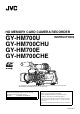
HD MEMORY CARD CAMERA RECORDER GY-HM700U GY-HM700CHU GY-HM700E GY-HM700CHE INSTRUCTIONS * The illustration shows the GY-HM700E with the supplied viewfinder, microphone and lens attached. * GY-HM700CHU/GY-HM700CHE does not come with a lens. For Customer Use: Enter below the Serial No. which is located on the body. Retain this information for future reference. Model No. GY-HM700U/GY-HM700CHU Serial No. Please read the following before getting started: Thank you for purchasing this JVC product.
Introduction FOR USA These are general IMPORTANT SAFEGUARDS and certain items may not apply to all appliances. IMPORTANT SAFEGUARDS 1. 2. 3. 4. Read all of these instructions. Save these instructions for later use. All warnings on the product and in the operating instructions should be adhered to. Unplug this appliance system from the wall outlet before cleaning. Do not use liquid cleaners or aerosol cleaners. Use a damp cloth for cleaning. 5.
Safety Precautions POUR CANADA ATTENTION RISQUE D’ELECTROCUTION NE PAS OUVRIR FOR USA AND CANADA CAUTION RISK OF ELECTRIC SHOCK DO NOT OPEN ATT ENTION: POUR EVITER TOUT RISQUE D’ELECTROCUTION NE PAS OUVRIR LE BOITER. AUCUNE PIECE INTERIEURE N’EST A REGLER PAR L’UTILISATEUR. SE REFERER A UN AGENT QUALIFIE EN CAS DE PROBLEME. Le symbole de l’éclair à l’intérieur d’un triangle équilatéral est destiné à alerter l’utilisateur sur la présence d’une “tension dangereuse” non isolée dans le boîtier du produit.
Introduction Safety Precautions (continued) Information for Users on Disposal of Old Equipment [European Union] FOR EUROPE This equipment is in conformity with the provisions and protection requirements of the corresponding European Directives. This equipment is designed for professional video appliances and can be used in the following environments: ● Controlled EMC environment (for example, purpose-built broad-casting or recording studio), and rural outdoors environments.
V
Introduction Contents Introduction Precautions for Proper Use . . . . . . . . . . . . . . . . . . . . . . . . . 5 Operation Mode . . . . . . . . . . . . . . . . . . . . . . . . . . . . . . . . . . 7 Names of Parts . . . . . . . . . . . . . . . . . . . . . . . . . . . . . . . . . . 8 Side Control Panel . . . . . . . . . . . . . . . . . . . . . . . . . . . . 10 Viewfinder . . . . . . . . . . . . . . . . . . . . . . . . . . . . . . . . . . 11 LCD Monitor . . . . . . . . . . . . . . . . . . . . . . . . . . .
Menu Display and Detailed Settings Connecting External Devices Basic Operations in Menu Screen . . . . . . . . . . . . . . . . . . . 66 Display and Description of the Menu Screen . . . . . . . . 66 Text Input with Software Keyboard . . . . . . . . . . . . . . . . 67 Menu Screen Hierarchical Chart . . . . . . . . . . . . . . . . . . . . 68 Main Menu Screen . . . . . . . . . . . . . . . . . . . . . . . . . . . . . . 70 Record Set Menu . . . . . . . . . . . . . . . . . . . . . . . . . . . . . . . .
Introduction Main Features New Viewfinder With a high resolution of 852x480 in 0.425 inches, the new viewfinder is now more robust and enables more accurate focusing. This camera recorder enables recording of HD format images on an SDHC card, and also playback of these images. High Resolution LCD Monitor Equipped with a 4.3 inch 800x480 large LCD monitor, both shooting precision and viewing performance are improved.
Precautions for Proper Use Power Saving 䡵 When this device is not in use, be sure to set the [POWER] switch to AOFFB in order to reduce power consumption. Batteries Storage and Usage Locations 䡵 Allowable ambient temperature and humidity Be sure to use this device within the allowable temperature range of 0 I to 40 I and a relative humidity of 30 % to 80 %.
Introduction Precautions for Proper Use (continued) Handling of SDHC Cards 䡵 The access lamp lights up in red when data on the SDHC card is being accessed. Do not remove the SDHC card during data access (such as recording, playback, or formatting). Do not turn off the power or remove the battery and AC adapter during access either. LCD Monitor and Viewfinder 䡵 The LCD monitor and viewfinder screens are manufactured using high-precision technology.
Operation Mode This camera recorder has three operation modes - Camera mode, Media mode, and USB mode. The operation mode indicator on the left side of the camera recorder lights up according to the mode.
Introduction Names of Parts N ML K J Viewfinder (A Page 11) A B F G H I LCD Monitor (A Page 11) Zoom Lens (A Page 14) CDE Side Control Panel (A Page 10) A Front Tally Lamp (A Page 30) (A Page 87) J Monitor Speaker (Cheek Pad) (A Page 26) B Viewfinder Cable Clamp (A Page 20) K Shoe C [ZEBRA ON/OFF] Zebra ON/OFF Switch (A Page 18) For mounting separately sold lights and accessories.
a Z Y X W W V O P Battery Mount (A Page 21) SDHC Slot (A Page 13) QR S T U Side Terminal (A Page 12) O Back Tally Lamp (A Page 30) (A Page 87) P [PHONES] Earphone Connector (3.5) (A Page 45) Q [LENS] Lens Connector (12-pin Connector) X [FOCUS ASSIST] Focus Assist Button (A Page 35) Y Record Button Lock Switch (A Page 19) Set the switch toward the lens to lock the [REC] trigger button Z.
Introduction Names of Parts (continued) Memo : ● Set the functions of the [USER1,USER2,USER3] buttons in the menu. (A Page 74) ● When the menu screen is displayed, these buttons function as the menu operation buttons.
Memo : ● When [Camera Function][Switch Set...]B[AE LEVEL] is set to AAE LEVEL/VFRB, the cross-shaped button is used to set the number of frames during Variable Frame REC. ( A Page 56 [Variable Frame REC]) ( A Page 75 [AE LEVEL]) 䡵 During Media mode (SD Card mode) (A Page 57) Thumbnail operation : Cross-shaped button (JKHI), center Set button (R) LCD Monitor A O Operation Mode Indicator Lights up as below according to the operation mode.
Introduction Names of Parts (continued) J Shoulder Pad Slide Button For adjusting the shoulder pad position. Press this button to adjust the shoulder pad K position to the front or back. K Shoulder Pad L [USB] USB Terminal (A Page 115) M [IEEE1394] IEEE1394 Terminal (4-pin) Side Terminal A M B C D E F L Note : ● When connecting IEEE1394 cables, check that the connectors are facing the right direction before you insert. Memo : ● Put on the covers when the connectors are not in use.
SD Slot Rear (A Page 31) E D A A C A B B C A Card Slot A Status Indicator A Shoulder Belt Mount (x2) B [SLOT SELECT] Card Slot Selection Button For mounting a shoulder belt (sold separately). For switching SDHC cards. Note : C SDHC Card Cover D Card Slot B Status Indicator E [OPEN] SDHC Card Cover Open/Close Knob ● Be sure to use a shoulder belt with the strength to withstand the weight of this camera recorder.
Introduction Names of Parts (continued) Zoom Lens C B To operate zoom servo with the zoom servo control lever, set the [ZOOM] switch M to ASERVOB. ● Zooms into wide angle and increases the angle of view when AWB is pressed. ● Zooms into telephoto and decreases the angle of view when ATB is pressed. ● Zoom speed increases when the lever is pressed hard. H Iris Mode Switch (Supplied with GY-HM700U/GY-HM700E only) CANON KT14 x 4.4KRSJ G Zoom Servo Control Lever A : Auto iris operation mode.
Basic System Diagram Shoulder Belt SDI Cable BNC Component Cable BNC Microphone MV-P615 Monitor XLR 3P Composite Cable BNC Earphone Audio Cable RCA pin Focus Manual Unit HZ-FM13 (FUJINON) HZ-FM15 (CANON) Monitor Microphone External Recording Device IEEE1394 Cable 4P-6P 1/3 Zoom Lens Th13x3.5BRMU(FUJINON) For GY-HM700CHU/GY-HM700U VTR M PL Mount Film Lens 16 mm PL Mount Film Lens adapter HZ-CA13U 1/3 Zoom Lens KT14x4.
Introduction Displays on the LCD Monitor and Viewfinder LCD monitor display The display switches between the 5 screen types with every press of the [STATUS] button. (STATUS 0B1B2B3B4B0) Press the [DISPLAY] button to switch to the enlarged status display screen. (A Page 17) 30/24 fps You can display the camera status, media information, zebra pattern, and various markers in the video image on the LCD monitor and viewfinder screens during shooting.
䡵Status Screen (VF/LCD) During Clip Playback in Media Mode (SD Card Mode) (A Page 96) 䡵Status Screen in USB Mode This screen displays the USB mode. The display switches between the 3 screen types with every press of the [STATUS] button. (STATUS 0B1B2B0) Enlarged Status Display on LCD Monitor STATUS 0 Screen You can enlarge and display only the characters of the status screen on the LCD monitor.
Introduction Displays on the LCD Monitor and Viewfinder (continued) Auto White Display (Camera Mode Only) Alarm Display ● Alarm is displayed during the status screen display in Camera mode (STATUS 0, 1, 4) and Media mode. If the alarm sounds during STATUS 2 or 3 Screen display in Camera mode, the display will return to STATUS 0 Screen and alarm will be displayed. ( A Page 119 [Error Displays and Actions]) Displays the operation and result when Auto White Balance is activated.
Preparations Attaching Accessories Attaching the Microphone (Supplied) You can attach the supplied microphone to the microphone holder. The supplied microphone has a phantom power supply. 1 Turn the knob on the microphone holder anticlockwise to loosen and open the microphone holder. Attaching the Zoom Lens (Supplied with GY-HM700U/GY-HM700E only) 2 Place the microphone in the microphone holder. 3 Turn the knob on the microphone holder clockwise to secure the microphone.
Preparations Attaching Accessories (continued) Power Supply Attaching the Viewfinder (Supplied) 1 Slide the viewfinder in the direction of the arrow to attach it. 2 Turn the slide lock ring to secure the position of the viewfinder. Slide Lock Ring 2 1 Viewfinder 3 Attach the viewfinder cable to the viewfinder terminal. 4 Pin the viewfinder cable to the clamp. 4 3 20 Clamp To use this camera recorder, you can attach a battery pack or connect an AC adapter to it.
Using AC Power (DC IN Power) Use an AC adapter (sold separately) to operate the camera recorder with AC power. 1 Connect the DC cable of the AC adapter to the [DC INPUT] terminal of the camera recorder. Check that the power of the camera recorder and the AC adapter is turned AOFFB and connect as shown in the diagram.
Preparations Using a Battery Pack (continued) Attaching the Battery (GY-HM700CHU/GYHM700U) Use the Dionic90 (Anton Bauer) battery. 1 Align the battery guide pins (x3) with the battery, Attaching the Battery (GY-HM700CHE/GYHM700E) Use the Endura-7 (IDX) battery. 1 Attach the battery. Face the terminal downward and attach the V mount of the battery onto the V mount attachment bracket of the camera recorder. V Mount Attachment V Mount adapter, and guide hole and insert straight.
Note : Power Status Display 䡵Viewfinder and LCD Monitor Screens The power status is displayed on the status and menu screens. If the battery or supplied voltage from the AC adapter is low, a warning will be displayed in red. ● The remaining battery power and time are displayed as there are from the battery information. Accurate data may not be displayed according to the battery condition. Replace the battery as soon as possible when the remaining battery power and time are low.
Preparations Turning On/Off the Power 䡵 Camera mode Camera images are output on the viewfinder and LCD monitor. When a recordable SDHC card is inserted, the camera recorder enters the recording standby mode. ASTBYB appears on the operation mode display area of the LCD monitor and viewfinder. Press the [REC] trigger button to start recording. Memo : Turning On the Power ● Playback of SDHC card is not possible in Camera mode.
( Setting the Clock (Initial Setting) 2 Specify [Time Zone] and [Date/Time]. A Move the cursor with the cross-shaped button (HI) and select the setting item. B Change the values with the cross-shaped button (JK). Set the date/time of the built-in clock in the [Initial Setting] screen. The configured date/time data is saved in the built-in rechargeable battery even if the power is turned off. 3 Press the Set button after setting is complete. The clock is set to 0 seconds of the input date/time.
Preparations Setting the Clock (Initial Setting) (continued) Changing the Display Style Adjusting the Monitor Speaker The monitor speaker can be rotated 180 degrees. Adjust according to the position of your ear. You can change the display style of the date/time on the menu. 180 Degrees Rotation Memo : ● To perform the settings while looking at the monitor screen connected to the video signal output terminal, set [Analog Out Char.] or [SDI Out Char.] in the [A/V Out] menu to AOnB.
Adjusting Back Focus 1 Set the iris mode switch of the lens to AMB (manual). 2 Set the zoom mode switch to AMANU.B (manual). 3 Turn to open the iris ring. When the lens is first attached, adjust the back focus of the lens if the focus is not clear when zoomed to the telephoto or wide angle end. ● Place an object 3 m and above away from the camera. ● The Siemens Star Chart is most suitable as the object. 3 4, 6 Adjust the lighting such that the optimum image level can be obtained.
Preparations Adjusting the LCD Monitor and Viewfinder Adjusting the LCD Monitor You can change the angle and brightness of the LCD monitor screen according to your usage condition. Changing the brightness of the screen will not affect the recorded images. [LCD BRIGHT +/-] Button ● Use the [LCD PEAKING +/-] button to adjust the contour of the LCD monitor screen. Press the [+] and [-] buttons simultaneously to return to standard settings. [+] : Press the button to increase contour correction.
䡵Adjusting the Angle Adjust the position and angle of the viewfinder. 䡵Adjusting the Visibility Turn the eyepiece focus ring to sharpen the image on the viewfinder screen. 䡵Adjusting the Viewfinder Screen Adjusting contour and brightness ● Use the [VF BRIGHT] knob to adjust the brightness of the viewfinder screen. ● Use the [VF PEAKING] knob to adjust the contour of the viewfinder screen.
Preparations Tally Lamps These are indicator lamps for recording and warning. The operation changes according to the menu settings. When the battery or remaining space on the SDHC card is low, the lamps blink. (Camera mode only) * Set using [Tally System]/[Front Tally]/[Back Tally] in the [Main Menu]B[Others...] menu.
䡵Card Slot Status Indicator SDHC Cards The following table shows the respective states of slot A and B. Lamp Slot Status Lights up in red Inserted SDHC card is being accessed. (writing/reading data) Do not turn off the power of the camera recorder or remove the SDHC card. Lights up in green On standby. Inserted SDHC card can be used for recording or playback. Light goes out ● SDHC card is not inserted.
Preparations SDHC Cards (continued) 2 Select the slot of the SDHC card to be formatted and press the Set button. 2 Switching SDHC cards When both card slots are inserted with SDHC cards, you can use the [SLOT SELECT] button to switch the card to use. When the memory on an SDHC card is full during recording, data recording automatically switches to the other card. [SLOT SELECT] Button 3 The status of the selected SDHC card appears. 4 Select [Format] and press the Set button.
Note : Restoring the SDHC Card It is necessary to restore the SDHC card if an abnormality occurs to the data in the card due to some reasons. The message ARestore MediaB appears on the LCD monitor/ viewfinder screen when an SDHC card that requires restoring is inserted. Memo : ● To cancel the message display, press the [CANCEL] button. A [!] mark appears at the remaining media display area when an SDHC card that requires formatting is inserted. 1 Select [Restore Media] in the [Media...] menu.
Shooting Basic Shooting Procedures [REC] Button Back Tally Lamp 1 3 Front Tally Lamp 2 5 4 [POWER] Switch [REC] Button 2 Press the [REC] button to start recording to the SDHC Preparations card. 1 Attach the accessories. (A Page 19) 2 Supply battery or AC adapter power to the camera recorder. (A Page 21) 3 Insert an SDHC card. (A Page 31) 4 Turn on the power of the camera recorder. Set the [POWER] switch to AONB. The camera recorder starts up in Camera mode and is ready for shooting.
Focus Assist Function Recording Clips When the [FOCUS ASSIST] button is pressed during shooting, the focused area is displayed in color (blue, red, or green). This enables easy and accurate focusing. Select the color in the menu. 䡵Clip (Recorded Data) and Clip Name [FOCUS ASSIST] Button When recording is stopped, the images, audio and accompanying data which are recorded from start to stop are recorded as one “clip” on the SDHC card.
Shooting Selecting File and Video Formats Record Format File Format Camera Resolution Horizontal×Line MP4 1280x720 Remarks Frame & Bit Rate 60p(HQ) 60p(SP) You can select the file format for recording/playback and the record format for video images on this camera recorder. HDV compatible 30p(HQ) 30p(SP) HDV compatible 24p(HQ) Selecting a File Format 24p(SP) There are two file formats for selection.
Adjusting the Iris You can adjust the aperture of the lens iris manually or automatically according to the brightness of the object. Iris Ring Setting Gain This function electrically boosts the light sensitivity when there is insufficient illumination on the object. You can set the gain of the video amplifier according to the brightness of the object. Select the setting mode according to your shooting conditions.
Shooting Setting the Electronic Shutter 䡵Switching Shutter Speed When shutter is ON, use the [SHUTTER] switch (JK) to set the shutter speed. Shutter speed differs according to the video format and variable frame rate settings. 䡵 During modes other than Variable Frame REC You can change the shutter speed (time for each shooting frame) using the electronic shutter function. Electronic shutter can be adjusted manually or automatically.
Shutter Camera Resolution/ Frame & Bit Rate Frame Rate 720/25p 50, 25, 12.5 J Button Step (Standard) K Button 1/10000 1/4000 1/4000 1/2000 1/2000 1/1000 1/1000 1/500 1/500 1/250 1/250 1/120 1/120 1/50 1/50 1/40 1/25 1/20 1/12.5 1/10 1/6.25 J Button 1/5 1/10489.5 (Upper limit) to Variable K Button 40, 20, 10 1/10000 (Lower limit) 1/50.00 1/40.00 Memo : ● Shutter speed is usually displayed in seconds (SEC).
Shooting Adjusting the White Balance Adjust the white balance according to the color temperature of the lighting. You can select the adjustment mode according to the shooting conditions. As the color of the light (color temperature) varies according to the light source, it is necessary to readjust the white balance when the main light source illuminating the object changes. [WHT.BAL.
䡵 Error message If the white balance adjustment is not correctly completed, one of the following messages will appear for about 5 seconds. Error Message Status NG : OBJECT The object used is defective. Displayed when there is not enough white color on the object, or when the color temperature is not suitable. Use another white object and adjust the white balance again. ERROR : LOW LIGHT Insufficient illumination. Displayed when the lighting is dark.
Shooting Adjusting the White Shading You need to adjust white shading when you change the lens. Even if white balance is adjusted in the center of the screen, the top and bottom of the screen may not be adjusted. In this case, green and yellow colors may appear on the screen. This is due to the characteristic of the lens. Correcting this phenomena is known as white shading adjustment. Perform this adjustment after adjusting the white balance.
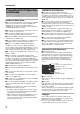
Setting the ND Filter Use the ND filter to keep the lens aperture in the appropriate range. Switch according to the brightness of the object. When the switch is changed, the position of the switched ND filter is displayed on the LCD monitor and viewfinder screens. (STATUS 1 Screen) [ND FILTER] Switch 1280x720 30/24 fps 24p HQ A 100min B 100min STBY 00:00:00:00 MAX 123% MIN 45% SKIN AREA S.
Shooting Adjusting Audio Input Settings and Recording Level Adjusting Audio Recording Level You can select to adjust the audio recording levels for the two channels (CH-1/CH-2) manually or automatically. You can record audio from the two channels (CH-1/CH-2) in synchronization with video images on this camera recorder. The camera recorder is equipped with [INPUT1] and [INPUT2] terminals for audio input. You can select a recording channel and the adjustment mode (manual/ automatic).
Note : 䡵Using Stereo Type Earphone Jack ● When the [FULL AUTO] switch on the camera recorder is set to AONB, the recording level cannot be adjusted with the [AUDIO LEVEL CH-1/CH-2] adjustment knob. When a stereo type earphone jack is connected, perform the following setting to output stereo sound. 1 Set the [MONITOR SELECT] switch to ABOTHB.
Shooting Setting Time Code and User’s Bit Time code and user’s bit data are recorded with the video in this camera recorder. The time code and user’s bit are displayed on the viewfinder and LCD screens during playback or recording. (Status screen) Memo : ● The built-in time code generator number is displayed. ● Time code display for [IEEE1394] input is not supported. ● Values recorded on the SDHC card is displayed in Media mode.
䡵Setting Time Code Presetting the Time Code Time code and user’s bit data generated from the internal time code generator are recorded. This section describes how to set [TC Preset] in the [TC/UB] menu. (A Page 82) [USER2] Button [MENU] Button Set Button (R) [USER2] Button CrossShaped Button (JKHI) [CANCEL] Button [TC GENE.] Setting Switch 1 Select [Main Menu]B[TC/UB]B[TC Preset] and press the Set button (R). (A Page 82) The [TC Preset] screen appears.
Shooting Setting Time Code and User’s Bit (continued) 3 Check the values and press the cross-shaped button (R). ● The time code is set and the screen returns to [TC/UB]. ● To cancel the setting, press the [CANCEL] button. 4 Press the [MENU] button. Returns to the normal screen. Presetting the User’s Bit You can add an 8-digit hexadecimal number as the user’s bit to the recorded image.
2 Set the time code (hour, minute, second, frame). 2 Set the user’s bit. Use the cross-shaped button (H, I) to place the cursor at the item to set, then the cross-shaped button (J, K) to change the values. Use the cross-shaped button (H, I) to place the cursor at the item to set, then the cross-shaped button (J, K) to change the values. Memo : Memo : 3 Check the values and press the cross-shaped button (R). 3 Check the values and press the cross-shaped button (R).
Shooting Setting Zebra Pattern Memo : ● ATop2B and ABottom2B cannot be set if [Zebra] is set to A1PatternB. ● When the specified range of two zebra patterns overlaps, the two zebra patterns overlap and are displayed in a grid. When the luminance level range for displaying zebra patterns is specified, diagonal lines (zebra pattern) are displayed at areas with the specified luminance levels during shooting.
3 Flip the [SKIN AREA/SPOT METER] switch of the camera Setting Spot Meter recorder. The operation switches as below when the [SKIN AREA/ SPOT METER] switch is flipped. The brightness of the object during shooting is displayed. This function is useful when setting video or stage lighting or when specifying camera exposure. A cursor indicating the location and the brightness (%) of that location are displayed in the images shown on the LCD monitor and viewfinder screens.
Shooting [ Setting Spot Meter (continued) Viewing Recorded Videos Immediately (Clip Review) 䡵 When [Manual] is selected A [SPOT METER FIXED] is displayed when the switch is flipped. The brightness of the cursor position is displayed. You can check (review) the last recorded video clip on the screen. However, the video clip cannot be played back if the settings of the camera recorder are different from the video format (Camera Resolution/Frame & Bit Rate) of the clip.
Note : ● During Clip Review, only the [CANCEL] and [REC] buttons are enabled. Press the [CANCEL] button to cancel clip review and return to ASTBYB (recording standby) mode. Press the [REC] button to cancel clip review and enter recording mode. It will take some time to start recording after the button is pressed. ● When the last clip is less than 5 seconds, the whole clip is played back. ● Only video clips in the currently selected slot can be reviewed.
Shooting Protecting Important Scenes (OK Mark Function) You can append OK marks to the clips for important scenes. Clips appended with OK marks cannot be deleted, thus protecting the important clips. In addition, you can display only the clips with OK marks in the thumbnail display during Media mode. Special Recording Besides the normal recording mode, three special recording methods are available in this camera recorder. They are Pre REC, Clip Continuous REC, and Variable Frame REC.
6 Resume recording. (Recording 3) Clip Continuous REC In normal recording, when the recording stops, the image, audio, and accompanying data from the start till the end of the recording are recorded as one AclipB on the SDHC card. This mode allows you to consolidate several rounds of Astartstop recordingB into one clip. Example: In normal recording, three clips are generated as Recording 1, Recording 2, and Recording 3. However, recording in this mode generates only one clip.
Shooting Note : Special Recording (continued) Variable Frame REC Shooting in this mode allows you to obtain smooth slow motion or quick motion videos. Using different frame rate settings for recording and playback., videos captured at normal speed can be played back more smoothly than those in low or high speed playback. Variable Frame REC is only enabled under the following situations. ● [Camera Resolution] in the [Record Format] menu is set to A1280x720B.
Playback Playing Back Recorded Clips Thumbnail Screen To play back clips recorded on SDHC cards, switch to the Media mode (SD Card mode). Press the [CAM/MEDIA] selection button in Camera mode to enter SD Card mode. A thumbnail screen of the clips recorded on the SDHC card is displayed. You can play back the selected clip on the thumbnail screen. Memo : ● When an SDHC card without any clips is inserted, ANo ClipsB is displayed.
Playback Playing Back Recorded Clips (continued) Name D Video Format Thumbnail Screen (continued) 䡵No Detailed Properties (4x3 Thumbnails) Screen (continued) Displays the video format (Camera Resolution/Frame Rate) that allows playback and thumbnail display. Available in 4 types: [1080/60i, 30p, 24p], [1080/50i, 25p], [720/60p, 30p, 24p], and [720/50p, 25p]. Clips of other video formats are represented in alternative display.
Name I Clip Mark Description Displays clip information (properties). A B C A OK Mark Clip is appended with OK mark. Memo : ● Clips appended with OK marks cannot be deleted on the camera recorder. B Continued From Mark This mark indicates that the current clip is continued from another SDHC card when recording is divided and made on several SDHC cards.
Playback Playing Back Recorded Clips (continued) Name C Detailed Properties Thumbnail Screen (continued) 䡵Detailed Properties (4x1 Thumbnails) Screen A D Operation B Guide Description Shows the detailed properties of the selected clip. The following information is displayed.
Thumbnail Menu Playing Back Use the operation buttons on the side control panel of the camera recorder to play back. A B Press the [MENU] button during thumbnail display to display the thumbnail menu. Press the [MENU] button during menu display to cancel the settings and exit the menu. Thumbnail Menu Sub-Menu C Name A B C Button Description Plays back/pauses the selected clip. Button Skips in the reverse or forward direction. Button Fast forwards in the reverse or forward direction.
Playback 2 Press the [USER2] button. Deleting Clips A screen to confirm deletion appears. 3 Use the cross-shaped button (JK) to select [Delete] and press the Set button (R) Deleting starts. For deleting clips. [USER2] Button [MENU] Button Set Button (R) 3 CrossShaped Button (JKHI) [CANCEL] Button Note : ● Clips appended with OK marks cannot be deleted on the camera recorder. ● Read-only clips can be deleted on a PC.
4 Use the cross-shaped button (JK) to select [Delete] and press the Set button (R) Deleting starts. 3 Memo : ● Button operations are unavailable during deletion. The deleting operation cannot be canceled. ● The cursor moves to the next clip (or previous clip if a next clip does not exist) after deletion. Deleting All Clips Deletes all clips that are displayed. 1 Press the [MENU] button. The thumbnail menu screen appears. 2 Select [Delete Clip...]B[All Clips] in the menu.
Playback Appending and Deleting OK Marks OK Mark You can append OK marks to the clips for important scenes. Clips appended with OK marks cannot be deleted, thus protecting the important clips. When the camera recorder is in Media mode (SD Card mode), you can delete the [OK] marks appended during recording, or append/delete [OK] marks after shooting.
䡵During Playback or Pause Screen Deleting OK Marks 䡵During Thumbnail Screen 1 Select a clip to delete OK mark and press the [USER1] button. The OK mark is deleted. 1 Press the [USER1] button when playing back a clip appended with OK mark. The OK mark is deleted. 1 Memo : ● The [USER1] button is disabled (displayed in gray) and OK marks cannot be deleted when the write-protect switch of the SDHC card is set ( is displayed). ● AOK Mark Added...B/AOK Mark Deleted...
Menu Display and Detailed Settings Basic Operations in Menu Screen Display and Description of the Menu Screen 䡵Screens of the Selected Menu Items Press the [MENU] button on the side control panel of the camera recorder to display the menu screen on the LCD monitor and viewfinder. Various settings for shooting and playback can be configured on the menu screen. The menu screen can also be displayed on external monitors connected to the video signal output terminal. ( A Page 86 [Analog Out Char.
䡵Changing Setting Values A 䡵[Clip Name Prefix] C A D B E F F D B E Name A Menu Item to Change Name Description Menu item to be changed. A list of setting values C appears in a pop-up. B Operation Guide Guide for the current operation buttons. C List of Setting A pop-up displaying a list of setting values for selection. The height of the pop-up depends on the number of settings available. Use the scroll bar D to confirm the current display status.
Menu Display and Detailed Settings Menu Screen Hierarchical Chart Main Menu... (A Page 70) Record Set...(A Page 71) Record Format(A Page 71) File Format Camera Resolution Frame & Bit Rate Rec Mode (A Page 71) Clip Set (A Page 72) Clip Name Prefix Reset Clip Number Audio Set (A Page 72) Input1 Mic Ref. Input2 Mic Ref. Mic Wind Cut Audio Ref. Level Audio Limiter Test Tone Camera Function...
TC/UB... (A Page 82) TC Preset UB Preset Drop LCD/VF... (A Page 82) Shooting Assist... (A Page 83) Marker Setting... (A Page 84) Status Display... (A Page 84) LCD + VF VF Display LCD Mirror Mode A/V Out... (A Page 86) Output Terminal Down Convert Set Up HD/SD-SDI Out Analog Out Char. SDI Out Char. Audio Monitor Others... (A Page 87) Alarm Level Mode LED Tally System Front Tally Back Tally 1394 Rec Trigger 1394 Auto Power Off Reset All Date/Time Time Zone System Information Media...
Menu Display and Detailed Settings Main Menu Screen Some menus cannot be set depending on the operating mode or status of the camera. These items are displayed in gray, and they cannot be selected. Item Record Set Function Menu screen for specifying video or audio settings during shooting and playback. The cursor does not move to this item during recording or in Media mode. (A Page 71) Camera Function Menu screen for specifying operation settings during shooting.
Record Set Menu Record Format Menu * Default values are indicated in bold characters. Item File Format Setting Values QuickTime MP4 Function For selecting the format of the file to be recorded to the SDHC card. Note : ● AMP4B can only be selected when KA-MR100G (Memory Recorder) is connected. Camera Resolution 1920x1080 1440x1080, 1280x720 For selecting the size of the recorded images. (Horizontal x vertical) The selectable values of [Frame & Bit Rate] vary according to the setting of this item.
Menu Display and Detailed Settings Record Set Menu (continued) Clip Set Menu * Default values are indicated in bold characters. Item Clip Name Prefix Setting Values xxxG (The default value of xxx is the last 3 digits of the serial number.) ^ Reset Clip Number Function For setting the first 4 characters of the name of the clip file to be recorded to the SDHC card.
Camera Function Menu * Default values are indicated in bold characters. Item Bars Setting Values On Off Function For setting whether to output color bars. On : Color bars are output. Off : Color bars are not output. Memo : ● When the [FULL AUTO] switch on the camera recorder is set to AONB, and [Bars] in the [FULL AUTO...] menu is set to AOffB, this item is set to AOffB automatically. (A Page 75) Shutter EEI Variable Step AE LEVEL AE Speed +3 to +1, For specifying shutter-related settings.
Menu Display and Detailed Settings Camera Function Menu (continued) Switch Set... Item * Default values are indicated in bold characters. Item FAW Setting Values None PRESET A B GAIN L GAIN M GAIN H USER1 USER2 USER3 ALC, 18dB, 15dB, 12dB, 9dB, 6dB, 3dB, 0dB Function For assigning the FAW (Fulltime Auto White Balance) function to a position on the [WHT.BAL.] selection switch. This is fixed at AFAWB when the [FULL AUTO] switch of the camera recorder is set to AONB. None : FAW function is not assigned.
* Default values are indicated in bold characters. Item SKIN A./SPOT M. Setting Values Skin Area Spot Meter Function For assigning the function of the [SKIN AREA/SPOT METER] switch on the camera recorder. Skin Area : Assigns the Skin Detail function and its area display. Spot Meter : Assigns the Spot Meter display function. Memo : ● When ASkin AreaB is selected, [Skin Detect] is forcibly set to AOnB when the [SKIN AREA/ SPOT METER] switch is flipped, even if [Skin Detect] is set to AOffB.
Menu Display and Detailed Settings Camera Process Menu * Default values are indicated in bold characters. Item Detail Setting Values Max, 9 to 1, Normal, -1 to -9, Min, Off Adjust... Function For adjusting the contour (detail) enhancement level. Increase the number : Sharpens the contour. Decrease the number : Softens the contour. Off : Disables this function. For specifying the detailed settings of the contour (detail).
* Default values are indicated in bold characters. Item White Clip Gamma Master Level Setting Values Function 100% 108% For setting the point to apply white clip for input video signals with a high luminance level. 100% : Applies white clip at the point where the luminance level is 100 %. Even when this item is set to A108%B, it switches automatically to A100%B if the screen appears too white. Set to this value when the system in use limits Y output signals within 100 %.
Menu Display and Detailed Settings Camera Process Menu (continued) Detail/Adjust... Item * Default values are indicated in bold characters. Item V/H Balance Setting Values H-Max, 4 to1, Normal, -1 to -4, H-Min H Frequency High Middle Low V Frequency High Low Function For setting the H/V balance to enhance contour (detail) in the horizontal (H) or vertical (V) direction. Increase the number : Enhances contour in the horizontal direction.
White Balance... Item * Default values are indicated in bold characters. Item Preset Temp. Setting Values 5600K 3200K White Paint R Max, 30 to 1, Normal, -1 to -31, Min Function For setting the color temperature when the [WHT.BAL.] selection switch of the camera recorder is set to APRESETB. For adjusting the R (red) component in the AWB (Auto White Balance) mode. Increase the number : Strengthens the red. Decrease the number : Weakens the red. Memo : ● This item is selectable when the [WHT.BAL.
Menu Display and Detailed Settings Camera Process Menu (continued) Shading Mode/Adjust... Item * Default values are indicated in bold characters. ● This item is selectable only when [Shading Mode] is set to AManualB. [R Level], [G Level], and [B Level] cannot be selected when this is set to APresetB.
* Default values are indicated in bold characters. Item G&Cy G Level G&Cy Cy Level Setting Values Max, 19 to 1, Normal, -1 to -19, Min Function For adjusting the green/cyan level of the video toward green. Increase the number : Enhances the green component of green/cyan. Decrease the number : Reduces the green component of green/cyan. For adjusting the green/cyan level of the video toward cyan. Increase the number : Enhances the cyan component of green/cyan.
Menu Display and Detailed Settings TC/UB Menu * Default values are indicated in bold characters. Item TC Preset Setting Values UB Preset Drop Frame Function ^ For setting the time code (hour, minute, second, frame). Display : Drop setting 02:02:25.20 : Non Drop setting 02:02:25:20 ^ For setting the user’s bit. (Digit by digit) Display : AB CD EF 01 Non Drop Drop For setting the framing mode of the time code generator. Non Drop : Internal time code generator works in the non-drop-frame mode.
Shooting Assist... Item * Default values are indicated in bold characters. Item Focus Assist Setting Values ACCU-Focus Normal Color Blue Green Red Level High Middle Low Zebra 2Patterns 1Pattern Top1 Bottom1 Top2 Over, 100% to 85%, 80%, 75% to 5% (In 5 % increments) 100% to 75%, 70%, 65% to 0% (In 5 % increments) Over, 100% to 5% (In 5 % increments) Function For specifying the operation when the [FOCUS ASSIST] button on the camera recorder is pressed.
Menu Display and Detailed Settings LCD/VF Menu (continued) Marker Setting... Item ( A Page 100 [Marker and Safety Zone Displays (Camera Mode Only)]) * Default values are indicated in bold characters. Item Aspect Ratio *1 Setting Values 4:3, 14:9, 16:9, Function For selecting the final image aspect ratio to be used from the overall angle of view. 16:9(+4:3), 2.35:1 Center, 2.35:1C.HeadRM, 1.85:1 Center, 1.85:1C.HeadRM, 1.66:1, 1.
* Default values are indicated in bold characters. Item TC/UB Setting Values On Off Audio Meter On Off Battery Info Time Capacity% Voltage Function For specifying whether to display the time code/user’s bit rate in the status display on the LCD monitor and viewfinder screens. On : Displays the time code or user’s bit rate. Whether time code or user’s bit rate is displayed is determined by the setting of the [TC DISPLAY] switch on the inner panel of the camera recorder’s LCD monitor.
Menu Display and Detailed Settings A/V Out Menu * Default values are indicated in bold characters. Item Output Terminal Setting Values Composite Component Off Function For setting output signals from the [Y/VIDEO]/[PB]/[PR] video signal output terminal (BNC) on the side of the camera recorder. Composite : Outputs composite signals to the [Y/VIDEO] video signal output terminal. Component : Outputs component signals. Off : Signals are not output.
* Default values are indicated in bold characters. Item Audio Monitor Setting Values Stereo Mix Function For setting the audio sound of the [PHONES] terminal to stereo or mixed sound when the [MONITOR SELECT] switch on the side of the camera recorder is set to ABothB. Mix : Outputs mixed sound (outputs mixed sound of CH-1 and CH-2 to both L and R). Stereo : Outputs stereo sound (outputs audio sound of CH-1 to L, and CH-2 to R). When a monitor speaker is used, only the audio sound of CH-1 is output.
Menu Display and Detailed Settings Others Menu (continued) * Default values are indicated in bold characters. Item 1394 Rec Trigger Setting Values Ext Series Split Synchronize Off Function For setting the recording trigger for the external recording device connected to the [IEEE1394] terminal. Ext : Outputs recording trigger to the external system only. (Recording is not performed by the internal system.
Media Menu * Default values are indicated in bold characters. Item Format Media Restore Media Function For formatting (initializing) an SDHC card. Select a card slot (A or B), select [Format] from [Cancel]/[Format], and press the Set button to format (initialize) the card. ( A Page 32 [Formatting (Initializing) SDHC Cards]) For restoring an SDHC card. Select a card slot (A or B), select [Restore] from [Cancel]/[Restore], and press the Set button to restore the SDHC card.
Status Screen Status Screen in Camera Mode STATUS 0 Screen M L 30/24 fps DD 20 min A 1min B 1min STBY RES F5.6 B C A MAX 123% MIN 45% SKIN AREA S.DTL B -3 A<3200K> AE+1 9dB 1/10000 D E * Appears only when a warning is displayed (A Page 92) K J I H G F * Item Description A Media Status ---STBY REC REVIEW STBYP RECP STBYC B Iris Status Mark Indicates whether the brightness of the image is appropriate.
Item Description I Skin Detail Operation J Operation of Functions Appears as AS.DTLB when the Skin Detail function is turned ON. K Luminance Information Appears when the Spot Meter function is activated. For details of the display, refer to [Setting Spot Meter] (A Page 51 ). MAX : Maximum luminance MIN : Minimum luminance L Event/Warning Display Displays the settings for about 3 seconds when the gain or shutter speed is manually changed.
Status Screen Status Screen in Camera Mode (continued) STATUS 1 Screen * 0 : Same as STATUS 0 Screen (A Page 90) A B C 1280x720 30/24 fps 60p HQ OK A 100min B 100min STBY D 282min E *0 00:00:00:00 DD 20 min F5.6 MAX 123% MIN 45% SKIN AREA S.DTL B -3 ND1/16 A<3200K> AE+1 9dB 1/10000 F J I H *0 G Item Description A Resolution Displays the video image resolution. (1920⳯1080, 1440⳯1080, 1280⳯720) B Frame Rate/Bit Rate Displays the frame rate and bit rate in pairs.
Item G ND Filter Position Description Displays the current ND filter position. No display : [ND FILTER] is set to AOFFB ND1/4 : [ND FILTER] is set to A1/4B ND1/16 : [ND FILTER] is set to A1/16B Memo : ● You can turn ON/OFF the display using [Filter] of [Status Display...] in the [LCD/VF] menu. (A Page 84) H Remaining Space on External Device Displays the remaining recording time of the external device (0 to 999).
Status Screen Status Screen in Camera Mode (continued) STATUS 2 Screen CAMERA INFORMATION SETUP FILE ZEBRA1 ZEBRA2 AUDIO FORMAT MEDIA STBY *0 282min G F SCENE [ SCENE ] 50%-100% 70%-80% CH1 CH2 QuickTime A 125min B123min E D C B Jan 2. 2009 01:23:45AM *1 Item A Date/Time A * 0 : Same as STATUS 0 Screen (A Page 90) * 1 : Same as STATUS 1 Screen (A Page 92) Description Displays the current date and time. Note : ● The date/time display style can be specified at [LCD/VF]B[Status Display...
STATUS 3 Screen This screen displays a list of the functions assigned to the switches. * 1 : Appears only when a warning is displayed SWITCH ASSIGN FAW NONE GAIN [ L / M / H ] 0dB / 9dB / 12dB USER 1 BARS USER 2 B.STRETCH3 USER 3 LOAD FILE RET CLIP REVIEW SKIN/SPOT SPOT METER A 1min AE LEVEL AE LEVEL/VFR B 1min Jan 2.
Status Screen Status Screen in SD Card Mode These are the status screens displayed in Media mode (SD Card mode, Media mode). STATUS 0 Screen This screen displays the media status or event. It is also used to display warnings only. STATUS 1 and STATUS 2 Screens F A B C DE F A B C DE OK OK J I H G K J STATUS 1 Screen I H G STATUS 2 Screen Item Description A OK Mark B Resolution Appears when an OK mark is added.
Item G Date/Time Description Displays the date/time that is recorded on the currently played SDHC card. Note : ● The date/time display style can be specified at [LCD/VF]B[Status Display...]B[Date Style]/[Time Style]. (A Page 85) H Audio Level Meter -20 dB -10 dB Displays the audio level for CH-1 and CH-2. The positions of -20 dB and -10 dB are displayed as AoB. Memo : ● You can turn ON/OFF the display using [Audio Meter] of [Status Display...] in the [LCD/VF] menu.
Status Screen Status Screen in 1394 Mode These are the status screens displayed in Media mode (IEEE1394 Input mode). STATUS 1 Screen [Event/Warning Display Area] (A Page 91 ) RES * Appears only when a warning is displayed [Voltage/Remaining Battery Power] (A Page 98 ) STATUS 2 Screen B A [Event/Warning Display Area] (A Page 91 ) 1280x720 24p HQ 282min D Item A Frame Rate/Bit Rate B Resolution Display C Audio Level Meter C Description Displays the frame rate and bit rate in pairs.
Enlarged Status Display on LCD Monitor You can enlarge and display only the characters of the status screen on the LCD monitor. A CH1 CH2 B C D DF FREE STBY J A DD 1280 x 720 min 60p HQ 100min 67.8min B 123 min OK E F G I STOP REC REVIEW H Item A Audio Level Meter STBY Description Displays the audio levels of [CH-1] and [CH-2]. If the reference audio level (A-20dBB or A-12dBB) is exceeded, this is displayed in yellow. The AOverB area is displayed in red. A48kB is the sampling frequency.
Camera Features Marker and Safety Zone Displays (Camera Mode Only) The marker and safety zone displays are useful in helping you determine the angle of view for the image according to the shooting purpose.
[Safety Zone] Display 䡵 When [Aspect Ratio] = A4:3B, [Aspect Marker] = AHalftoneB, and [Center Mark] = AOnB [Off] [95%] [93%] [90%] [88%] [80%] [Center Mark] Display 䡵 When [Aspect Ratio] = A4:3B, [Aspect Marker] = AHalftoneB, and [Safety Zone] = A80%B [Off] [On] 䡵 When [Aspect Ratio] = A4:3B, [Aspect Marker] = AHalftoneB, and [Safety Zone] = AOffB [Off] [On] 101
Camera Features 䡵Color Range Setting Smoothening the Skin Color (Skin Detail Function) 1 Place the cursor at [Skin Color Range] with the crossshaped button (J, K). 2 Press the Set button or cross-shaped button (I) to move the cursor to a setting value. The Skin Detail function can be used to reduce the contour enhancement of video signals for only the skin areas so as to produce a smoother skin tone. Preparations Before Using the Skin Detail Function (Skin Adjust Function) 1 Adjust the white balance.
Checking the Preset Hue Area 1 Set the [ZEBRA ON/OFF] switch at the front of the camera recorder to the [SKIN AREA/SPOT METER] end. Doing so forcibly turns ON the Skin Adjust function temporarily, and the preset hue area is displayed in color on the LCD monitor and viewfinder. Color Bar Output Multi-format color bars can be output on this camera recorder.
Camera Features Color Matrix Adjustment R&Yl R Level R I Increase the value: Corrected Y increases Mg YI B The color matrix of the camera recorder can be adjusted to a color of the user’s preference. When shooting is performed using multiple cameras, the colors of the different cameras can be adjusted, and a color of the user’s preference can be set on this camera recorder. 13 saturation parameters and 3 hue parameters are available for adjustment.
B&Mg B Level R I Increase the value: Corrected Y increases Mg YI Decrease the value: Corrected Y decreases B G Cy 4 Adjust the hue. Adjust the hue based on the R-, G-, and B-axes. As illustrated in the chart below, increasing the value rotates the hue in the anti-clockwise direction on the vector scope, with the respective axes as the center. Decreasing the value rotates the hue in the clockwise direction.
Camera Features Reproduction of Dark Areas (Black Stretch/ Compress Function) Process the dark areas according to the balance of bright and dark areas in the image to adjust the overall balance of contrast. 1 Adjust [Black Toe] in the [Camera Process...] menu according to the captured video signals. 2 Set the luminance point (Point Level) for AStretchB or ACompressB. ● Decide the luminance point (Point Level) at which the dark areas in the image are to be stretched or compressed.
Configuring Setup Files The menu settings of can be stored on the camera recorder or an SDHC card by saving them as a setup file. Loading a saved setup file enables you to reproduce the appropriate setup state speedily. Two types of setup files are available. 䡵 Scene file: File that contains all menu settings, ranging from video format settings to image creation settings, such as device settings and shooting conditions.
Camera Features Configuring Setup Files (continued) A B Saving Setup Files C Select the [Setup File Manage] menu on the [Main Menu...] screen, and press the Set button. (A Page 89) D 2 Select [Store File...] and press the Set button. E 1 Display the [Setup File Manage] menu. 3 Select [Scene File] or [Picture File], and press the Set button. The existing files are displayed. 4 Select the file to be newly saved (or overwritten) using the cross-shaped button (J, K), and press the Set button.
6 Select [Store] from the confirmation buttons E, and 5 Select [Load] on the confirmation screen, and press press the Set button. the Set button. A confirmation screen appears. Loading starts, and ALoading...B appears on the screen. 7 Select [Store] on the confirmation screen, and press the Set button. Saving starts, and AStoring...B appears on the screen. 5 7 Memo : Memo : ● If you do not want to save the file, select [Cancel] or press the [CANCEL] button to return to the previous screen.
Connecting External Devices Connecting an External Monitor To output live or playback video images and audio sound to an external monitor, select the output signals from the camera recorder, and connect using an appropriate cable according to the monitor to be used. Connecting via Composite/Component Output Either component or composite signals can be output from the BNC terminals on the terminal area of the camera recorder.
Note : [PHONES] Terminal Audio output from the [PHONES] terminal can be selected using [Audio Monitor] in the [A/V Out] menu (A Page 87) as well as the [MONITOR SELECT] switch on the camera recorder. The different combinations of settings that are output from the [PHONES] terminal and monitor speaker are as follows.
Connecting External Devices IEEE1394 Connection (continued) 5 Set the external device to a mode that enables recording. For setting and operation of external devices, refer to the instruction manual of the respective devices. Note : Backup Recording When the camera recorder is set to Camera mode, images shot using it can be stream output from the IEEE1394 terminal.
Stream Transmission to a Non-linear Editing System Playback images on the camera recorder can be stream output during editing using a non-linear editing system. 䡵Loading to a Non-linear Editing System in Play Mode 1 Perform the following settings on the camera recorder. A Set the [HD/DV] IEEE1394 terminal mode switch to ADVB. B Set the [INT/EXT] IEEE1394 interface terminal switch to AEXTB. Memo : ● Stream transmission is only possible for DV format images. 2 Connect the IEEE1394 cable.
Connecting External Devices Managing/Editing Clips on a PC 2 Select [Change] using the cross-shaped button, and press the Set button. The camera recorder switches to USB mode. Loading Clips to the PC (USB Connection Mode) You can load clips to a PC by connecting the camera recorder to the PC via the USB port. Doing so enables clips stored in the SDHC card to be managed and edited on the PC.
Remote Control Unit Connection The switch functions of the camera recorder can be configured using the remote control unit. * Remote control units supported: RM-LP25U, RM-LP55U, and RM-P57U 1 Connect the remote control to the camera recorder. Connect the remote cable of the remote control unit to the [REMOTE] terminal on the terminal area of the camera recorder.
Connecting External Devices Remote Control Unit Connection (continued) Function 3: Available -: Not available MASTER BLACK 3 TALLY (LED) 3 CALL *4 3 PREVIEW - List of Remote Control Unit Functions AUTO KNEE 3 䡵RM-LP25U KNEE POINT 3 BARS 3 3: Available -: Not available Function SHUTTER NORMAL 3 1/100 *1, 1/120 *2 3 1/250 3 1/500 3 1/1000 3 1/2000 3 VARIABLE SPEED GAIN - -6dB 䡵RM-LP55U Function 3: Available -: Not available CAM MODE CAM, BARS 3 CONTOUR OFF, ON (LEVEL)
䡵RM-P57U Function MODE BARS, CAM 0⬚, 90⬚, 180⬚, 270⬚ GAIN WHITE BAL - SC FINE CONTOUR 3 - H.
Others Error Displays and Actions Alarm displays on the LCD monitor and viewfinder screens, as well as the tally lamps and alarm sounds are output as follows according to the alarm status. Memo : ● This camera recorder makes use of a microcomputer. Noise interference from external sources may prevent it from functioning properly. When this occurs, turn off and on the power of the camera recorder again.
Error Display Menu/Thumbnail Status Screen Screen Status Action EXT-RECORDER POWER ? ^ Power of the camera recorder is turned off while the external device connection is detected, and the same connection cannot be detected several seconds after power is turned on again. (Error displays for about 7 seconds) When making use of a connected external device, turn on the power supply on the connected device.
Others Troubleshooting Symptom Power does not turn on. Unable to start recording. Camera image is not output on the LCD monitor and viewfinder screens. Images on the LCD monitor and viewfinder screens appear dark or blurred. Playback does not start after selecting a clip thumbnail and pressing the Set button. HD/DV signals cannot be input. No sound during playback. The [CH1/CH2 AUDIO LEVEL] adjustment knob does not work. SDHC card cannot be initialized (formatted).
w Symptom The date and time are not displayed. No output from the [Y/VIDEO], [PB], and [PR] video signal output terminals. Incorrect display on the viewfinder. IEEE1394 connection between the camera recorder and the external device cannot be established (e.g., no image on the camera recorder and/or external device). Action ● The date and time are only displayed on the STATUS 2 and STATUS 3 Screens in the Camera mode (during shooting). (A Page 94)(A Page 95) ● Is [Output Terminal] in the [A/V Out...
Others Specifications Storage Section Supported media : SDHC (Class 6) Slots : x2 Video/Audio General Power : DC 12 V (10.5 V to 17 V) Power consumption : Approx. 23 W (During recording [when the camera recorder + standard lens + LCD monitor are in use]) Recording time : Video : Approx. 2.4 kg GY-HM700CHE : Approx. 2.6 kg GY-HM700U : Approx. 3.4 kg GY-HM700E : Approx. 3.
Accessories Microphone 1 Lens (GY-HM700U/GY-HM700E only) 1 Instructions 1 CD-ROM 1 Warranty Card (GY-HM700CHU/GY-HM700U only) 1 Dimensional Outline Drawing 䡵 (Unit: mm) 95 56 108.5 59.8 44.6 133 (VF MOVE) 90 40 (VF MOVE) (166) 231 225 82.3 (82.3) 242.3 291 (for ANTON BATTERY) (S.PAD MOVE) 30 209 304 (for IDX BATTERY) 210 * The specifications and appearance of this product are subject to changes for further improvement without prior notice.
GY-HM700U/GY-HM700CHU/ GY-HM700E/GY-HM700CHE HD MEMORY CARD CAMERA RECORDER 2009 Victor Company of Japan, Limited LST0904-001A