e_ka250.book Page 1 Tuesday, September 5, 2006 11:13 AM KA-HD250 STUDIO ADAPTER STUDIO ADAPTER KA-HD250 For Customer Use: Enter below the Serial No. which is located on the body. Retain this information for future reference. Model No. KA-HD250 Serial No.
e_ka250.book Page 2 Tuesday, September 5, 2006 4:10 PM INTRODUCTION These are general important Safeguards and certain items may not apply to all appliances. Important Safeguards 1. 2. 3. 4. 5. 6. 7. 8. 9. 10. 2 Read all of these instructions. Save these instructions for later use. All warnings on the product and in the operating instructions should be adhered to. Unplug this appliance system from the wall outlet before cleaning. Do not use liquid cleaners or aerosol cleaners.
e_ka250.book Page 3 Tuesday, September 5, 2006 4:10 PM Safety Precautions (For USA and Canada) CAUTION RISK OF ELECTRIC SHOCK DO NOT OPEN CAUTION: TO REDUCE THE RISK OF ELECTRIC SHOCK, DO NOT REMOVE COVER (OR BACK). NO USER SERVICEABLE PARTS INSIDE. REFER SERVICING TO QUALIFIED SERVICE PERSONNEL. THIS DEVICE COMPLIES WITH PART 15 OF THE FCC RULES.
e_ka250.book Page 4 Tuesday, September 5, 2006 4:10 PM INTRODUCTION Safety Precautions (For Europe) WARNING: TO REDUCE THE RISK OF FIRE OR ELECTRIC SHOCK, DO NOT EXPOSE THIS APPLIANCE TO RAIN OR MOISTURE. This unit should be used with 12 V DC only. CAUTION: To prevent electric shocks and fire hazards, do NOT use any other power source. CAUTION: To prevent electric shock, do not open the cabinet. No user serviceable parts inside. Refer servicing to qualified service personnel.
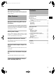
e_ka250.book Page 5 Tuesday, September 5, 2006 4:10 PM Thank you for purchasing this product. (These instructions are for: KA-HD250U.) Before operating this unit, read the instruction manual carefully in order to make sure that the best possible performance is obtained. Main Features Equipped with Analog 26P Camera Connector Connect the Remote Control Unit RM-P210 (sold separately) to control this unit from up to a distance of 100 m away.
e_ka250.book Page 6 Tuesday, September 5, 2006 4:10 PM INTRODUCTION Operating Precautions • In order to ensure that this unit serves you longer, avoid storing or using in the following. Extremely hot or cold places Strong vibrations Dusty places High humidity Near loud noise sources • Do not subject this unit to strong vibration or impact when installing or moving it. • Do not plug in or unplug the camera cable connector when this unit is powered on. • Use only the designated power supplies.
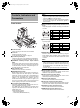
e_ka250.book Page 7 Tuesday, September 5, 2006 4:10 PM MEMO Controls, Indicators and Connectors • When the viewfinder is connected to this terminal, the signal is not output correctly even if the viewfinder is connected to the 3 [VF OUTPUT] terminal. • When connected to the Y/PB/PR terminal of the monitor, the return video signal from the RM-P210 appears in black and white. Front Section 8[TALLY OUTPUT] Tally Signal Output Terminal (D-sub 9 pin) Output tally signals.
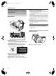
e_ka250.book Page 8 Tuesday, September 5, 2006 4:10 PM INTRODUCTION Controls, Indicators and Connectors (Cont’d) Rear Section g k[CALL] CALL button/Power indicator Lights green when the studio adapter is turned on. Press to send call signal to the remote control unit operator if intercom headset is not in-use. Button indicator changes from green to red when the button is pressed. When this button is pressed and held down, call signal is sent to the remote control unit and the [TALLY] indicator blinks.
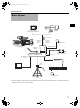
e_ka250.book Page 9 Tuesday, September 5, 2006 4:10 PM PREPARATIONS Basic System View Finder DM-3106 (Astrodesign) V-R70P-HAD (Marshall Electronics) View Finder VF-P400 Conversion plug VF BRIGHT MACRO USER 1 USER 2 USER 3 ND FILTER 2 1 MENU STATUS WHT.
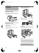
e_ka250.book Page 10 Tuesday, September 5, 2006 4:10 PM PREPARATIONS 2. Release the LOCK RELEASE LEVER. Installation Push the safety lever until the front attachment clip clicks, and then pull the lock lever. Mounting on a Tripod Lock lever Use the screw holes on the bottom to mount on a tripod. There are multiple screw holes. Use well-balanced holes to mount to a tripod. Safety lever 3. Position the camera.
e_ka250.book Page 11 Tuesday, September 5, 2006 4:10 PM Connecting Cables Connecting the Viewfinder (VF-P400) Connect the cables for this device to the camera. 2. 3. 1. 9 4 GENLOCK/AUX IN P TC IN P TC OUT IEEE 1394 REMOTE CH2-AUDIO OUT-CH1 VIDEO HD/SD SDI 1. Loosen the lock lever. Y 1 2 5 Turn the viewfinder lock lever counterclockwise and loosen the lock lever. 6 7 2. Attach the viewfinder. Slide the viewfinder forward along the viewfinder holder guides on the top of this device.
e_ka250.book Page 12 Tuesday, September 5, 2006 4:10 PM PREPARATIONS Connecting to Remote Control Unit RM-P210 3. Connecting a Monitor Prompter video (RM-P210 [AUX VIDEO INPUT] terminal input signal) from RM-P210 can be verified by connecting this unit’s [PROMPTER OUTPUT] terminal located in the front to a monitor using a BNC cable. MEMO Connection Switch off RM-P210 power supply before attempting the connection. 4.
e_ka250.book Page 13 Tuesday, September 5, 2006 4:10 PM MEMO Operation 1. Turn the RM-P210 on. Turn the [POWER] switch of the camera remote control unit to [ON]. CALL button lights up green when the power is turned on. After the [POWER] switch is turned on, camera remote control unit can be operated after about 30 seconds. MEMO After the power is turned on, the camera remote control unit takes about 30 seconds to be ready to communicate with this unit.
e_ka250.book Page 14 Tuesday, September 5, 2006 4:10 PM PREPARATIONS Function Notes on Operating RMP210 GAMMA Some actions are not compatible when setting the GYHD250 with RM-P210 menu operations.
e_ka250.book Page 15 Tuesday, September 5, 2006 4:10 PM OTHERS Specifications RM Multi-pin connector: Composite video signal output (Either Y/PB/PR, RGB or YC separate output signal can be selected) PROMPTER output: PROMPTER video signal output (composite signal) Operating temperature range: • –5°C to 40°C (Humidity below 80%) Allowable storage temperature: • –20°C to 60°C Power supply voltage: DC12 V Power consumption: Max. 40W (GY-HD250, VF-P400) Mass: Approx. 1.8 f Accessories: Instructions ...