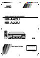
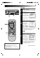
VIDEO CASSETTE RECORDER HR-A42U HR-A22U TV TV/VIDEO TIMER POWER 1 2 3 DISPLAY 4 5 6 ADD 7 8 DAILY 9 WEEKLY ENTER 0 AUX SP/EP T SEARCH Y SKIP SEARCH OSD 2zzREW q REC MENU CANCEL 4PLAY FFzz3 5 STOP 6 PAUSE OK REW 2 POWER CH PLAY FF 3 TV VOL. C.RESET/ CH.
Dear Customer, Thank you for purchasing the JVC VHS video cassette recorder. Before use, please read the safety information and precautions contained in the following pages to ensure safe use of your new VCR. CAUTIONS CAUTION RISK OF ELECTRIC SHOCK DO NOT OPEN CAUTION: TO REDUCE THE RISK OF ELECTRIC SHOCK. DO NOT REMOVE COVER (OR BACK). NO USER-SERVICEABLE PARTS INSIDE. REFER SERVICING TO QUALIFIED SERVICE PERSONNEL.
IMPORTANT PRODUCT SAFETY INSTRUCTIONS Electrical energy can perform many useful functions. But improper use can result in potential electrical shock or fire hazards. This product has been engineered and manufactured to assure your personal safety. In order not to defeat the built-in safeguards, observe the following basic rules for its installation, use and servicing. ATTENTION: 5. Ventilation Slots and openings in the cabinet are provided for ventilation.
USE SERVICING 1. Accessories 1. Servicing To avoid personal injury: • Do not place this product on an unstable cart, stand, tripod, bracket, or table. It may fall, causing serious injury to a child or adult, and serious damage to the product. • Use only with a cart, stand, tripod, bracket, or table recommended by the manufacturer or sold with the product. • Use a mounting accessory recommended by the manufacturer and follow the manufacturer’s instructions for any mounting of the product.
CONTENTS I NSTALLING YOUR NEW VCR 6 Basic Connections .................................. 6 I NITIAL SETTINGS 7 Clock (for HR-A42U) ............................... 7 Automatic Clock Setting ................................... 7 Preparation .......................................................7 Language Select ............................................... 8 Clock Setting .....................................................8 Auto ...............................................................
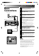
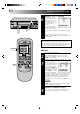
INSTALLING YOUR NEW VCR Basic Connections 1 2 Antenna or Cable Coaxial Cable 3 Flat Feeder Maching Transformer AC Power Cord Back of VCR ANTENNA-IN (Antenna or Cable input) AC Outlet RF Cable (provided) TV 75 ohm terminal RF OUT 4 5 Back of VCR VIDEO CH3 CH4 CHECK CONTENTS Make sure the package contains all of the accessories listed in “SPECIFICATIONS” (Z pg. 34). SITUATE VCR Place the VCR on a stable, horizontal surface.
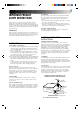
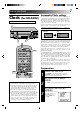
INITIAL SETTINGS Clock Automatic Clock setting (for HR-A42U) OK POWER See page 11 for HR-A22U clock setting procedures. 2 3 The time and date can be set automatically from additional clock setting data that is transmitted by one of the regular TV broadcast channels. We call this TV channel the "Host Channel" and it is a PBS channel in your area. With the antenna cable connected, your VCR can automatically set the clock when the power plug is first connected to an AC outlet.
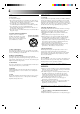
INITIAL SETTINGS (cont.) OK Language Select 2 5/8 6 1 MENU CH q 3 2 1 2 3 4 5 6 7 8 The messages are preset to appear in English. If you want to see them in Spanish or French, place the arrow next to “LANGUAGE SELECT” by pressing CH5∞, then press OK. CUSTOM SET OVERRIDE AUTO CLOCK SET =LANGUAGE SELECT PRESS (5,∞), THEN (OK) PRESS (MENU) TO END SELECT LANGUAGE At the Language Select screen, place the arrow next to the desired language by pressing CH5∞, then press MENU.
OK Semi-Auto 2 5/8 6 MENU CH q 3 2 3 SELECT MODE At the Override Auto Clock Set screen, place the arrow next to “SEMI-AUTO CLOCK SET” by pressing CH▲▼, then press OK. ACCESS SELECT SCREENS At the Semi-Auto Clock Set screen, place the arrow next to the desired mode by pressing CH▲▼, then press OK. SEMI-AUTO CLOCK SET =HOST CHANNEL SELECT TIME ZONE SELECT D.S.T.
INITIAL SETTINGS (cont.) OK 6 2 5/8 6 MENU CH q 3 SELECT D.S.T. MODE You have three choices: D.S.T. SELECT a–Select “AUTO” and the =AUTO adjustment to your VCR’s ON clock will be made OFF according to the incoming signal from the host channel. PRESS (5,∞) TO SELECT PRESS (MENU) TO END b–Select “ON” and the adjustment will be made based on the clock itself. c–Select “OFF” if Daylight Saving Time doesn’t apply to you.
Clock (for HR-A22U) OK POWER See page 7 for HR-A42U clock setting procedures. 2 q 3 5/8 1 2 6 5 ∞ 3 TV/VIDEO CH MENU Preparation TURN ON THE VCR Press POWER. If watching channel 3 or 4, press TV/VIDEO to select the VIDEO mode. VIDEO is displayed on the front display panel. ACCESS ON-SCREEN MENU Press MENU to bring up the Main Menu screen. ACCESS INITIAL SET SCREEN At the Main Menu screen, place the arrow next to “INITIAL SET” by pressing CH5∞, then press OK.
INITIAL SETTINGS (cont.) OK Clock Setting 2 5/8 6 1 MENU NUMBER 1 2 3 4 5 6 7 8 9 Y q 5 SET DATE, TIME AND D.S.T. Press the appropriate CLOCK SET NUMBER keys to set the DATE 1/ 1/96 MON date and time (if only 1 TIME – – : – – AM digit, press "0" first). Press D.S.T. ON CH▲▼ to set AM/PM and D.S.T. (Daylight Saving PRESS NUMBER KEY(0-9) Time) to “ON” (automatic OR (5,∞), THEN (OK) PRESS (MENU) TO END adjustment based on VCR’s clock) or “OFF” (if D.S.T. does not apply to you).
Set Receivable Channels Tuner OK POWER 1 2 5/8 TV/VIDEO MENU POWER 1 2 3 4 5 6 7 2 8 9 5 Y 4 q 5 3 K 2 O T 3 4 Press POWER. If watching on channel 3 or 4, press TV/VIDEO to select the VIDEO mode. VIDEO is displayed on the front display panel. ACCESS MAIN MENU SCREEN Press MENU. ACCESS TUNER SET SCREEN Place the arrow next to "TUNER SET" by pressing CH5∞, then press OK. ACCESS BAND SCREEN Place the arrow next to "BAND" by pressing CH5∞, then press OK.
OK INITIAL SETTINGS (cont.) 2 5/8 6 6 MENU CH q 3 PERFORM AUTO CHANNEL SET Place the arrow next to "AUTO CHANNEL SET" by pressing CH5∞, then press OK. Receivable channels in your area are automatically assigned to the CH5∞ buttons, and non-receivable channels are skipped. AUTO CHANNEL SET CH (TV) 2 ADD SCANNING ... PRESS (MENU) TO END NOTES: ● At the end of Auto Channel Set, “SCAN COMPLETED” appears on screen. ● If the scan was unsuccessful, “SCAN COMPLETED– NO SIGNAL” appears on screen.
OK Add Or Delete A Channel 2 MENU NUMBER 5/8 6 1 CH q 3 2 3 1 2 3 4 5 6 7 8 ADD 0 Y MENU q 5 3 K 4 O 2 Access by performing steps 2 and 3 of the Tuner procedure on page 13. ● To add a channel, go to step 2. ● To delete a channel, skip to step 4. ACCESS AFC SCREEN Place the arrow next to "AFC" by pressing CH5∞, then press OK. MAKE SELECTION Place the arrow next to "SPCL" by pressing CH5∞, then press MENU to return to the Tuner Set screen.
SIMPLE PLAYBACK AND RECORDING Simple Playback 1 3 5/8 6 PL q Make sure the window side is up, the rear label side is facing you and the arrow on the front of the cassette is pointing towards the VCR. Don’t apply too much pressure when inserting. ● The VCR’s power comes on automatically. ● If watching channel 3 or 4, press TV/VIDEO to select the VIDEO mode. VIDEO is displayed on the front display panel. ● The counter is automatically reset to "0H 00M 00S".
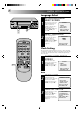
Simple Recording 1 PLAY 2 REC CH NUMBER 1 2 3 4 5 6 7 8 5/8 STOP/EJECT q 3 6 PAUSE 2 3 4 5 6 LOAD A CASSETTE Make sure the record safety tab is intact. If not, cover the hole with adhesive tape before inserting the cassette. SELECT RECORDING CHANNEL Press CH5∞. Or press the appropriate NUMBER keys, then press ENTER. (The channel changes after a few seconds whether you press ENTER or not.) SET TAPE SPEED Press SP/EP to set the recording speed.
PLAYBACK AND RECORDING FEATURES Still Picture Playback FF REW 1 2 5/8 6 2 4 5 6 8 9 0 SE 7 2 4 q 5 3 1 Y T 3 FF REW 6 FRAME-BY-FRAME PLAYBACK Advance the tape one frame by pressing PAUSE again. ● To control the direction of Frame-by-Frame playback, press SEARCH<< or >> during still picture mode. Press PLAY during still picture mode. Slow, Reverse, Reverse Slow Or Fast-Motion Picture Y 3 CH T 2 Press PAUSE.
Manual Tracking Once playback begins, the VCR’s automatic tracking function is engaged. If noise appears in the picture, you can override this and make the adjustment manually. 2 CH q 3 5/8 6 1 2 1 2 3 4 5 6 7 8 3 During playback, press the CH5∞ buttons on the VCR's front panel simultaneously to cancel the automatic tracking mode and enable manual tracking adjust. ADJUST MANUAL TRACKING Press CH5∞ on the VCR's front panel or remote.
PLAYBACK AND RECORDING FEATURES (cont.) Superimpose OK This function, switchable between ON and OFF, determines whether or not operational indicators will appear on screen. 2 5/8 1 6 MENU CH q 3 7 8 2 9 OSD 0 Y 4 q 5 3 K 2 O T 3 6 MENU CH ACCESS MAIN MENU SCREEN Press MENU. ACCESS FUNCTION SET SCREEN Place the arrow next to "FUNCTION SET" by pressing CH5∞, then press OK. ACCESS SUPERIMPOSE SCREEN Place the arrow next to "SUPERIMPOSE" by pressing CH5∞, then press OK.
FF Skip Search AY PL 2 3 REW 5/8 6 1 Press SKIP SEARCH 1 to 4 times during playback. Each press initiates a 30-second period of fast- motion playback. Normal playback resumes automatically. NOTE: To return to normal playback during a Skip Search, press PLAY. STOP q SKIP OVER UNWANTED SECTIONS Repeat Playback VIDEO PLAY SP H M S 1 2 START REPEAT Press and hold PLAY (until "PLAY" blinks on the front display panel) during playback, then release. •The entire tape is played back 20 times.
PLAYBACK AND RECORDING FEATURES (cont.) FF REW POWER Counter Reset 2 5/8 6 PLAY q 3 TIMER 2 3 4 5 6 8 By pressing the DISPLAY button, you can change the display to show the counter reading, channel number or clock time. (Channel number is not displayed during playback.) DISPLAY The Tape position indicator appears on screen when, from the stop mode, you press FF, REW or perform an Index Search.
Record One Program While Watching Another Recording 1 2 q 3 5/8 6 TV/VIDEO 2 During recording... ● If using the RF connection (Z pg. 6), press TV/VIDEO. The VCR's VIDEO indicator goes out and the TV broadcast being recorded disappears. ● If using the AV connection (Z pg. 6), change the TV's input mode from AV to TV. SELECT CHANNEL FOR VIEWING Use the TV’s channel selector to set the channel you want to watch.
TIMER RECORDING Instant Timer Recording (ITR) 2 5/8 6 3 Press REC. ENGAGE ITR MODE Press REC again. ITR blinks and 0:30 appears on the front display panel. SET RECORDING DURATION If you want to record for more than 30 minutes, press REC to extend the time. Each press extends recording time by 30 minutes. ● You can only perform ITR using the REC button on the VCR's front panel. ● After you set the time, the previous display reappears.
OK 25 2 5/8 4 Press the appropriate NUMBER keys or CH5∞ to select a vacant program number, then press OK. The first time you do this, all numbers will be vacant, so just press OK when the screen appears. SET PROGRAM INFORMATION Press the appropriate NUMBER keys to set the date, start/stop time and channel number. Press CH5∞ to set AM/PM and tape speed. Then press OK after AM/PM, channel number and tape speed settings. The next setting that can be set begins flashing.
TIMER RECORDING (cont.) OK POWER Check And Cancel Programs 2 5/8 M TI POWER 1 2 3 4 5 6 7 8 1 6 2 ER MENU CH q 3 3 0 MENU CANCEL 4 Y q 5 3 K 4 O 2 Press TIMER, then press POWER. ACCESS PROGRAM SET SCREEN Press MENU, then press OK. CHECK PROGRAM INFORMATION Press CH5∞ to check the programs in succession. To Cancel A Program . . . 9 T DISENGAGE TIMER 6 CH 5 6 CANCEL A PROGRAM Press CANCEL. ● Repeat steps 3 and 4 as many times as necessary.
Auto Timer OK When activated, this function automatically engages the timer when the VCR's power is turned off, and disengages it when the power is turned on. 2 q CH 2 3 4 5 6 7 8 5/8 6 1 2 TIMER MENU 1 3 3 ACCESS MAIN MENU SCREEN Press MENU. ACCESS FUNCTION SET SCREEN Place the arrow next to "FUNCTION SET" by pressing CH5∞, then press OK. ACCESS AUTO TIMER SCREEN Place the arrow next to "AUTO TIMER" by pressing CH5∞, then press OK. Now skip to step 2 of the procedure below.
EDITING You can use your VCR as the player or the recorder. Edit To Or From Another 1 VCR Player Your VCR AUDIO OUT VIDEO OUT AUDIO IN VIDEO IN Another VCR Recorder 1 2 3 4 5 6 7 8 9 0 NUMBER "0" Y T 2 4 q 5 3 6 2 3 4 5 MAKE CONNECTIONS Connect an AV cable (not supplied) between the player’s VIDEO OUT and AUDIO OUT connectors and the recorder’s VIDEO IN and AUDIO IN connectors.
You can use a camcorder as the player and your VCR as the recorder. Edit From A Camcorder Recorder 1 Your VCR 2 q VIDEO IN AUDIO IN VIDEO OUT Camcorder AUDIO OUT Player 1 2 3 4 5 6 7 8 9 0 NUMBER "0" Y T 2 4 q 5 3 6 3 5/8 2 6 3 4 5 MAKE CONNECTIONS Connect an AV cable (not supplied) between the camcorder’s VIDEO OUT and AUDIO OUT connectors and your VCR’s VIDEO IN and AUDIO IN connectors.
SPECIAL FEATURES Multi-Brand Remote Control TV/VIDEO In addition to controlling several functions on JVC remote control TVs, the VCR's remote control can control these functions on the TV brands listed below. If your television is a JVC, you don’t have to set the code in step 1. POWER TV 1 2 3 4 5 6 8 ADD 9 PLAY 7 1 Y 2 4 q 5 ST O P T 0 3 FF REW 6 PAUSE REC MENU VOL. +/- CH OK CANCEL 2 SELECT TV BRAND Refer to the chart below.
TROUBLESHOOTING Before requesting service for a problem, use this chart and see if you can repair the trouble yourself. Small problems are often easily corrected, and this can save you the trouble of sending your VCR off for repair. POWER SYMPTOM POSSIBLE CAUSE CORRECTIVE ACTION 1. The power won’t come on. ● The power cord is disconnected. Connect the power cord. 2. The clock works, but the VCR’s power won’t come on. ● The TIMER mode is engaged with Auto Timer set to "OFF" (Z pg. 27).
TROUBLESHOOTING (cont.) TIMER RECORDING SYMPTOM 1. Timer recording won’t work. POSSIBLE CAUSE ● The clock and/or the timer have been set incorrectly. ● The timer is not engaged. ● The VCR has not been set up properly. CORRECTIVE ACTION Check or re-perform the clock/timer settings to ensure correctness. Press TIMER and check to make sure that TIMER appears on the front display panel. Re-perform the set-up procedures. 2. On-screen timer programming won’t work. ● Timer recording is in progress.
QUESTIONS AND ANSWERS PLAYBACK RECORDING Q. What happens if the end of the tape is reached during playback or search? A. The tape is automatically rewound to the beginning. Q. When I pause and then resume a recording, the end of the recording before the pause is overlapped by the new recording. Why does this happen? A. This is normal. It reduces distortion at the pause and resume points. ○ ○ ○ ○ ○ ○ ○ ○ ○ ○ ○ ○ ○ ○ ○ ○ ○ ○ ○ ○ ○ ○ ○ ○ ○ ○ ○ ○ Q.
GENERAL Power requirement Power consumption Temperature Operating Storage Operating position Dimensions (W x H x D) SPECIFICATIONS : AC 120 V` , 60 Hz : 19 W : 5°C to 40°C (41°F to 104°F) : –20°C to 60°C (–4°F to140°F) : Horizontal only : 360 x 94 x 276 mm (14-3/16" x 3-3/4" x 10-7/8") : 3.4 kg (7.5 lbs) : VHS NTSC standard Weight Format Maximum recording time SP : 210 min. with ST-210 video cassette EP : 630 min.
INDEX List Of Terms This guide serves as a quick way to locate frequently used terms and on-screen display names. The first page on which the term appears is listed. Most terms appear more than once in the instruction manual. A M Add Channel ...............................................................15 AFC ............................................................................. 15 Auto Channel Setting ..................................................14 Auto Clock ..........................
INDEX (cont.) FRONT VIEW 1 3 2 4 REW 2 POWER 5 FF 3 PLAY OK VIDEO 6 AUDIO 7 MENU 8 1 Power ON/OFF Button (Z pg. 7 or 11) 2 Cassette Loading Slot 3 Rewind Button (Z pg. 16) Reverse Search Button (Z pg. 18) 4 Play Button (Z pg. 16) 5 Fast-Forward Button (Z pg. 16) Forward Search Button (Z pg. 18) 6 Video Input Connector (Z pg. 29) 7 Audio Input Connector (Z pg.
FRONT DISPLAY PANEL 1 2 3 ITR TIMER VIDEO SPAM EPPM 8 4 5 H 90 M ! 1 Video Mode Indicator (Z pg. 7 or 11) 2 Instant Timer Recording Indicator (Z pg. 24) 3 Timer Mode Indicator (Z pg. 25) 4 Clock Display (Z pg. 7) 5 Counter Display (Z pg. 22) 6 Recording Mode Indicator (Z pg. 17) 7 Play Mode Indicator (Z pg. 16) 6 S 7 REC PLAY PAUSE @ 8 “Cassette Loaded” Mark 9 Tape Speed Indicators (Z pg. 17) 0 AM/PM Indicators (Z pg. 7) ! Channel Display [“AU” for AUX mode] (Z pg.
FOR SERVICING HOW TO LOCATE YOUR JVC SERVICE CENTER TOLL FREE: 1-800-252-5722 Dear customer: In order to receive the most satisfaction from your purchase, read the instruction booklet before operating the unit. In the event that repair is necessary, or for the address nearest your location, please refer to the factory service center list below or within the Continental United States, call 1-800-252-5722 for your authorized servicer. Remember to retain your Bill of Sale for Warranty Service.
WARRANTY LIMITED WARRANTY CONSUMER VIDEO 1-90 JVC COMPANY OF AMERICA warrants this product and all parts thereof, except as set forth below ONLY TO THE ORIGINAL PURCHASER AT RETAIL to be FREE FROM DEFECTIVE MATERIALS AND WORKMANSHIP from the date of original retail purchase for the period as shown below. ("The Warranty Period") PARTS 1 YR LABOR 90 DAYS THIS LIMITED WARRANTY IS VALID ONLY IN THE FIFTY (50) UNITED STATES, THE DISTRICT OF COLUMBIA AND IN COMMONWEALTH OF PUERTO RICO.
HR-A42/A22U JVC COMPANY OF AMERICA DIVISION OF US JVC CORP. 41 Slater Drive, Elmwood Park, N.J. 07407 COPYRIGHT © 1996 VICTOR COMPANY OF JAPAN, LTD.