VIDEO CASSETTE RECORDER CONTENTS SAFETY FIRST HR-A630EK HR-A631EK 2 Safety Precautions .................................... 2 Some Do’s And Dont’s ............................. 3 INSTALLING YOUR NEW RECORDER 4 Basic Connections ................................... 4 Tune The TV To Your Video Recorder ...... 5 Connection To A Satellite Receiver .......... 6 Connection To A Stereo System ............... 7 INITIAL SETTINGS 8 Tuner Set .................................................. 8 Clock Set ....
SAFETY FIRST Safety Precautions The rating plate and the safety caution are on the rear of the unit. WARNING: DANGEROUS VOLTAGE INSIDE WARNING: TO PREVENT FIRE OR SHOCK HAZARD, DO NOT EXPOSE THIS UNIT TO RAIN OR MOISTURE. IMPORTANT IMPORTANT Connection to the mains supply in the United Kingdom. DO NOT cut off the mains plug from this equipment.
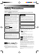
4-STEP QUICK SET UP 1 2 BASIC CONNECTION PAGE 4 3 TUNE THE TV TO YOUR VIDEO RECORDER PAGE 5 TUNER SET PAGE 8 4 CLOCK SET PAGE 9 Some Do's And Don'ts On The Safe Use Of Equipment This equipment has been designed and manufactured to meet international safety standards but, like any electrical equipment, care must be taken if you are to obtain the best results and safety is to be assured. DO read the operating instructions before you attempt to use the equipment.
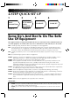
INSTALLING YOUR NEW RECORDER Basic Connections Back of TV RF Cable (provided) 21-pin SCART Cable Aerial terminal 21-pin SCART connector Mains Power Cord It's essential that your video recorder be properly connected. Follow these steps carefully. THESE STEPS MUST BE COMPLETED BEFORE ANY VIDEO OPERATION CAN BE PERFORMED. 1 2 3 CHECK CONTENTS Make sure the package contains all of the accessories listed in “Specifications” (Z pg. 43).
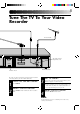
Tune The TV To Your Video Recorder TV Aerial Cable R L RF output channel adjustment screw ANT. IN AUDIO OUT AV2 IN 32 40 RF OUT ON–TEST–OFF AV1 IN/OUT RF OUT RF OUT switch Back of Recorder The video recorder sends picture and sound signals via the RF connecting cable to your TV on UHF channel 36. 1 2 TURN ON THE RECORDER Press OPERATE. 3 SELECT OUTPUT MODE Set the RF OUT switch on the back of the recorder to TEST. 4 SET TV PRESET Set your TV to the video preset (UHF channel 36).
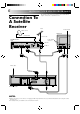
INSTALLING YOUR NEW RECORDER (cont'd) Connection To A Satellite Receiver The AV2 IN socket on the rear panel of your recorder allows simple connection to a satellite receiver. Aerial Aerial terminal Outdoor Unit Back of TV Satellite Cable TV Aerial cable 21-pin SCART connectors Satellite Receiver Unit ANT. IN DECODER VCR TV RF OUT EXT.2 EXT.1 Mains outlet R L AUDIO OUT AV2 IN ANT.
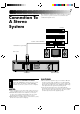
Connection To A Stereo System These instructions enable you to connect your video recorder to your Hi-Fi stereo system (if you have one) and listen to the soundtrack through the stereo. FM Tuner CD Player Stereo Amplifier AUX IN or TAPE MONITOR I I I I I I I I I I I I I I I I I I I I I I I I I I I I I I I I I I I I I I I I I I I Audio Cable (not provided) Mains outlet Speaker R L AUDIO OUT AV2 IN Television Speaker ANT.
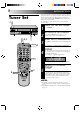
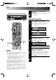
INITIAL SETTINGS 1 The following procedure describes how to select automatic channel setting. OPERATE Tuner Set Your recorder needs to memorise all necessary stations in preset positions in order to record TV programmes. ATS+ (Auto Tuning System) automatically assigns all receivable stations in your area to call them up with the TV PROG. buttons without going through any vacant channels. 6 TV PROG.
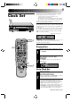
If you performed Auto Channel Set (Z pg. 8), the recorder’s built-in clock is also set automatically. The Auto and Manual clock setting procedures are necessary when . . . – a power outage of more than 3 minutes occurs. – the tuner has been set manually. – the user desires to set the clock slightly ahead of the actual time. – the clock was not set even after Auto Tuner Set was performed. Whether you perform Auto or Manual clock setting, you can use the convenient Just Clock function.
INITIAL SETTINGS (cont.) 4 q RETURN TO NORMAL DISPLAY Once clock setting is completed, press CLOCK to return to the normal display. 6 Manual Clock Set 3 2 2 3 4 5 6 7 8 9 CL 6 O CK 1 SET DATE AND TIME Press PUSH JOG%fi to set the hour, then press OK. The “minutes” display begins blinking. Repeat the procedure to set the minutes, day, month and year. Hour ≠ Minutes ≠ Day Month ≠ ≠ 0 D Year ≠ M After inputting the year, press OK and the Just Clock display appears.
PLAYBACK The easiest, most basic operation possible with your video recorder is tape playback. Already-recorded signals on a video tape are read by your video recorder and displayed on your TV just like a TV programme. Basic Playback 2 PL AY 1 q 6 W STOP/EJECT RE 2 2 1 2 3 4 5 6 7 8 9 4 Make sure the window side is up, the rear label side is facing you and the arrow on the front of the cassette is point toward the recorder. Don’t apply too much pressure when inserting.
PLAYBACK (cont.) Take advantage of special functions possible with the recorder’s controls or the remote control. Playback Features Still Picture/Frame-By-Frame Playback FF 1 PL AY REW 4 5 6 7 8 9 ACTIVATE FRAME-BY-FRAME PLAYBACK Press PAUSE again. To resume normal playback, press PLAY. Slow Motion ACTIVATE SLOW-MOTION PLAYBACK During still picture, press and hold PAUSE for 2 seconds, then release. Press and release again to return to still picture.
Manual Tracking Your video recorder is equipped with automatic tracking control. During playback, you can override this and adjust the tracking manually by pressing the TV PROG. buttons. TV PROG. q REVIEW 2 1 2 3 4 5 6 7 8 9 0 TV PROG. 6 OVERRIDE AUTOMATIC TRACKING 1 Press SP/LP ( tracking. 2 Press TV PROG. + or – to adjust tracking. 3 ) on the remote to engage manual ADJUST TRACKING MANUALLY RETURN TO AUTOMATIC TRACKING Press SP/LP ( matic tracking.
PLAYBACK (cont.) FF Index Search PL AY Your recorder automatically marks index codes at the beginning of each recording. This function gives you quick access to any one of 9 index codes in either direction. NOTE: Before starting, make sure the recorder is in the Stop mode. REW O ST Press PUSH JOG or (™ or £). “–1” or “+1” is displayed on the display panel and search begins in the corresponding direction.
NTSC Playback PLAY Your video recorder is equipped with NTSC circuitry that can play back NTSC tapes. q 2 1 2 3 4 5 6 7 8 9 0 6 1 2 LOAD A CASSETTE Insert a cassette recorded in NTSC. START PLAYBACK Press PLAY. “NT” appears on the display panel. ● Some TVs shrink the picture vertically and place black bars at the top and bottom of the screen. This is not a malfunction on the part of either the video recorder or the TV. ● The picture may roll up and down.
PLAYBACK (cont.) The remote control is capable of controlling two JVC video recorders independently; one set to respond to the remote control’s A code control signals and another set to respond to B code control signals. The remote control is preset to send A code signals because your video recorder is initially set to respond to A code signals. You can easily modify your video recorder to respond to B code signals.
RECORDING TV signals being received by the recorder’s built-in tuner can be recorded onto a video tape. You can “capture” a TV programme using your video recorder. PLAY Basic Recording 4 1 5 RE CO RD PAUSE 6 STOP/EJECT 3 TV PROG. SP /L P q 2 65 2 2 NUMBER 1 2 3 4 5 6 7 8 9 0 TV PROG. 3 PLAY 4,5 PAUSE RECORD 3 4 5 6 Insert a cassette with the record safety tab intact. ● The counter is reset to 0:00:00 and the recorder power comes on automatically.
RECORDING (cont.) Record One Programme While Watching Another Recording Features 1 TV PROG. q 2 3 4 5 6 7 8 9 TV PROG. 3 1 ● The programme selected with the TV’s preset controls appears on the TV screen while the one selected with the TV PROG. button is recorded on the tape. To Record NICAM Stereo And Bilingual Programmes Your recorder is equipped with a digital stereo sound decoder for reception of NICAM stereo and bilingual broadcasts.
Elapsed Recording Time Indication You can check the exact time of a recording. RECORD q DISPLAY 2 1 2 3 4 5 6 7 8 9 6 1 2 Press DISPLAY so that a counter reading appears on the dispay panel. ● If you press DISPLAY again, clock display appears. RESET COUNTER Press C. RESET before starting recording or playback. ● The counter is reset to “0:00:00” and shows the exact elapsed time as the tape runs.
TIMER RECORDING With Video Plus+, timer programming is greatly simplified because each TV programme has a corresponding code number which your recorder is able to recognize. Information On Video Plus+ “Guide Channel” refers to the assigned TV station numbers, according to broadcast area, for Video Plus+ timer recording. IMPORTANT Perform the following procedure after the channel setting steps on pages 8 and 29 – 31, and after the Clock Set procedure on page 9.
4 5 4 ENTER PLUSCODE NUMBER Press OK, and "– –" appears. Then, using the NUMBER keys, input the PlusCode (found in most TV listings) of a program scheduled to be broadcast on each station on the list from step 1, starting at the top. If you enter the wrong number, press CANCEL and input the correct number.
TIMER RECORDING(cont.) Before performing the following steps, insert a cassette with the safety tab in place. The recorder power will come on automatically. Video Plus+ Timer Recording 1 Before performing Video Plus+ Timer Recording, be sure to read "Information on Video Plus+" on page 20. q 2 ACCESS TIMER PROGRAMMING DISPLAY Press PROG. ENTER PLUSCODE NUMBER Press the NUMBER keys to enter the PlusCode number of a programme you wish to record.
6 TIMER 4 q ADD TIME 6 C D :P CANCEL 4 SP/LP Press SP/LP ( ) to set the tape speed. RETURN TO NORMAL DISPLAY Press OK. ● Repeat steps 1 – 5 for each additional programme. ENGAGE RECORDER’S TIMER MODE Press TIMER. NOTE: 2 3 5 SP/LP 4 6 SET TAPE SPEED 1 2 4 5 3 ILY DA 6 7 8 9 WEEKLY TIMER 0 6 For safety, your recorder disables all other functions while in the Timer mode.
TIMER RECORDING(cont.) Regular Timer Programming Remember, the clock must be set before you can progamme the timer (Z pg. 9). Before performing the following steps, insert a cassette with the safety tab in place. The recorder power will come on automatically. 1 2 q ACCESS TIMER PROGRAMMING DISPLAY Press PROG. ACCESS PROGRAMME DISPLAY Press START +/–. SP 6 ● If you're not receiving PDC (Programme Delivery Control), press NUMBER key "7" to set to "OFF" so that the indicator disappears (Z pg. 26).
TIMER 25 6 ENTER PRESET POSITION Press TV PROG. +/–. Day Month ≠ ≠ Preset position ≠ SP D q 4 5 7 6 9 8 WEEKLY 9 TV PROG. 6 TIMER 0 7 3 AI 2 D 1 8 LY 2 7 SP/LP 7 SP/LP 3 1 OK M 6 8 9 SET TAPE SPEED Press SP/LP ( ) to set the tape speed. RETURN TO NORMAL DISPLAY After confirming all information is correct, press OK and the normal display appears. ● Repeat steps 1–8 for each additional programme. ENGAGE RECORDER’S TIMER MODE Press TIMER.
TIMER RECORDING(cont.) Check And Cancel Programmes q 6 1 ACCESS PROGRAMME DISPLAY Press PROG CHECK. The recording start and stop times appear on the front display panel. Then press OK and the date and the preset position appear. Each time you press PROG CHECK the next program’s information appears. If All Information Is Correct . . . . . . programming is completed. If You Wish To Revise Data . . . . . . with the recorder's power turned on, go to step 2. If You Wish To Cancel A Program . . . . . .
EDITING You can use your video recorder as the source player or the recording deck. Edit To Or From Another 1 Video Recorder . 2 2 1 2 3 4 5 6 7 8 9 0 NUMBER "0" TV PROG. 3 4 MAKE CONNECTIONS Connect the player’s AUDIO/VIDEO OUT connector to the recorder’s AUDIO/VIDEO IN connector. When Using Your Video Recorder As The Source Player . . . . . . connect its AV1 IN/OUT connector to the recording deck. When Using Your Video Recorder As The Recording Deck . . . . . .
EDITING (cont.) Edit From A Camcorder 1 2 2 1 2 3 4 5 6 7 8 9 0 NUMBER "0" You can use a camcorder as the source player and your video recorder as the recorder. TV PROG. 3 4 3 1 Your recorder Recorder Cable adapter VIDEO OUT Camcorder AUDIO OUT Player Audio/Video signals MAKE CONNECTIONS Connect the camcorder’s AUDIO/VIDEO OUT connectors to the recorder’s AUDIO/VIDEO input connectors. SET RECORDER’S INPUT MODE ● If you're using the AV1 IN/OUT connector . . . . . .
USING THE CONFIRMATION DISPLAY Storing Channels Manually Store channels that were not stored during Auto Channel Set. CH SET q STORE 6 1 Press and hold CH SET for more than 2 seconds. "AUTO" appears on the front display panel. 2 Press PUSH JOG%fi to select “MANU”(AL), then press OK. The Confirmation display appears. 3 2 NUMBER 1 2 3 4 5 6 7 8 9 ACCESS CH.
USING THE CONFIRMATION DISPLAY (cont.) Perform steps 1 and 2 on page 29 to access the Confirmation display before continuing. Delete A Channel CH SET q 2 3 4 5 6 7 8 9 1 3 1 Press PUSH JOG% fi until the station you want to delete is displayed. DELETE STATION Press CANCEL. ● The stations following the cancelled station all move up one position. ● Repeat steps 1 and 2 as necessary. RETURN TO NORMAL DISPLAY Press CH SET.
Perform steps 1 and 2 on page 29 to access the Confirmation display before continuing. Set Stations (A) CH SET q 6 1 2 2 1 2 3 4 5 6 7 8 9 3 0 4 SELECT ITEM Press PUSH JOG%fi until the item you want is displayed. Then press OK twice and the station’s name (or "– –") begins blinking. SELECT NEW STATION Press PUSH JOG%fi until the new station’s name you want to store begins blinking. Registered station names (Z pg. 33) appear as you press PUSH JOG%fi . SWITCH STATIONS Press OK.
USING THE CONFIRMATION DISPLAY (cont.) Perform steps 1 and 2 on page 29 to access the Confirmation display before continuing. Fine-Tuning Channels Already Stored q 6 CH SET 1 2 SELECT CHANNEL TO FINE-TUNE Press PUSH JOG% fi until the channel you want to tune is displayed. ACCESS MANUAL CH. SET DISPLAY Press OK three times. The Manual Ch. Set display appears. 2 1 2 3 4 5 6 7 8 9 3 0 3 1 PUSH JOG OK 4 PERFORM TUNING Press PUSH JOG% fi until the picture is its clearest.
TV STATION AND ID LIST STATION NAME ID* STATION NAME ID* Anglia TV ARD ARTE BBC1 BBC2 Berlin 1 Berlin 2 Border TV Bayern1 Bayern3 BRT1 BRT2 Children Ch Canal + CNN Channel TV Central TV Channel 4 Channel 5 DRS DR TV DSF Euronews Euronews Eurosports France1 France2 France3 Granada TV Grampian TV Hessen1 Hessen3 HRT HTV ITV Network Kabelkanal London MDR MTV Nord3 NDR1 NDR3 NED1 NED2 NED3 Network 2 NRK N-TV Offener Kanal ORF1 ORF2 ORF3 OWL 3 Premiere PR07 RAI1 RAI2 RAI3 RB1 RB3 Rikisutvarpid-S RTBF 1 R
TV STATION CHANNEL NUMBER GUIDE Only the main stations are listed. There are in addition many relay stations, and full lists are available from BBC and ITC. BBC1 BBC2 ITV CH4 London & South-East Bluebell Hill ............................. Crystal Palace ........................... Dover ........................................ Heathfield ................................. Oxford ......................................
TROUBLESHOOTING Before requesting service for a problem, use this chart and see if you can repair the trouble yourself. Small problems are often easily corrected, and this can save you the trouble of sending your video recorder off for repair. POWER SYMPTOM POSSIBLE CAUSE CORRECTIVE ACTION 1. No power is applied to the recorder. ● The mains power cord is disconnected. Connect the mains power cord. 2. The clock is functioning properly, but the recorder cannot be powered.
TROUBLESHOOTING (cont.) 3. Tape-to-tape editing is not possible. 4. Camcorder recording is not possible. ● The source (another video recorder, camcorder) has not been properly connected. ● All necessary power switches have not been turned on. ● The input mode is not correct. Confirm that the source is properly connected. ● The camcorder has not been properly connected. ● The input mode is not correct. Confirm that the camcorder is properly connected. Set the input mode to “AU”.
QUESTIONS AND ANSWERS PLAYBACK RECORDING Q. What happens if the end of the tape is reached during playback or search? A. The tape is automatically rewound to the beginning. Q. When I pause and then resume a recording, the end of the recording before the pause is overlapped by the beginning of the continuation of recording. Why does this happen? A. This is normal. It reduces distortion at the pause and resume points.
INDEX List Of Terms This guide serves as a quick way to loacte frequently used terms. The first page on which the term appears is listed. Most terms appear more than once in the instruction manual. A A/B Code Switch ............................................. Z pg. 16 A-Code Signals ................................................ Z pg. 16 Aerial ................................................................ Z pg. 4 Audio Monitor ................................................ Z pg.
FRONT VIEW 1 2 OPERATE 4 5 6 3 TIMER TV PROG SP LP I T R EP D W NORM L R D 7 1 OPERATE Button turns recorder on/off (loading a cassette also turns power on). Z pg. 5 2 TIMER Button engages timer standby mode. Z pg. 23 3 Cassette Loading Slot is where cassette is inserted; door closes, "cassette loaded" indicator lights up on front display panel. 4 Rewind [REW] Button rewinds tape; initiates high-speed reverse search. Z pg.
INDEX (cont.) REMOTE CONTROL % ^ CH SET A B OPERATE STORE CLOCK DISPLAY 2 1 2 3 ADD TIME 4 5 6 DAILY WEEKLY 7 8 9 C.RESET AUX CANCEL 0 START STOP TIMER TV PROG. DATE EXPRESS PROGRAMMING AUDIO MONITOR TV/VIDEO TV VCR (MONITOR) PROG C HECK 1 G PRO TV VOL. PUSH JOG 3 OK ) q w e r t y u i o p Q W E R Buttons shown in white ( ) can also be used to operate JVC TVs (Z pg. 41). % 1 CH SET Button accesses Ch. Set display; closes Confirmation display. Z pg.
Installing Batteries 1 Open the battery compartment cover. 2 Insert 2 "R6"-size batteries (provided) in the correct directions. 3 Replace the cover. How To Use The remote control can operate most of your video recorder's functions, as well as basic functions of JVC TV sets. See below. ● Point the remote control toward the sensor window. ● The maximum operating distance of the remote control is about 8 m.
INDEX (cont.) REAR VIEW 2 1 5 4 3 L R AUDIO OUT ANT. IN AV2 IN 32 40 RF OUT ON–TEST–OFF AV1 IN/OUT RF OUT 6 7 1 Mains Power Cord supplies power to recorder. Z pg. 4 2 AUDIO OUT (L/R) Connectors enable connection of audio cassette recorder, TV or second video recorder for dubbing. Z pg. 7 3 AV1 IN/OUT SCART Connector enables AV connection to TV or second recorder; input recordable when "AU 1" selected. Z pg.
SPECIFICATIONS GENERAL Power requirement : Power consumption : Temperature Operating : Storage : Operating position : Dimensions (WxHxD) : Weight : Format : Maximum recording time (SP) : (LP) VIDEO/AUDIO Signal system Recording system Signal-to-noise ratio Horizontal resolution Frequency range Input/Output AC 220 – 240 V`, 50/60 Hz 24 W 5°C to 40°C –20°C to 60°C Horizontal only 400 x 94 x 338 mm 4.3 kg VHS PAL standard 240 min. with E-240 video cassette : 480 min.
HR-A630EK/A631EK VICTOR COMPANY OF JAPAN, LIMITED COPYRIGHT © 1996 VICTOR COMPANY OF JAPAN, LTD.